Based on a number of enquiries received this week, we thought it would be useful to clarify and streamline the Hamilton By Design philosophy regarding engineering-grade reality capture, drafting and engineering outcomes.
Not all scans are equal.
Not all point clouds are equal.
Not all meshes are equal.
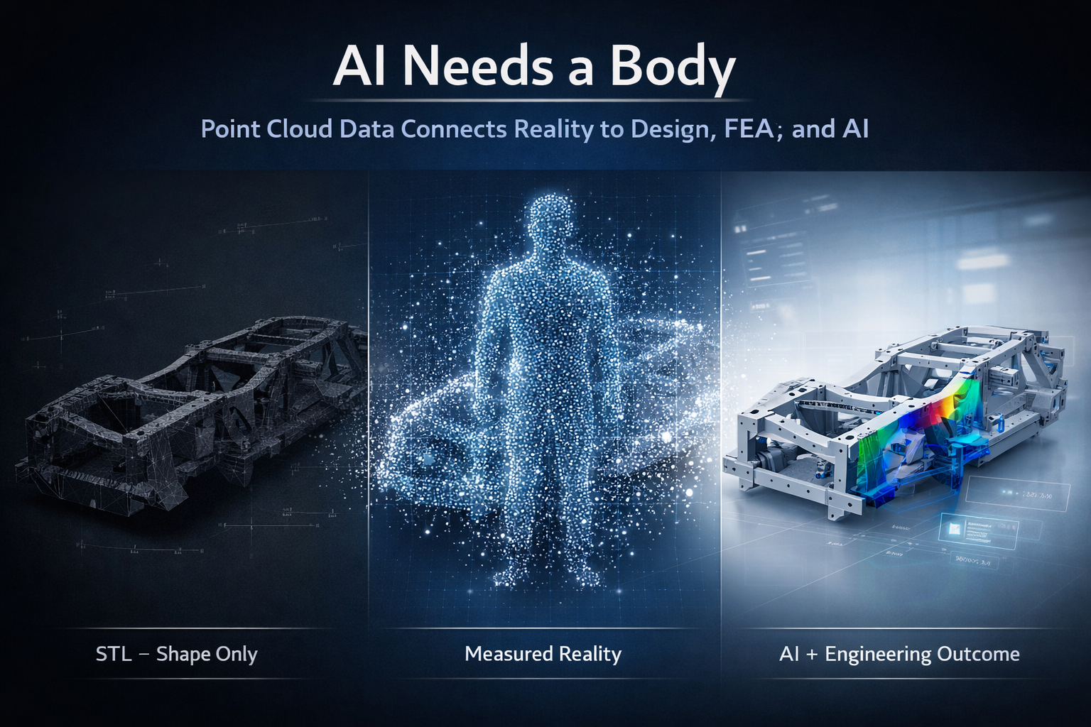
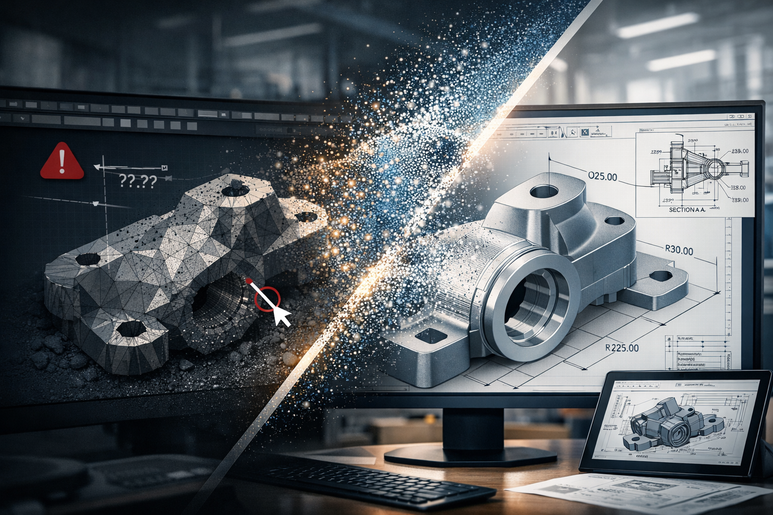
One of the biggest misconceptions in industry is that once a point cloud has been generated, or once a mesh file or STL model has been created, the engineering work is complete. In reality, capturing a scan is only the beginning of the process.
The value does not come from simply obtaining a file.
The value comes from understanding the required outcome and ensuring the data collected is appropriate for that purpose.
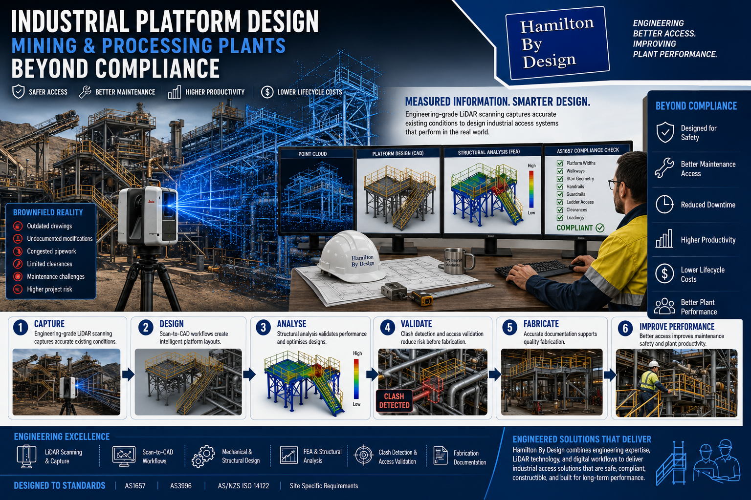
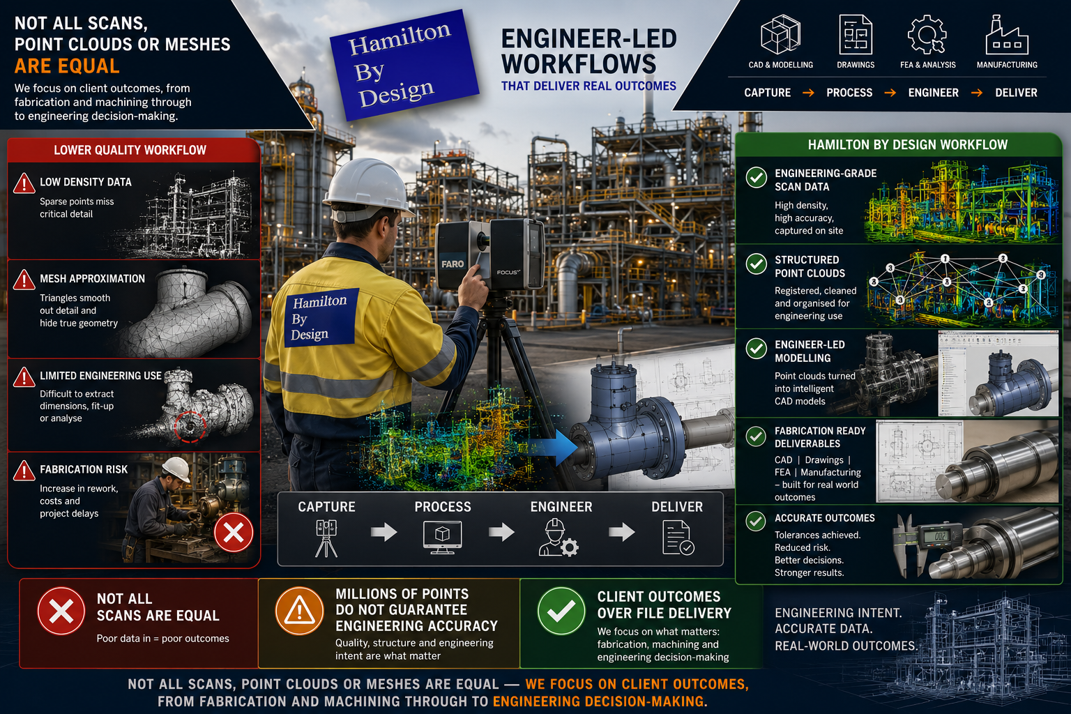
At Hamilton By Design, we are engineer-led and provide engineering-grade scanning and reality capture services designed around the intended engineering outcome.
Whether you require outcomes associated with:
- Fabrication and steel fit-up
- Mechanical drafting
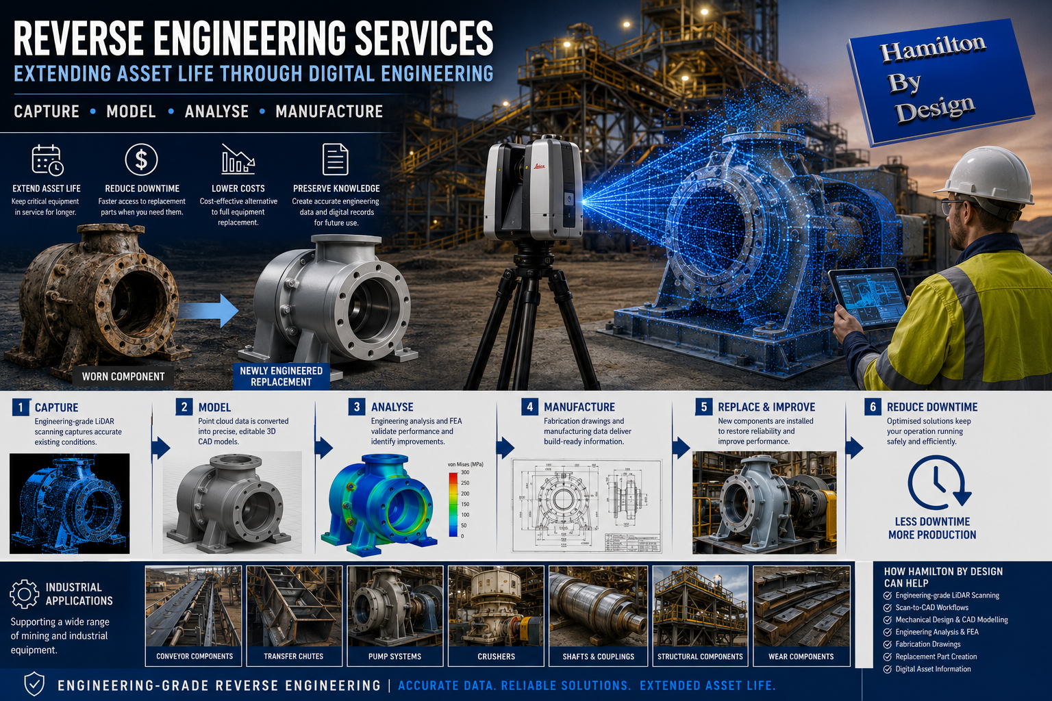
- Reverse engineering
- Plant modifications
- Mechanical assemblies
- Precision machining
- Toolmaking
- Engineering studies and analysis
our process begins by understanding the final requirement rather than assuming one scan methodology can satisfy every project.
Because different engineering outcomes require different levels of information.
A Scan Is Not the Final Product
Many discussions begin with questions such as:
“Can you provide a point cloud?”
“Can you create a mesh?”
“Can you provide an STL file?”
These are important questions; however, they often miss the larger engineering discussion.
The better question is:
What are you trying to achieve?
The same scan dataset may be used for several completely different purposes:
- General plant layouts
- Fabrication fit-up
- Reverse engineering
- Structural modifications
- Mechanical assemblies
- Existing condition verification
- Bearing and shaft measurements
- Precision tooling
The level of detail required for these outcomes can vary significantly.
A dataset that may be suitable for one application may be completely unsuitable for another.
Drafting Is More Than Drawing Lines
Modern industrial drafting has evolved considerably.
A capable draftsperson or designer should understand:
- Point cloud datasets
- Mesh and STL files
- Scan quality and limitations
- Measurable geometry development
- CAD model generation
- Manufacturing requirements
- Installation requirements
- Practical engineering considerations
The objective is not simply creating a drawing.
The objective is converting real-world conditions into useful engineering information.
Drafting Should Understand Manufacturing Reality
At Hamilton By Design we believe drafting extends beyond geometry displayed on a screen.
Strong design outcomes often come from understanding how components are actually manufactured, assembled and maintained.
Experience or understanding in areas such as:
- Fabrication
- Machining
- Toolmaking
- Manufacturing processes
- Site installation
- Plant maintenance
can significantly improve engineering decisions.
Understanding manufacturing realities affects:
- Material selection
- Weld access
- Machining stock allowances
- Tolerances
- Assembly methods
- Maintenance requirements
- Manufacturing costs
A component may appear correct in CAD while still creating practical manufacturing issues.
Questions still need to be asked:
- Can the component actually be manufactured?
- Can welding equipment physically access the location?
- Is sufficient machining stock available?
- Can bearings be assembled correctly?
- Can maintenance personnel access components?
Good drafting is not simply producing drawings.
Good drafting understands the complete journey from concept through to manufacture and operation.
Data Quality In = Data Quality Out
At Hamilton By Design we regularly work with:
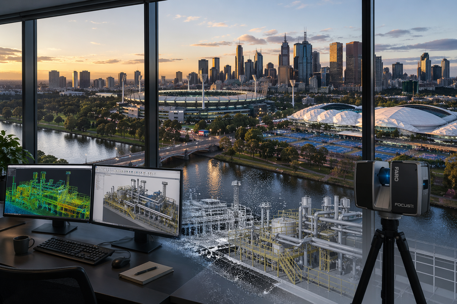
- Engineering-grade point clouds
- Surface meshes
- STL datasets
- Reverse engineered components
- Existing CAD models
One engineering principle remains consistent:
You cannot create information that was never captured.
Software may improve visual appearance and optimise workflows; however, software cannot accurately create missing information.
Examples include:
- Higher point density generally captures more geometric detail
- Lower point density captures less information
- Reduced mesh resolution removes geometric definition
- STL files can contain smoothing effects
- Mesh reduction can remove critical engineering features
Reducing points reduces available information.
At some point, a measured representation becomes an approximation.
Bigger Data Sets Are Not Always Better
Many people assume larger datasets automatically create better outcomes.
The reality is there is a balance between detail and practicality.
Large datasets may increase:
- Processing time
- Storage requirements
- Hardware demands
- Registration effort
- Modelling time
- File management complexity
- Project delivery time
The objective should not be creating the largest point cloud possible.
The objective should be collecting sufficient information to satisfy the engineering requirement.
Greater Accuracy Usually Comes With Greater Cost
Higher accuracy requirements typically require greater effort.
As required accuracy increases, additional work may include:
- Increased point density
- Larger point cloud datasets
- Higher mesh resolution
- Additional scan positions
- Greater registration effort
- Increased verification requirements
- Additional modelling effort
- More engineering review
As detail increases:
- File sizes increase
- Processing requirements increase
- Engineering effort increases
- Costs may increase
The objective should not be maximum data.
The objective should be the correct data.
One Project Can Contain Multiple Tolerances
One of the most common misunderstandings is assuming an entire project operates under one tolerance requirement.
Real engineering projects rarely operate this way.
Consider a pulley assembly.
The fabricated support structure, guards and mounting arrangement may comfortably operate within fabrication tolerances of:
Approximately ±2 mm
However, the same assembly may also include:
- Shaft diameters
- Bearing journals
- Keyways
- Bearing fits
- Machined interfaces
These features may require significantly tighter dimensional control.
Typical examples include:
Fabrication and steel fit-up
Approximately ±2 mm
Machined components and mechanical interfaces
Approximately ±0.1 mm
Precision tooling and specialised manufacturing
Potentially <0.1 mm
A fabricator and a toolmaker are not working to the same expectations.
Applying toolmaking tolerances to general fabrication may unnecessarily increase complexity and cost.
Likewise, applying fabrication assumptions to precision-machined components may create significant issues.
One mesh does not automatically solve every engineering requirement.
The Hamilton By Design Approach
At Hamilton By Design we work backwards from the final outcome.
Questions we commonly ask include:
- Is the project for fabrication?
- Is machining required?
- Is reverse engineering required?
- Is there a critical bearing or shaft interface?
- Is this for plant modifications?
- Is this for a precision component?
- Is this for engineering studies?
These answers determine:
- Scan methodology
- Point cloud density
- Registration strategy
- Modelling approach
- Verification requirements
- Engineering effort
- Final deliverables
We focus on providing the right information at the right level for the intended purpose.
Because engineering-grade scanning is not about creating the biggest point cloud.
Engineering-grade scanning is not about creating the largest mesh.
Engineering-grade scanning is about producing reliable information that supports real-world engineering outcomes.

Our clients