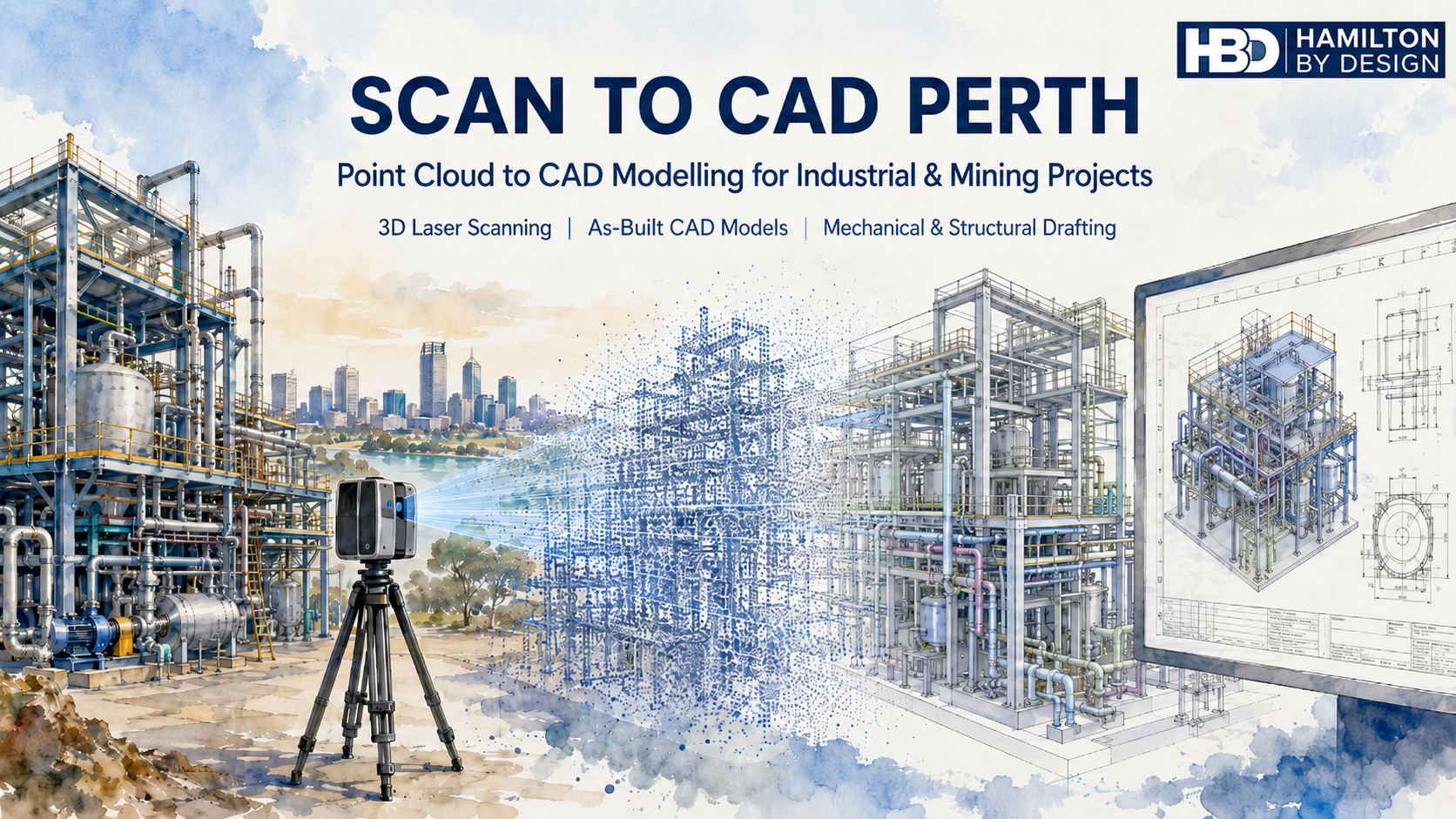
Point Cloud to CAD Modelling for Industrial, Mining and Engineering Projects

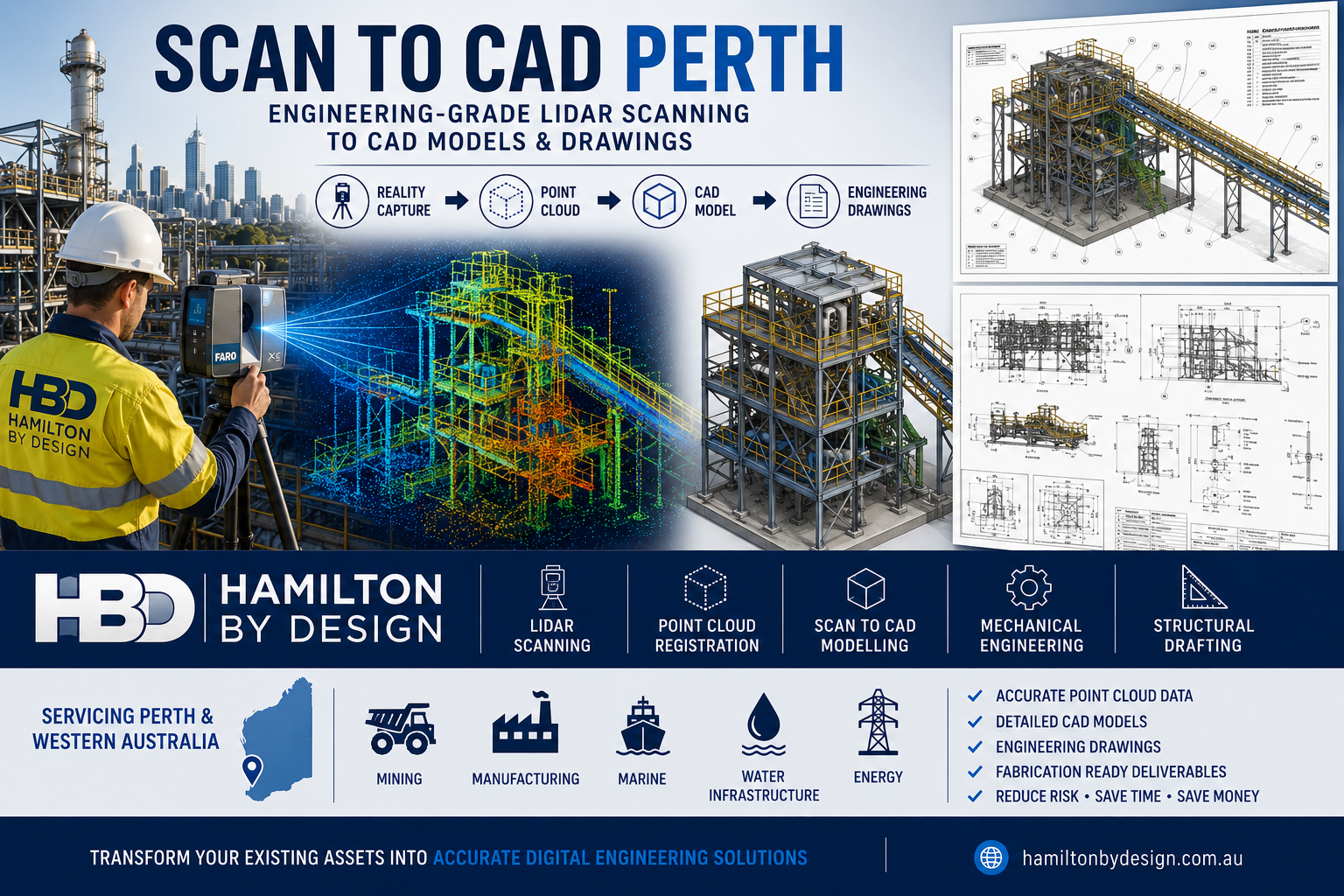
Hamilton By Design provides Scan to CAD Perth services for businesses that need accurate CAD models, drawings and engineering information from existing plant, equipment, structures and sites.
Many Perth and Western Australian businesses work with assets that have been modified over many years. Drawings may be missing, outdated, incomplete or no longer trusted. This creates problems when planning upgrades, replacing equipment, modifying pipework, designing new access platforms or reverse engineering obsolete parts.
Scan to CAD helps solve this problem by converting real-world site conditions into usable CAD data.
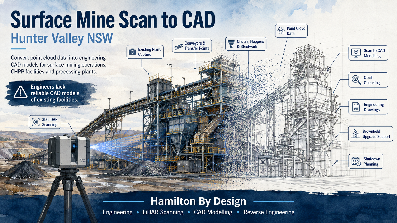
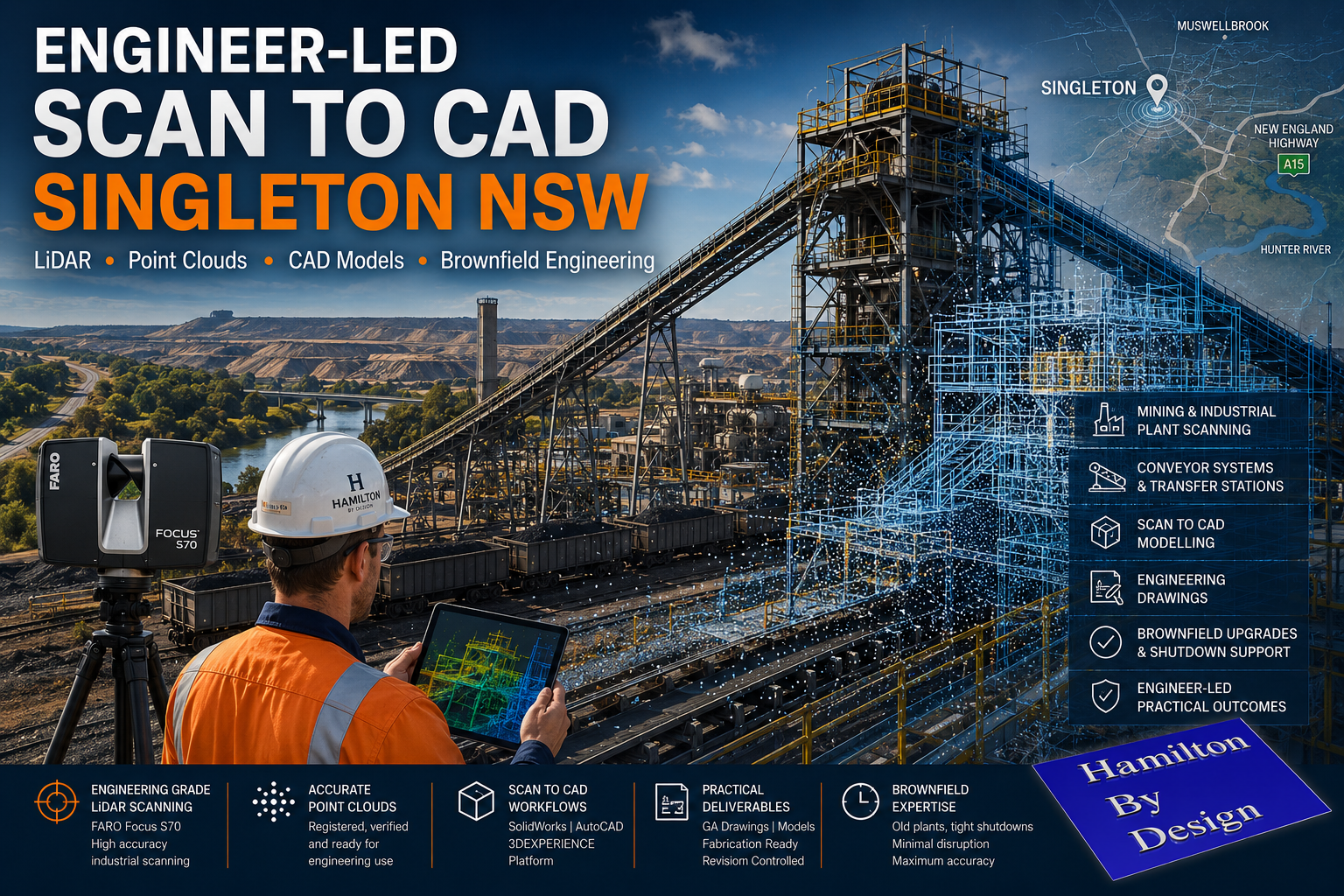
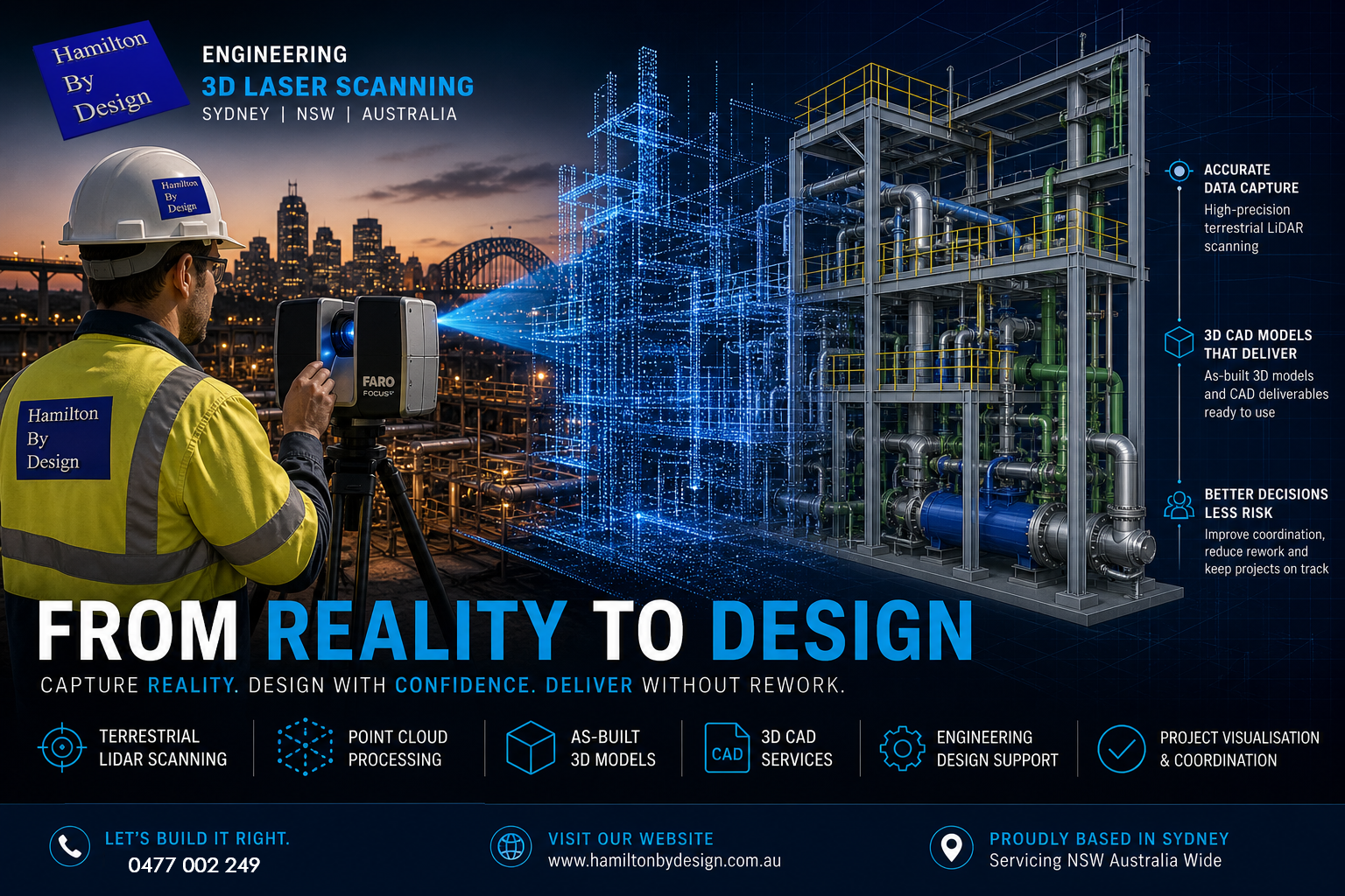
Using 3D laser scanning and LiDAR capture, Hamilton By Design can scan existing assets and convert the point cloud into practical engineering deliverables such as 3D CAD models, 2D drawings, as-built layouts, mechanical models, structural layouts, pipework models and fabrication-ready documentation.
For related Perth services, Hamilton By Design also provides 3D laser scanning in Perth, mechanical engineering services in Perth and SolidWorks CAD support in Perth.
Our Scan to CAD Perth services support mining, industrial, manufacturing, marine, infrastructure, water, energy and process plant projects across Perth and Western Australia.
What Is Scan to CAD?
Scan to CAD is the process of capturing an existing object, machine, structure, plant room, building or industrial site using a 3D laser scanner, then converting the scan data into CAD models or drawings.
The scanner captures millions of measurement points from the real-world environment. This creates a point cloud, which can then be processed, registered and used as a reference for CAD modelling.
The CAD output may be simple or detailed depending on the project.
For example, a business may need a basic 3D layout to check whether new equipment will fit. Another project may require detailed CAD models of pipework, steelwork, access platforms, pump components or mechanical assemblies. In some cases, the final deliverable may be a set of fabrication drawings, general arrangement drawings, sections, elevations or 3D model files for engineering design.
Scan to CAD is especially useful for brownfield projects, where new design work needs to fit around existing assets.
Why Perth Businesses Use Scan to CAD Services
Perth businesses use Scan to CAD services when they need reliable information about existing assets.
This is common in mining, ports, processing plants, fabrication workshops, pump stations, utilities, marine facilities and industrial sites. Many of these sites have been changed over many years. Equipment has been replaced, pipework has been rerouted, structures have been modified and old drawings may not reflect the current condition.
When drawings cannot be trusted, engineering work becomes risky.
A new piece of equipment may clash with existing steelwork. A replacement pipe spool may not fit. A platform may be designed around incorrect dimensions. A shutdown job may be delayed because the site information was wrong. These problems can cost far more than the original drafting or scanning work.
Scan to CAD helps reduce this risk by giving engineers, project managers, fabricators and maintenance teams a clearer understanding of the existing site before design, fabrication or installation begins.
For larger Perth and WA projects, this service can also connect with Hamilton By Design’s broader Perth WA engineering and 3D scanning services.
Common Problems Scan to CAD Helps Solve
One of the biggest problems businesses face is the lack of reliable drawings. In many industrial environments, original drawings are either unavailable or no longer accurate. This is particularly common where plant has been upgraded over many years without the as-built documentation being updated.
Another common problem is that OEM drawings are not available. Equipment suppliers may not provide drawings, or replacement parts may have long lead times and high costs. In these situations, Scan to CAD can assist with reverse engineering by capturing the existing part or assembly and creating CAD models for review, repair, modification or replacement.
Brownfield upgrades are another major reason for using Scan to CAD. Existing structures, conveyors, chutes, tanks, pumps, platforms, walkways and pipework can make new design work difficult. A scan provides a practical way to model the existing environment and check the proposed design before fabrication.
Shutdown work is also a key driver. During a shutdown, there is limited time to complete installation work. If a fabricated part does not fit, the cost can be significant. Scan to CAD helps reduce the chance of site rework, emergency fabrication and installation delays.
Scan to CAD for Mining and Industrial Sites in Perth
Perth is closely connected to Western Australia’s mining, resources, marine, energy and industrial sectors. Many projects are designed, managed or supported from Perth, even when the site itself is located elsewhere in WA.
Hamilton By Design supports Scan to CAD services for mining and industrial applications including:
Conveyors, chutes and transfer points.
Pump stations and pipework.
Processing plants and fixed plant equipment.
Access platforms, stairs, ladders and walkways.
Structural steel layouts.
Mechanical equipment and machine components.
Plant rooms and service areas.
Marine and ship repair projects.
Brownfield upgrade areas.
Reverse engineering of obsolete or unavailable parts.
The purpose is not only to create a point cloud. The purpose is to turn that scan data into useful engineering information.
For projects involving steelwork, platforms, pipework or industrial layouts, Hamilton By Design also provides mechanical, structural and pipework drafting in Perth WA.
From Point Cloud to Practical CAD Deliverables
A point cloud is valuable, but many businesses need more than raw scan data. They need usable CAD information that can support decisions, design work, procurement, fabrication and installation.
Hamilton By Design can convert point cloud data into a range of CAD deliverables, including:
3D CAD models.
2D CAD drawings.
General arrangement drawings.
Sections and elevations.
As-built layouts.
Pipework models.
Structural models.
Mechanical models.
STEP, SAT or Parasolid files.
SolidWorks models.
Inventor models.
AutoCAD drawings.
DWG and DXF files.
Fabrication drawings where required.
The final deliverable depends on the project requirement. A clash detection model may not need the same level of detail as a fabrication drawing. A concept model may not need every bolt and weld. A reverse engineering job may need a much higher level of detail.
This is why it is important to define the scope before scanning and modelling begins.
The Importance of Engineering Understanding
Scan to CAD is not just a software process. It requires engineering judgement.
A scanner records what it can see, but the CAD model needs to be interpreted and built by someone who understands the purpose of the work. This is especially important for mechanical, structural and industrial projects.
For example, pipework may need to be modelled using correct pipe outside diameters and centre lines. Steelwork may need to reflect real member sizes. Platforms and access systems may need to consider Australian Standards such as AS 1657. Mechanical components may need to be modelled with design intent, clearances, tolerances and manufacturing method in mind.
A visually impressive model is not always an engineering-ready model.
Hamilton By Design focuses on practical CAD outputs that can be used by engineers, fabricators, project managers and maintenance teams.
Problems Businesses Can Have With Poor Scan to CAD Services
Not all Scan to CAD services are the same.
A common problem is that businesses receive a large point cloud but do not know how to use it. The file may be too large, the format may not suit their software, or the areas they need may not have been captured properly.
Another problem is unclear scope. If the instruction is only “scan the site and provide CAD”, the result may not match what the business expected. The scope should define what needs to be scanned, what needs to be modelled, the required level of detail, the accuracy expectations, the required file formats and whether drawings are included.
Businesses can also run into trouble when the model is either under-modelled or over-modelled. Under-modelling can miss important details. Over-modelling can waste time and increase cost without adding value.
There can also be line-of-sight issues. Laser scanners cannot see through objects, insulation, guards, cladding or equipment. Hidden areas may require extra scan positions, physical measurement or site verification.
The best results come from planning the scan around the final CAD deliverable.
When Should Scan to CAD Be Used?
Scan to CAD should be considered early in a project, especially when existing information is unreliable.
It is useful before:
Plant upgrades.
Equipment installation.
Shutdown planning.
Pipework replacement.
Structural modification.
Access platform design.
Reverse engineering.
Fabrication.
Clash detection.
Layout planning.
As-built documentation.
The earlier the scan is completed, the more useful it becomes. If the scan is done after design work is already finished, it may only reveal problems late in the project. When scanning is completed early, the design team can work around the real site conditions from the start.
Scan to CAD Perth for Brownfield Engineering
Brownfield engineering is one of the strongest applications for Scan to CAD.
In a brownfield site, the challenge is not simply designing something new. The challenge is making sure the new design fits the existing plant.
This is where Scan to CAD provides value.
By converting existing site conditions into CAD, Hamilton By Design can help identify space restrictions, clashes, tie-in points, access limitations and installation constraints before work reaches site.
This can support better planning, better design decisions and reduced installation risk.
For businesses needing building, facility or infrastructure modelling from scan data, Hamilton By Design also provides Scan to BIM services in Perth WA.
Why Work With Hamilton By Design?
Hamilton By Design combines 3D laser scanning, CAD modelling, mechanical engineering, structural drafting and reverse engineering experience.
This means the Scan to CAD process is approached with the final engineering outcome in mind.
We understand that businesses do not simply need a scan. They need answers.
Will the new equipment fit?
Can the part be reverse engineered?
Can the pipework be modelled accurately?
Can the existing structure be documented?
Can the shutdown risk be reduced?
Can the CAD model be used for design, drafting or fabrication?
Our goal is to provide practical CAD information that helps businesses make better engineering decisions.
Scan to CAD Perth Services
Hamilton By Design provides Scan to CAD Perth services for businesses needing accurate, useful and engineering-focused CAD deliverables from existing assets.
Whether the project involves mining equipment, industrial plant, pipework, structural steel, mechanical components, marine repairs or brownfield upgrades, Scan to CAD can help turn site reality into usable engineering data.
If your business has missing drawings, unreliable site information, obsolete parts, shutdown risk or brownfield design challenges, Scan to CAD may be the right starting point.
Hamilton By Design can assist with 3D laser scanning, point cloud processing, CAD modelling, as-built documentation and engineering drafting for Perth and Western Australian projects.

Need Scan to CAD Support in Perth?
Hamilton By Design provides Scan to CAD services for Perth businesses that need accurate CAD models and drawings from existing plant, equipment and structures.
We can assist with site scanning, point cloud processing, CAD modelling, as-built drawings, reverse engineering and engineering documentation for industrial and mechanical projects.
Talk to Us – Contact Us
Our clients: