3D Scanning for Engineering in Mining โ€“ Equipment, Chutes, Conveyors and Plant Upgrades

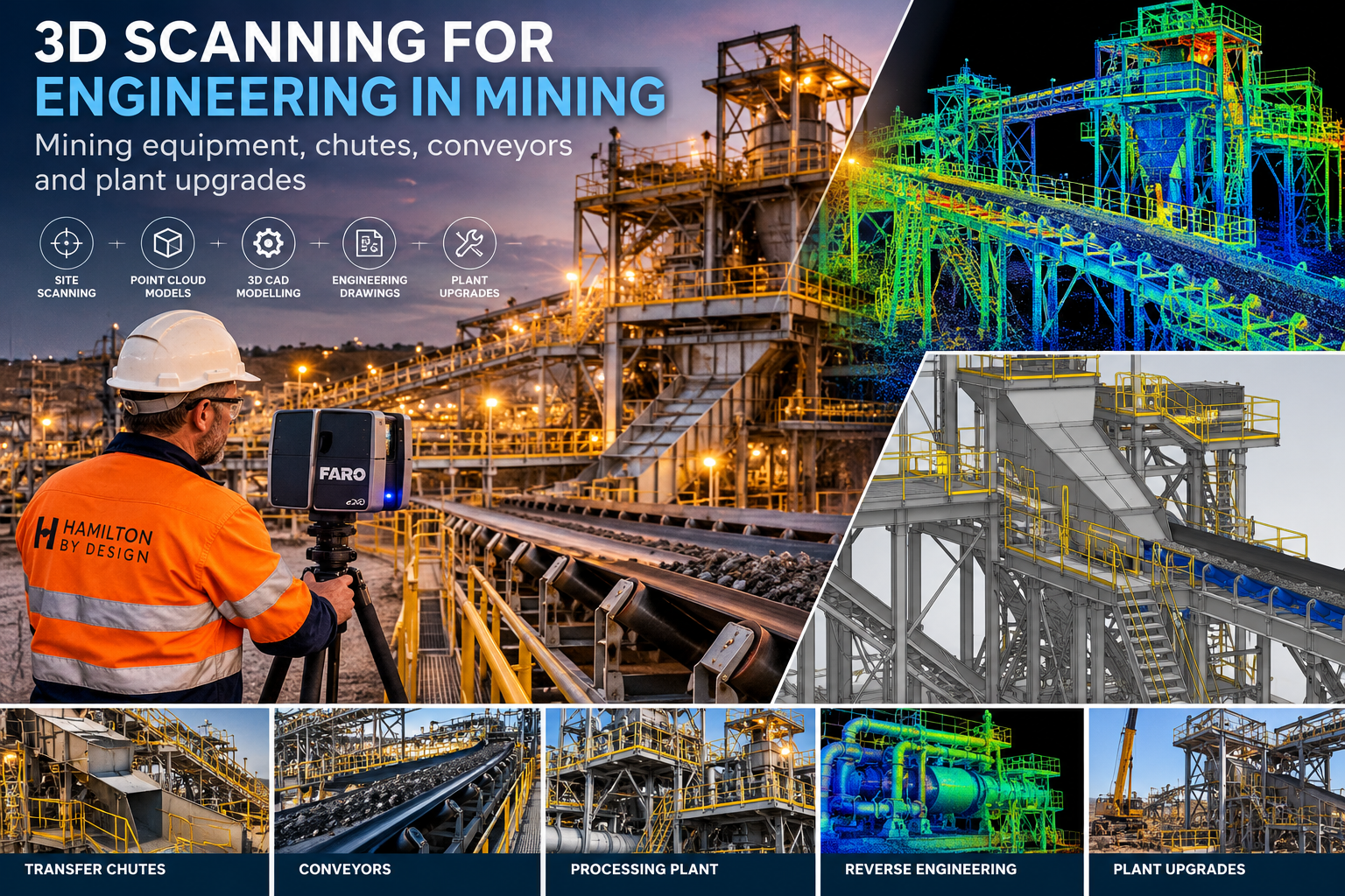
3D scanning for engineering in mining showing FARO LiDAR scanning, transfer chutes, conveyors, point clouds, CAD modelling and processing plant upgrades.

Reducing installation uncertainty through accurate site measurement, 3D modelling and practical mechanical engineering.

Supporting Mining Engineering with 3D Scanning

Blue 3D LiDAR scanner icon on a tripod with scanning waves

Mining operations depend on equipment that must perform reliably under demanding operating conditions. Conveyors, transfer chutes, processing equipment, pumps, pipework and structural interfaces are frequently modified as production requirements change.

However, engineering modifications can become difficult when existing drawings are incomplete, equipment has been altered or the actual installed geometry differs from the original design.

Hamilton By Design provides 3D scanning for engineering in mining, combining LiDAR measurement, point cloud processing, 3D CAD modelling and mechanical engineering support.

Our services assist mining companies, maintenance teams, engineering contractors and fabrication workshops in understanding existing plant conditions before undertaking equipment upgrades.

By capturing the physical arrangement of equipment and surrounding structures, we help identify spatial constraints, develop suitable modifications and reduce the risk of installation problems during planned shutdowns.

Why 3D Scanning Matters in Mining Engineering

Mining processing plants are continually evolving. Over time, equipment may be replaced, conveyor alignments adjusted, platforms modified and pipework rerouted.

Traditional drawings may no longer accurately represent these changes.

3D LiDAR scanning provides a digital record of accessible existing plant geometry, allowing engineers to investigate proposed modifications using measured information rather than relying entirely on assumptions.

Typical engineering challenges include:

  • Replacement chutes that must connect to existing conveyors.
  • New equipment installed within congested processing areas.
  • Conveyor modifications involving existing transfer points.
  • Pump and pipework upgrades with limited installation space.
  • Equipment access and maintenance clearance requirements.
  • Plant modifications where original drawings are unavailable.
  • Shutdown projects requiring fabrication before equipment is removed.

The objective is not simply to produce a point cloud. It is to turn measured site information into useful engineering decisions.

Mining Equipment, Chutes, Conveyors and Plant Upgrades

1. Transfer Chute Design and Replacement

Transfer chutes are critical components of mining and bulk material handling systems. Their performance depends on the relationship between conveyor discharge geometry, material flow, wear protection and the surrounding equipment.

When an existing chute requires replacement, the installed arrangement may differ from the original drawings.

3D scanning can capture conveyor discharge points, receiving belts, existing chute connections and surrounding structures.

This information supports:

  • Replacement chute geometry and design.
  • Existing flange and connection arrangements.
  • Wear liner layouts and replacement planning.
  • Maintenance access and inspection provisions.
  • Fabrication and installation drawings.
  • Interference checks with surrounding equipment.

While scanning establishes the existing geometry, engineering assessment is still required to consider material flow, impact loading, wear characteristics and structural performance.

2. Conveyor Modifications and Upgrades

Conveyor systems are frequently modified to improve production, replace ageing components or accommodate changes in processing requirements.

These modifications may involve existing drive arrangements, transfer stations, support structures, guarding and access platforms.

3D scanning can capture the installed conveyor arrangement and surrounding plant geometry.

The resulting point cloud can be used to develop 3D models that support:

  • Conveyor transfer point modifications.
  • Drive and pulley arrangement changes.
  • Conveyor guarding and access improvements.
  • Replacement equipment installation.
  • Support structure interfaces.
  • Equipment clearance assessments.
  • General arrangement and fabrication drawings.

Using measured plant geometry during the design stage helps identify potential installation conflicts before fabrication begins.

3. Mining Equipment and Processing Plant Upgrades

Mining processing facilities contain interconnected mechanical systems where even relatively small modifications can affect surrounding equipment.

Replacing a pump, installing a new skid or modifying pipework may require careful consideration of existing connection points, structural supports and available access.

3D scanning supports these projects by establishing a spatial reference for the existing plant.

Applications include:

  • Pump and mechanical equipment replacement.
  • Pipework modifications and rerouting.
  • Equipment skid design.
  • Processing equipment upgrades.
  • Existing plant layout development.
  • Maintenance access improvements.
  • Mechanical equipment reverse engineering.

Hamilton By Design can use the captured information to develop CAD models and engineering drawings for proposed modifications.

4. Mobile Mining Equipment and Wear Assessment

Mobile mining equipment operates in demanding environments where wear, impact and material handling conditions influence component life.

Haul truck trays, loader buckets and other equipment may require dimensional assessment when planning repairs, replacement components or wear protection systems.

3D scanning can support the measurement of accessible equipment surfaces and the development of digital geometry for engineering review.

Applications may include:

  • Haul truck tray geometry assessment.
  • Loader bucket wear and dimensional comparisons.
  • Wear liner replacement planning.
  • Reverse engineering of existing components.
  • Assessment of geometric changes.
  • Development of repair and modification drawings.

Wear assessment should consider operating conditions, material characteristics, duty cycles and engineering requirements rather than relying on geometric measurements alone.

From 3D Scanning to Engineering Drawings

Hamilton By Design combines site measurement with mechanical engineering and drafting services.

Our approach supports projects from the initial site survey through to engineering models and fabrication documentation.

Stage 1 โ€“ Capture Existing Plant Conditions

Using terrestrial 3D LiDAR scanning equipment, accessible equipment, structures and surrounding plant areas are captured to create a point cloud dataset.

The survey scope is established according to the engineering requirements, including critical connection points, equipment interfaces and areas where installation clearances must be verified.

Stage 2 โ€“ Point Cloud Registration and Processing

Individual scans are registered into a coordinated dataset representing the surveyed plant.

The point cloud can be reviewed and prepared for use in CAD and plant coordination environments.

Typical deliverables may include E57, RCP and other agreed point cloud formats.

Stage 3 โ€“ Develop the Engineering Model

The captured geometry is used to develop 3D CAD models of relevant existing equipment and proposed modifications.

Depending on the project, this may include SolidWorks modelling, equipment layouts, mechanical assemblies and plant coordination models.

Stage 4 โ€“ Engineering Review and Design Development

Proposed modifications can be assessed for geometric compatibility, maintenance access, installation constraints and equipment interfaces.

Where required, separate engineering assessments may address structural loads, mechanical performance, material flow or fatigue.

Stage 5 โ€“ Prepare Drawings for Fabrication

Following design review and approval, general arrangement drawings, component details and fabrication documentation can be developed.

Critical dimensions, tolerances and connection details should be independently verified where necessary before fabrication.

Reducing Mining Shutdown Risk with 3D Scanning

Mining shutdowns are often planned around limited installation windows. Equipment may need to be fabricated before existing components are removed, making dimensional uncertainty a significant project risk.

A replacement chute, for example, may need to connect to existing steelwork, conveyor discharge points and receiving equipment.

If the original drawings do not reflect the installed arrangement, dimensional discrepancies may only become apparent during installation.

3D scanning can reduce this uncertainty by providing a measured reference for engineering design.

Potential benefits include:

  • Earlier identification of geometric conflicts.
  • Reduced reliance on outdated drawings.
  • Improved planning for prefabricated components.
  • Better understanding of installation and access constraints.
  • Fewer avoidable site modifications.
  • More informed shutdown planning.
  • Improved coordination between engineers, fabricators and site maintenance teams.

3D scanning does not eliminate installation risk. The suitability of the captured data must be assessed against the required fabrication and assembly tolerances. Critical interfaces may require supplementary dimensional measurements.

Engineering Applications Across Mining Operations

Hamilton By Design’s scanning and mechanical engineering capabilities can support a range of mining environments throughout Australia.

Coal Handling and Preparation Plants

3D scanning can support transfer chute replacement, conveyor modifications, screening equipment upgrades and mechanical plant improvements.

Existing plant geometry can be used to develop replacement components and evaluate their integration with surrounding equipment.

Copper and Gold Processing Plants

Processing plant upgrades may involve pumps, pipework, conveyors, mechanical equipment and access structures.

Scanning provides spatial information that can assist with equipment replacement, design coordination and installation planning.

Mineral Sands Processing Facilities

Mineral sands operations often involve conveyors, transfer points, separation equipment and associated mechanical infrastructure.

3D scanning can support plant modifications where new equipment must connect to existing systems.

Underground Mining Infrastructure

Where access and operating conditions permit, 3D scanning can support mechanical equipment arrangements, service interfaces and infrastructure modifications.

Mobile Equipment Maintenance Facilities

Scanning and reverse engineering can assist with equipment geometry, replacement component development and dimensional assessment of worn components.

Bulk Material Handling Facilities

Conveyors, transfer stations, chutes and supporting mechanical equipment can be measured to support replacement, maintenance and plant upgrade projects.

3D Scanning Compared with Traditional Site Measurement

Traditional measurement remains valuable, particularly for critical dimensions and precision interfaces.

However, complex mining equipment arrangements can be difficult to document using individual measurements alone.

3D LiDAR scanning captures broader spatial information, allowing engineers to review equipment relationships within a coordinated digital environment.

For example, a conveyor transfer station may include multiple structural members, drive equipment, guarding, platforms and chute interfaces.

Capturing the surrounding arrangement can provide a more complete understanding of the available space.

The strongest engineering outcome often comes from combining 3D scanning with conventional dimensional verification and practical engineering judgement.

Why Choose Hamilton By Design for Mining Engineering?

Hamilton By Design provides a combination of 3D scanning, mechanical engineering, CAD modelling and fabrication documentation.

This integrated approach means scanning information can be used directly in the development of practical engineering solutions.

Our capabilities include:

  • FARO terrestrial 3D LiDAR scanning.
  • Point cloud registration and processing.
  • SolidWorks and AutoCAD modelling.
  • Mechanical equipment and conveyor design.
  • Transfer chute development and modifications.
  • Reverse engineering of existing components.
  • Fabrication and general arrangement drawings.
  • Plant coordination and shutdown engineering support.
  • Mechanical equipment installation and fit-up assessments.

Rather than treating scanning as an isolated surveying activity, Hamilton By Design focuses on how the measured information can support engineering decisions.

Projects can be scoped as scanning-only services or as broader engineering assignments involving measurement, design development and documentation.

Frequently Asked Questions

Can 3D scanning be used to design replacement mining chutes?

Yes. Scanning can capture the existing conveyor and chute arrangement to support replacement design.

Critical interfaces, material flow requirements, impact loading and mechanical design parameters must also be considered.

Can 3D scanning reduce mining shutdown delays?

3D scanning can help reduce delays associated with unknown geometry, component clashes and avoidable fit-up problems.

However, the outcome depends on survey coverage, measurement quality, engineering verification and project planning.

Can you develop SolidWorks models from point clouds?

Yes. Hamilton By Design can use point cloud information as a reference to develop SolidWorks models of existing equipment and proposed mechanical modifications.

These models can support design development, equipment arrangements and fabrication documentation.

What if the original plant drawings are unavailable?

3D scanning can establish a measured geometric reference for accessible existing equipment.

Additional measurements and engineering investigation may still be necessary to establish critical dimensions, hidden features and equipment requirements.

Is 3D LiDAR scanning accurate enough for fabrication?

Accuracy depends on the scanner, measurement range, surface conditions, registration quality and measurement method.

Critical fabrication dimensions should be checked against the project tolerance requirements and verified using appropriate measurement instruments.

Can Hamilton By Design assist with mining projects outside NSW?

Yes. Hamilton By Design can provide project-based scanning and mechanical engineering services across Australia, subject to project scope, site access and mobilisation arrangements.

Plan Your Next Mining Plant Upgrade with Greater Confidence

Whether you are replacing a transfer chute, modifying a conveyor, installing equipment or developing a new plant layout, understanding the existing geometry is an important first step.

Hamilton By Design can assist with site scanning, point cloud processing, mechanical design, 3D modelling and engineering drawings.

Our approach combines accurate measurement with practical mechanical engineering to help mining operators and contractors plan equipment modifications with greater confidence.

From site scanning to engineering models and fabrication drawings, Hamilton By Design helps turn existing plant geometry into practical engineering solutions.

Contact Hamilton By Design to discuss your next mining equipment, conveyor, transfer chute or processing plant upgrade.


Hamilton By Design logo displayed on a blue tilted rectangle with a grey gradient background

Contact Us – Talk To Us

Name
Would you like us to arrange a phone consultation for you?
Address

Our clients:


3D LiDAR Scanning Narrabri Gas Project โ€“ Supporting Coal Seam Gas Infrastructure Development

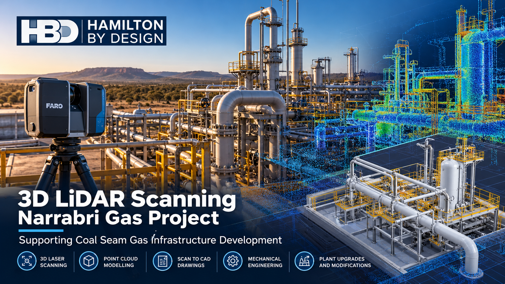
3D LiDAR scanning Narrabri Gas Project illustration showing FARO laser scanner, coal seam gas processing infrastructure, point cloud modelling and mechanical engineering by Hamilton By Design.

3D Laser Scanning | Mechanical Engineering | Gas Infrastructure | Scan-to-CAD | Narrabri NSW

Supporting Coal Seam Gas Infrastructure Development in Narrabri, NSW

The Narrabri Gas Project, located in the Pilliga region of north-western New South Wales, represents a significant proposed development within Australia’s onshore natural gas industry.

Operated by Santos, the project involves the development of coal seam gas resources and associated infrastructure to support natural gas supply.

The planning, construction, operation and maintenance of gas infrastructure require accurate spatial information, coordinated engineering design and reliable equipment interfaces.

Blue 3D LiDAR scanner icon on a tripod with scanning waves

Hamilton By Design provides 3D LiDAR scanning, mechanical engineering, 3D modelling and scan-to-CAD services to support industrial infrastructure projects across regional New South Wales and Australia.

Our services can assist engineering contractors, equipment suppliers and infrastructure developers working on projects such as the Narrabri Gas Project.

By capturing existing site conditions and converting point cloud information into practical engineering models, we help reduce dimensional uncertainty, improve design coordination and minimise the risk of costly fabrication and installation errors.

Why 3D LiDAR Scanning Matters for Coal Seam Gas Infrastructure

Coal seam gas developments can involve geographically distributed infrastructure, including gas gathering networks, processing facilities, compression equipment, pipework, pumps, access platforms and associated mechanical systems.

As infrastructure develops, accurate information about equipment locations, pipework connections and available space becomes increasingly important.

Traditional site measurements may not capture the full complexity of an industrial installation, particularly where multiple contractors are responsible for different engineering packages.

3D LiDAR scanning provides a detailed digital representation of accessible infrastructure and surrounding conditions.

This information can be used to support:

  • Existing-condition surveys before engineering design
  • Pipework routing and mechanical equipment installation
  • Compressor and pump skid modifications
  • Structural and mechanical interface coordination
  • Equipment replacement and upgrade planning
  • Fabrication drawing development
  • Maintenance access and equipment clearance assessments
  • Construction planning and installation verification

For the Narrabri region, these capabilities can assist both new infrastructure development and future operational modifications.

1. 3D LiDAR Scanning for Gas Processing Facilities

Gas processing and treatment facilities can contain closely spaced equipment, pipework, valves, support structures and maintenance access areas.

Accurate measurement of these installations is essential when designing new equipment or modifying existing systems.

Hamilton By Design uses terrestrial 3D laser scanning to capture accessible industrial environments and produce registered point cloud datasets.

These datasets can provide engineers and contractors with a digital reference for equipment positions, elevations, clearances and surrounding infrastructure.

Potential applications include:

  • Gas treatment equipment layouts
  • Pipework and valve station surveys
  • Compressor station equipment arrangements
  • Mechanical equipment foundations and interfaces
  • Access platforms and maintenance walkways
  • Existing equipment replacement
  • Brownfield plant modification planning

Using point cloud information during design can help identify spatial conflicts before equipment reaches the construction site.

2. Scan-to-CAD for Gas Infrastructure Engineering

Collecting point cloud data is only the first stage of an effective engineering workflow.

The information must be converted into usable engineering geometry to support design decisions, fabrication and construction.

Hamilton By Design provides scan-to-CAD services using software including SolidWorks, AutoCAD, Autodesk ReCap and Navisworks.

Depending on project requirements, deliverables can include:

  • Registered 3D point clouds
  • 3D mechanical equipment models
  • Pipework routing models
  • General arrangement drawings
  • Equipment interface drawings
  • Fabrication and installation drawings
  • STEP and Parasolid files
  • Navisworks-compatible coordination models

This approach allows engineers to develop modifications around actual site geometry rather than relying entirely on historical drawings.

For coal seam gas infrastructure, scan-to-CAD can be particularly valuable when connecting new mechanical systems to existing equipment.

3. Pipework Routing and Mechanical Interface Verification

Pipework installation can present significant challenges when connection points, equipment positions and available clearances are not accurately established.

Small dimensional discrepancies can create substantial installation problems, particularly where prefabricated pipe spools must connect to fixed equipment.

Hamilton By Design can assist with 3D modelling and mechanical design to assess proposed pipework routes against captured site conditions.

Applications may include:

  • Gas gathering and process pipework interfaces
  • Compressor suction and discharge pipework
  • Pump and utility pipework
  • Pipe support arrangements
  • Valve access and maintenance clearances
  • Pipe spool interface verification
  • Mechanical equipment connection points

A coordinated 3D model can help establish whether proposed pipework fits within the available space before fabrication begins.

Where required, additional engineering analysis can be undertaken to assess mechanical loads, supports and equipment interfaces.

Pressure containment design, hazardous-area requirements and statutory approvals must be addressed by appropriately qualified specialists.

4. Mechanical Engineering for Compressor and Pump Installations

Coal seam gas infrastructure may require mechanical equipment such as compressors, pumps, filtration systems and associated support arrangements.

Installing or modifying these systems requires careful consideration of equipment geometry, maintenance access and mechanical interfaces.

Hamilton By Design provides mechanical design and drafting services for industrial equipment installations.

Potential services include:

  • Compressor and pump skid layouts
  • Equipment support frames
  • Baseplate and mounting arrangements
  • Mechanical equipment guarding
  • Maintenance access provisions
  • Equipment replacement studies
  • Mechanical component reverse engineering
  • General arrangement and fabrication drawings

Our mechanical engineering approach combines site measurement, 3D modelling and practical fabrication considerations.

The objective is to develop solutions that can be manufactured, transported, installed and maintained with reduced uncertainty.

5. Reducing Construction and Installation Risk

One of the greatest challenges in industrial construction is discovering dimensional conflicts after equipment has already been fabricated.

Incorrect assumptions about existing infrastructure can lead to:

  • Pipe spools requiring modification
  • Equipment mounting holes failing to align
  • Insufficient maintenance access
  • Interference between new and existing services
  • Additional site welding or fabrication
  • Construction delays and rework
  • Increased project costs

3D LiDAR scanning can reduce these risks by providing a more complete record of accessible existing conditions.

For infrastructure developments around Narrabri, early scanning and model coordination can assist engineering teams in identifying potential conflicts before fabrication or installation.

The objective is straightforward: measure the existing conditions, model the proposed installation and verify the fit before construction.

6. Digital Engineering and Point Cloud Coordination

Large infrastructure developments often involve several engineering disciplines and contractors working from different design information.

Maintaining consistency between these information sources is important for effective project delivery.

Hamilton By Design can support digital engineering workflows through registered point clouds, 3D mechanical models and coordinated drawing packages.

These datasets can be incorporated into broader engineering and construction models to assist with:

  • Multidisciplinary design reviews
  • Mechanical equipment coordination
  • Construction sequencing
  • Spatial clash identification
  • Maintenance planning
  • Asset modification studies
  • Digital asset documentation

Point cloud information also provides a valuable baseline for future engineering work.

As infrastructure changes, updated surveys can be compared with previous datasets to support ongoing asset management.

7. Supporting Brownfield Modifications and Future Maintenance

Although new infrastructure development receives significant attention, long-term asset performance also depends on maintenance, equipment replacement and plant upgrades.

Industrial facilities commonly undergo modifications throughout their operating lives.

Equipment may be replaced, pipework altered, access platforms modified or new mechanical systems introduced.

These activities benefit from accurate records of existing conditions.

Hamilton By Design can assist maintenance and engineering teams by capturing accessible equipment geometry and developing models for proposed modifications.

This is particularly useful when historical drawings are incomplete, outdated or inconsistent with the installed equipment.

By combining 3D scanning with mechanical engineering, we help bridge the gap between site conditions and practical design deliverables.

8. Supporting Engineering Contractors Across the Narrabri Region

Hamilton By Design provides project-based engineering and 3D scanning services across New South Wales, including regional and remote industrial locations.

For the Narrabri Gas Project and surrounding infrastructure developments, our services may be relevant to:

  • Engineering, procurement and construction contractors
  • Mechanical installation contractors
  • Gas infrastructure developers
  • Pipework fabrication companies
  • Compressor and pump equipment suppliers
  • Industrial maintenance providers
  • Mechanical engineering consultancies
  • Asset owners and operators

Our involvement can range from a targeted site scanning assignment to a complete scan-to-CAD and mechanical design package.

We can also work alongside existing engineering teams to provide supplementary modelling, drafting and dimensional verification support.

9. Our 3D Scanning and Engineering Workflow

Hamilton By Design follows a practical workflow that connects site measurement with engineering deliverables.

Stage 1 โ€“ Define the Scope

Establish the equipment, structures or infrastructure requiring measurement, including the intended engineering use of the data.

Stage 2 โ€“ Capture Existing Conditions

Undertake 3D LiDAR scanning of accessible infrastructure using suitable survey positions and site controls.

Stage 3 โ€“ Register and Process the Point Cloud

Combine scan positions into a coordinated dataset and review coverage, registration quality and relevant dimensional limitations.

Stage 4 โ€“ Develop the 3D Engineering Model

Convert relevant point cloud information into mechanical equipment models, pipework geometry or general arrangement models.

Stage 5 โ€“ Review Proposed Modifications

Assess equipment positions, connection interfaces, access clearances and potential spatial conflicts.

Stage 6 โ€“ Prepare Engineering Deliverables

Produce agreed 3D models, drawings and coordination files for design review, fabrication planning or construction.

This integrated approach supports more informed engineering decisions and reduces dependence on assumptions about existing infrastructure.

10. Why Choose Hamilton By Design?

Hamilton By Design combines practical mechanical engineering experience with 3D laser scanning and digital modelling capabilities.

Our services are particularly suited to industrial environments where accurate dimensional information is essential for equipment modification and installation.

Our capabilities include:

  • FARO terrestrial 3D laser scanning
  • Point cloud registration and processing
  • SolidWorks mechanical modelling
  • AutoCAD engineering drafting
  • Scan-to-CAD and reverse engineering
  • Mechanical equipment and skid design
  • Pipework routing and interface modelling
  • Fabrication and general arrangement drawings
  • Navisworks model coordination
  • Mechanical engineering support for industrial upgrades

By integrating scanning and mechanical design, we provide a practical connection between physical infrastructure and engineering documentation.

Frequently Asked Questions

Can 3D LiDAR scanning support coal seam gas infrastructure development?

Yes. 3D LiDAR scanning can capture existing equipment, structures and accessible pipework to support engineering design, installation planning and dimensional verification. It is particularly useful where new equipment must connect to existing infrastructure.

Can Hamilton By Design scan compressor stations and gas processing facilities?

Hamilton By Design can undertake 3D scanning of suitable industrial infrastructure, subject to site access, safety requirements and equipment suitability. Hazardous-area classification and operating conditions must be assessed before scanning.

Can point clouds be converted into SolidWorks models?

Yes. Hamilton By Design can use registered point cloud information to develop SolidWorks models of mechanical equipment, supports, pipework and other relevant infrastructure.

Can 3D scanning help reduce pipework installation problems?

Yes. Accurate scanning can help establish connection positions, available clearances and equipment interfaces before pipe spools are fabricated. This can reduce dimensional uncertainty and the risk of installation rework.

Does Hamilton By Design provide mechanical engineering services as well as scanning?

Yes. Services include mechanical equipment design, 3D modelling, reverse engineering, general arrangement drawings and fabrication documentation.

Can Hamilton By Design work with engineering contractors in Narrabri?

Yes. Hamilton By Design provides project-based engineering and scanning services throughout regional New South Wales, subject to scope, scheduling and site requirements.

What files can be supplied following a 3D scanning project?

Depending on project requirements, deliverables may include E57, RCP and LAS point cloud files, SolidWorks models, STEP files, Parasolid files, DXF drawings and PDF engineering documentation.

Is Hamilton By Design involved directly in the Narrabri Gas Project?

This page describes services potentially relevant to the Narrabri Gas Project and similar gas infrastructure developments. It does not represent a claim of an existing contract or project appointment with Santos.

3D LiDAR Scanning and Mechanical Engineering โ€“ Narrabri NSW

Accurate existing-condition information can make a significant difference to the successful delivery of mechanical equipment installations and infrastructure modifications.

For engineering contractors and infrastructure developers involved in coal seam gas facilities around Narrabri, Hamilton By Design offers a combination of 3D LiDAR scanning, scan-to-CAD and mechanical engineering services.

Whether the requirement involves a compressor skid, pipework interface, equipment replacement or a wider plant survey, our approach focuses on providing reliable geometry and practical engineering deliverables.

Reduce installation uncertainty. Improve engineering coordination. Verify equipment fit before fabrication.

Contact Hamilton By Design

Discuss your 3D scanning, mechanical engineering or infrastructure modelling requirements.

Website: https://www.hamiltonbydesign.com.au/

Service area: Narrabri, Pilliga, north-western NSW and regional Australia.

Hamilton By Design is an independent engineering services provider. References to the Narrabri Gas Project and Santos are for industry and location context only and do not imply an existing commercial relationship, endorsement or project appointment.


Hamilton By Design logo displayed on a blue tilted rectangle with a grey gradient background

Contact Us – Talk To Us

Name
Would you like us to arrange a phone consultation for you?
Address

Our clients:


3D LiDAR Scanning Tamarama โ€“ Precision for High-Value Home Renovations and Architectural Extensions

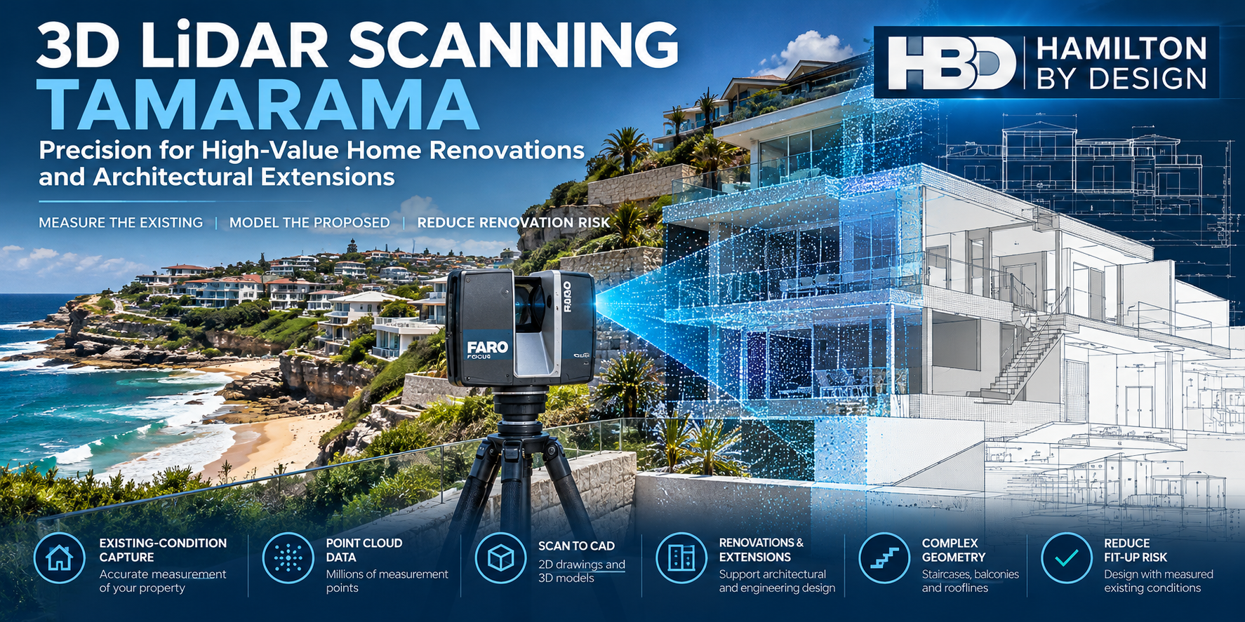
3D LiDAR scanning Tamarama Sydney showing a FARO laser scanner capturing a coastal home, with point cloud data and architectural CAD modelling overlays.

Accurate Existing-Condition Measurements Before You Renovate

Planning a renovation, home extension or architectural alteration in Tamarama?

Blue 3D LiDAR scanner icon on a tripod with scanning waves

Hamilton By Design provides professional 3D LiDAR scanning in Tamarama, Sydney, helping homeowners, architects, builders and designers understand the existing geometry of residential buildings before design and construction begin.

Using terrestrial laser scanning technology, we capture millions of three-dimensional measurement points to create a digital record of accessible building surfaces.

This information can be used to develop point clouds, 2D drawings and 3D CAD models for architectural planning, engineering coordination and building modifications.

Whether you are extending an established coastal residence, modifying a multi-level home or preparing documentation for a major renovation, understanding the existing building is an important first step.

Measure the existing building. Reduce assumptions. Design with greater confidence.

Why 3D Laser Scanning Is Valuable for Tamarama Properties

Tamarama is one of Sydney’s distinctive coastal residential suburbs, located between Bondi and Bronte.

With a reported median house sale price of approximately $9 million in 2026, property renovations can involve substantial financial commitments.

High property values do not automatically make every renovation complex. However, where substantial alterations are proposed, inaccurate existing-condition information can create unnecessary design changes, fabrication problems and construction delays.

Tamarama properties may present challenges including:

  • Multi-storey homes constructed on sloping sites.
  • Restricted access between neighbouring buildings.
  • Existing structures with incomplete or outdated drawings.
  • Complex rooflines, balconies, terraces and staircases.
  • Irregular building geometry and changes in floor levels.
  • Architectural alterations requiring accurate dimensional coordination.
  • Coastal exposure and existing construction requiring specialist consideration.
  • Limited space for construction equipment and material handling.

3D LiDAR scanning helps document visible existing geometry before designers commit to proposed modifications.

For renovations involving structural alterations, the scanning information can assist the relevant engineers with geometric coordination. Structural adequacy, material condition and design compliance require separate engineering assessment.

What Is 3D LiDAR Scanning?

3D LiDAR scanning is a non-contact measurement process that uses laser technology to capture the visible geometry of buildings and structures.

A terrestrial laser scanner records millions of spatial measurements from multiple positions.

These measurements are combined into a registered three-dimensional dataset known as a point cloud.

The point cloud can be viewed digitally, measured within the limitations of the dataset and used as a reference for developing drawings and CAD models.

How Does 3D Scanning Help With Home Renovations?

Traditional building drawings may not accurately represent the current condition of an older or previously modified property.

3D scanning can help establish:

  • Existing wall positions and building geometry.
  • Floor-to-ceiling heights and level changes.
  • Staircase geometry and available clearances.
  • Roof profiles and accessible structural interfaces.
  • Existing plant and equipment locations.
  • Geometric relationships between different building areas.

This information allows designers to work with measured conditions rather than relying solely on assumptions or historical drawings.

3D LiDAR Scanning Services in Tamarama

1. Residential 3D Laser Scanning

Hamilton By Design captures accessible interior and exterior building geometry to support residential renovation projects.

Applications include existing homes, apartments, multi-level residences, extensions and alterations.

2. Scan to CAD and Existing-Condition Modelling

Registered point cloud data can be converted into selected CAD geometry and drawings.

Depending on project requirements, deliverables may include:

  • AutoCAD 2D general arrangement drawings.
  • SolidWorks 3D models.
  • Selected building geometry and component models.
  • Existing-condition plans, elevations and sections.
  • CAD exchange files for design coordination.

The level of modelling detail is agreed before work begins.

3. Home Extensions and Architectural Alterations

When new construction must connect to an existing building, dimensional coordination becomes particularly important.

3D scanning can support the planning of:

  • Second-storey additions.
  • Rear and side extensions.
  • Staircase alterations.
  • Roof modifications.
  • Balcony and terrace alterations.
  • New mechanical installations.
  • Architectural features with complex geometry.

Scanning documents existing geometry; it does not replace structural design, planning approvals or construction certification.

4. Complex Staircase and Building Geometry

Established residential buildings can include curved staircases, irregular walls, sloping ceilings and non-standard architectural details.

Laser scanning can capture visible geometric features that may be difficult or time-consuming to document through manual measurement alone.

This information can support the development of CAD geometry for further design work.

5. Mechanical Engineering and Equipment Coordination

Hamilton By Design combines 3D scanning with mechanical engineering and CAD modelling capabilities.

For residential projects, this may include scanning and modelling existing mechanical equipment, plant rooms, equipment supports and accessible service routes.

Structural engineering, architectural certification and regulated building design are undertaken by appropriately qualified practitioners where required.

Why Tamarama Homeowners and Architects Choose 3D Scanning

Protect the Design Process

When modifying an existing building, inaccurate dimensions can lead to changes after design work has commenced.

A measured point cloud provides a more detailed geometric reference for planning.

Reduce Construction Fit-Up Risk

New components, staircases, equipment and architectural features may need to fit within existing spaces.

Scanning can help identify clearances and geometric constraints before fabrication or installation.

Improve Communication Between Project Participants

A shared digital reference can help homeowners, architects, engineers and builders discuss the same existing-condition information.

Support More Efficient Design Decisions

Rather than repeatedly returning to site to confirm accessible dimensions, project teams can refer to the captured dataset, subject to its completeness and measurement limitations.

Document Existing Conditions

A point cloud provides a dated digital record of accessible building geometry before renovation works commence.

Hamilton By Design โ€“ From Site Scanning to Engineering Models

Hamilton By Design is an Australian mechanical engineering and 3D scanning business providing site measurement, point cloud processing, CAD modelling and engineering design services.

Our workflow combines digital measurement with practical engineering experience.

Step 1 โ€“ Understand the Renovation

We establish the project requirements, intended modifications, building access and required deliverables.

Step 2 โ€“ Capture the Building

Using a FARO Focus S70 terrestrial laser scanner, we collect point cloud data from accessible areas.

Multiple scanner positions may be required to capture complex building geometry.

Step 3 โ€“ Register and Review the Point Cloud

Individual scans are aligned into a coordinated dataset.

We review the registration and identify areas where access restrictions, obstructions or limited scan coverage may affect the information.

Step 4 โ€“ Develop CAD Models and Drawings

Where requested, the point cloud is used to develop selected CAD models, plans, elevations or engineering details.

Step 5 โ€“ Deliver the Information

The agreed digital files and drawings are supplied for use by the project team.

Assumptions, exclusions and relevant measurement limitations are identified as appropriate to the deliverables.

What Digital Files Can Be Supplied?

File formatTypical application
E57Point cloud exchange and coordination
RCP / RCSAutodesk point cloud workflows
LASPoint cloud data exchange
DWG / DXF2D CAD drawings
STEP3D geometry exchange
ParasolidCAD geometry exchange
SolidWorks3D mechanical modelling
PDFGeneral arrangement and technical drawings

Deliverables are tailored to the project.

Some clients require only registered point cloud data. Others require 2D drawings, selected CAD geometry or detailed mechanical models.

How Accurate Is 3D LiDAR Scanning?

Accuracy depends on scanner performance, distance, surface characteristics, scan registration, site conditions and the intended use of the information.

Under suitable conditions, individual terrestrial scan measurements can achieve millimetre-level precision.

For Hamilton By Design projects, typical registered point cloud datasets may have overall uncertainty in the order of ยฑ5โ€“10 mm, depending on the scanning arrangement and site conditions.

These values are indicative and must not be treated as guaranteed tolerances for every feature.

Projects involving close-fitting components, fabrication or critical connection details may require additional verification or higher-precision measurement.

3D LiDAR scanning is not automatically equivalent to a registered land survey, structural certification or fabrication-level dimensional inspection.

Who Benefits From 3D Scanning in Tamarama?

Homeowners

Understand the existing geometry of a property before committing to substantial renovation or extension work.

Architects

Obtain measured reference data for existing-condition documentation, alterations and architectural coordination.

Residential Builders

Use captured building geometry to assist with planning, identifying dimensional constraints and coordinating proposed construction.

Interior Designers

Document room geometry, staircases, ceiling profiles and existing architectural features.

Engineers

Use point cloud information as a geometric reference for design coordination and specialist assessments.

Property Developers and Project Managers

Improve visibility of existing conditions and assist communication between project stakeholders.

Frequently Asked Questions About 3D LiDAR Scanning in Tamarama

Can Hamilton By Design scan a house in Tamarama?

Yes. Hamilton By Design provides project-based 3D LiDAR scanning services for residential properties in Tamarama and surrounding Sydney suburbs, subject to access and scheduling.

Can you scan a house before a second-storey extension?

Yes. We can capture accessible rooflines, walls, floor geometry and other relevant existing features to support architectural and engineering coordination.

Can you create drawings from an existing house without original plans?

Yes. Point cloud data can be used to develop selected existing-condition drawings and CAD models. The required level of detail should be agreed before scanning.

Is 3D scanning useful for expensive residential renovations?

Yes. Where a renovation involves complex existing geometry or significant new-to-existing interfaces, scanning can reduce dimensional uncertainty during design. It does not eliminate construction risk or replace specialist inspections.

Can 3D scanning capture curved staircases?

Yes. Laser scanning can capture accessible curved and irregular surfaces. Further CAD modelling may be required to produce useful design or fabrication geometry.

How long does a residential 3D scan take?

The time depends on building size, number of levels, access, required scan coverage and site complexity. A project-specific assessment is required before confirming the scanning duration.

Can you supply the point cloud to my architect?

Yes. We can provide agreed point cloud formats for use in compatible software, including Autodesk workflows.

Does 3D LiDAR scanning replace a land survey?

No. Property boundaries, cadastral matters and other regulated surveying requirements must be addressed by an appropriately registered surveyor.

Can 3D scanning identify structural defects?

Not reliably on its own. Scanning captures visible geometry and may document apparent deformation, but identifying structural defects and determining structural adequacy require separate engineering investigation.

Do you service Bondi, Bronte and surrounding suburbs?

Yes. Hamilton By Design provides project-based scanning services across Sydney, including Tamarama, Bondi, Bronte and surrounding Eastern Suburbs locations.

3D LiDAR Scanning Across Sydney’s Eastern Suburbs

Hamilton By Design supports residential and architectural projects across Sydney, including:

  • Tamarama
  • Bondi
  • Bronte
  • Bondi Junction
  • Bellevue Hill
  • Double Bay
  • Rose Bay
  • Vaucluse
  • Darling Point
  • Point Piper

Services are provided on a project basis, with scope and site access confirmed before mobilisation.

Request a 3D LiDAR Scanning Quotation โ€“ Tamarama NSW

Planning a residential renovation, extension or architectural modification?

Hamilton By Design can help capture the existing building geometry and develop the point cloud or CAD information needed for the next stage of your project.

For an initial quotation, please provide:

  • Property location and approximate building size.
  • Number of levels.
  • Description of the proposed renovation.
  • Areas requiring scanning.
  • Required file formats or CAD deliverables.
  • Preferred site access and delivery dates.

Hamilton By Design

3D LiDAR Scanning | Point Cloud Processing | Scan to CAD | Mechanical Engineering

Website: https://www.hamiltonbydesign.com.au/

Measure the existing. Model the proposed. Reduce uncertainty before construction.


Hamilton By Design logo displayed on a blue tilted rectangle with a grey gradient background

Contact Us – Talk To Us

Name
Would you like us to arrange a phone consultation for you?
Address

Our clients:
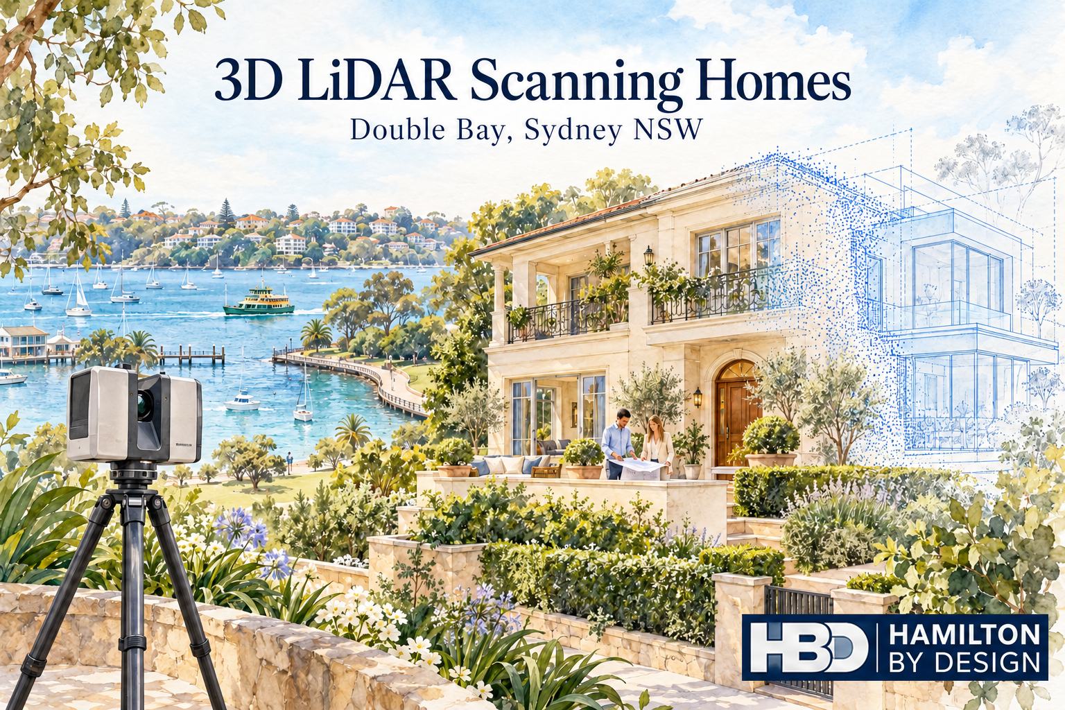


3D LiDAR Scanning Homes in Double Bay, Sydney NSW

Watercolour of a LiDAR scanner capturing a Double Bay home, with a blue point-cloud overlay, harbour views and Hamilton By Design logo.

Understand your home before planning changes

Blue outline icon of a tripod-mounted LiDAR scanner scanning a residential house.

Planning a renovation, extension or internal redesign in Double Bay? Before preparing detailed drawings, it helps to establish how your home is built today.

Original plans may be missing or may no longer reflect previous alterations. Walls, openings, floor levels and ceiling heights can differ from what appears on an old drawing.

Hamilton By Design provides 3D LiDAR scanning for homes in Double Bay, Sydney NSW, capturing visible, accessible building surfaces to create a measured digital record. This information helps architects, building designers, engineers and builders develop proposed changes around existing conditions.

Whether you are opening up a living area, replacing a staircase or extending your home, scanning provides a practical starting point for design.

What is residential 3D LiDAR scanning?

A terrestrial LiDAR scanner measures building surfaces from a series of stationary positions. Individual scans are combined into a registered point cloud, representing the geometry captured throughout the property.

Unlike a collection of separate room measurements, a coordinated point cloud allows the project team to review adjoining spaces together. This helps explain how rooms, openings and levels relate to one another.

Depending on access and the agreed scope, residential scanning can capture:

  • Internal walls, floors and ceilings.
  • Door and window openings.
  • Stairs, landings and surrounding spaces.
  • Visible beams, columns and bulkheads.
  • External faรงades and accessible roof geometry.
  • Balconies, terraces and courtyards.
  • Visible services and equipment.
  • Areas where proposed construction will connect to the existing home.

The dataset can then support selected existing-condition drawings or 3D CAD modelling where these outputs are commissioned.

Why scan a Double Bay home before renovating?

A renovation often changes how several spaces work together. Removing a wall, enlarging an opening or changing a staircase can affect adjoining rooms, circulation and the position of new fixtures.

Understanding these relationships early gives the designer more useful information when assessing options.

Replace assumptions with measured geometry

A room that appears rectangular may have walls that are slightly out of square. A ceiling may change height around a bulkhead. An opening may be positioned differently from the original plans.

These details can affect cabinetry, glazing, stairs and other components that must fit the existing building.

Scanning helps document accessible geometry so the design team can identify where closer checks are needed.

Review adjoining rooms together

For a kitchen and living room renovation, individual room dimensions may not explain the whole layout.

A registered point cloud can show the relationship between the kitchen, hallway, living area and outdoor opening. This helps the designer assess proposed layouts within the wider space.

Keep a record before demolition

Once walls, ceilings or fittings are removed, their original positions may be difficult to reconstruct.

A pre-renovation scan preserves a measured record of the surfaces captured. The project team can return to that information when reviewing an original opening, room arrangement or connection detail.

Applications for home scanning in Double Bay

Kitchen and living area alterations

Changing the kitchen layout or creating an open living area requires an understanding of existing wall positions, openings, ceiling geometry and floor levels.

Scanning can provide the spatial reference for developing the proposed layout. Structural decisions about removing walls require assessment by the appropriate engineer.

For custom cabinetry, critical installation dimensions should be checked to the tolerances required by the supplier.

House extensions

An extension must connect with the home already on site.

Scanning the adjoining rooms and relevant external surfaces helps document the geometry around floor transitions, doorways, eaves and accessible roof junctions.

This information supports the design of the connection between existing and proposed construction.

Staircase replacements

A new staircase needs to work within the available opening and connect with actual floor levels.

Capturing the stairwell, adjoining landings, nearby doors and ceiling surfaces helps the project team review the available space. Stair design, structural adequacy and compliance remain part of the relevant professional assessment.

Glazing, doors and joinery

Large windows, sliding doors and fitted joinery can depend on the relationship between several existing surfaces.

Scan data can support coordination and modelling of those interfaces. Where components require a close fit, targeted dimensional verification should form part of the agreed workflow.

Balconies and terraces

A renovation may involve changes to a balcony, terrace or the opening between indoor and outdoor areas.

Scanning accessible surfaces can help document thresholds, edges, nearby walls and level changes. Waterproofing, drainage, structural design and other specialist requirements need separate assessment.

Building services alterations

Visible pipework, ductwork and equipment can be captured where accessible. This can help coordinate proposed changes around existing services.

LiDAR does not reveal pipes, wiring or framing concealed behind walls and ceilings.

A practical example: redesigning a kitchen and terrace connection

Imagine renovating a Double Bay home to create a larger kitchen and improve access to an outdoor terrace.

The proposal includes new cabinetry, a wider glazed opening and a revised internal layout. The designer needs to understand how the kitchen floor, ceiling, adjoining walls and terrace threshold relate to one another.

A targeted scan can capture these accessible areas together before the design is finalised.

The project team can then use the point cloud and any commissioned drawings to review the layout and identify interfaces needing further investigation. Before ordering glazing or cabinetry, the relevant supplier can verify the critical dimensions.

This approach helps bring measurement questions into the design stage, when adjustments are easier to make.

From a home scan to useful project information

The right deliverable depends on who will use the data and what they need to do with it.

Some designers can work directly with point clouds. Others require selected drawings or a model of the building areas being changed.

Hamilton By Design can scope the following outputs around your project.

Registered point cloud

A coordinated dataset representing the captured surfaces, supplied in an agreed format compatible with the project teamโ€™s software.

Existing-condition drawings

Selected floor plans, elevations or sections prepared from the scan data where included in the quotation.

3D CAD models

Models of agreed building geometry to support layout review, communication and coordination.

Selected interface documentation

Drawings or modelled geometry focused on particular openings, stairs or connections relevant to the proposed work.

Scanning, drawing preparation and modelling are defined in the agreed scope. This makes clear which areas will be captured and what information will be supplied.

How we plan residential scanning

1. Understand the proposed changes

Share your property location, available plans and a description of the work. Your architect or designerโ€™s requirements help determine the capture areas and outputs.

2. Identify important interfaces

We discuss the dimensions and connections that matter most to the project, including any fabrication requirements or restricted areas.

3. Arrange access

Clear sight lines improve capture. Furniture, stored items and vegetation may obscure surfaces, so preparation is considered before the visit.

4. Capture the agreed areas

The scanner is positioned at multiple locations to collect overlapping views of accessible building surfaces.

5. Process and prepare the deliverables

The scans are registered and reviewed before the agreed point cloud, drawings or models are prepared. Relevant coverage limitations are communicated to the project team.

When should you scan your home?

For most renovation and extension projects, scanning is useful before detailed design is finalised and before demolition starts.

Capturing early allows the existing geometry to inform the proposal.

Further scanning may be appropriate after demolition exposes additional surfaces, before installing selected components or at completion. Each visit should have a defined purpose and an agreed scope.

Frequently asked questions

Can you scan an occupied home in Double Bay?

Yes, subject to suitable access arrangements. Furniture and personal items may obstruct surfaces, so we discuss the areas that need clear views before scanning.

Can I arrange scanning if I have no existing plans?

Yes. Scanning can provide measured information from which selected existing-condition drawings can be prepared. Those drawings need to be included in the agreed scope.

Do I need to scan the entire property?

Not necessarily. A focused renovation may only require the affected rooms and adjoining interfaces. A substantial extension or redesign may benefit from broader coverage.

How accurate is 3D LiDAR scanning?

Accuracy depends on the equipment, site conditions, scan positions, registration and the feature being measured.

The intended use and required tolerances should be discussed before capture. Critical fabrication dimensions may require additional verification.

Can the scanner see through walls?

No. LiDAR captures surfaces visible to the scanner. Concealed framing, wiring, pipes and other hidden features require access or a separate investigation method.

Will I automatically receive floor plans?

Floor plans, elevations, sections and models are additional outputs that must be included in the agreed scope. A point cloud is the underlying measured dataset.

Can my architect use the scan?

Yes, provided the deliverables suit their software and workflow. We confirm the required formats and outputs before work begins.

Does scanning confirm whether a wall can be removed?

No. Scanning can document visible wall positions and surrounding geometry. Determining whether a wall is load-bearing requires assessment by an appropriately qualified professional.

Does residential scanning replace a boundary survey?

No. Capturing building geometry does not establish legal property boundaries. Boundary and cadastral survey requirements should be addressed by an appropriately qualified surveyor.

How much does scanning a home in Double Bay cost?

The price depends on property size, capture areas, access, processing and the required drawings or models. Available plans, photographs and a project brief help establish an appropriate quotation.

Explore our nearby residential scanning posts:

Planning changes to your Double Bay home?

Give your project team a measured starting point before committing to detailed design.

Contact Hamilton By Design to discuss 3D LiDAR scanning for your home in Double Bay, Sydney NSW.

Send your property location, available drawings and a brief description of the proposed changes so we can define the capture areas and deliverables your project needs.


Hamilton By Design logo displayed on a blue tilted rectangle with a grey gradient background

Contact Us – Talk To Us

Name
Would you like us to arrange a phone consultation for you?
Address

Our clients:

Laser Scanning for House Extensions in Darling Point, Sydney

Oil painting of a LiDAR scanner capturing a Darling Point home, with a blue point cloud, proposed extension and Sydney Harbour in the background.

Measure your existing home before designing the extension

Blue outline icon of a tripod-mounted LiDAR scanner scanning a residential house.

A successful house extension starts with understanding the building you already have. Wall positions, floor levels, ceiling heights and roof geometry all influence how the new work connects to the existing home.

Hamilton By Design provides laser scanning for house extensions in Darling Point, Sydney, capturing accessible building surfaces to create a detailed digital record of existing conditions. This information supports architects, building designers, engineers and builders as they plan additions and coordinate construction.

Whether you are extending a living area, adding an upper level or reconfiguring the connection between indoor and outdoor spaces, scanning early can help your project team make decisions using measured information.

Why scan your home before planning an extension?

Existing drawings may be unavailable, incomplete or different from what has actually been built. Previous renovations can also introduce changes that are difficult to recognise from a floor plan alone.

A house may have walls that are slightly out of square, floors at different levels or roof lines that vary across the building. These details become particularly important where an extension joins the existing structure.

3D laser scanning captures visible surfaces as a point cloud: a digital collection of measured points representing the buildingโ€™s geometry.

Your project team can use this information to:

  • Check dimensions and spatial relationships.
  • Understand existing floor and ceiling levels.
  • Review wall alignment and opening positions.
  • Plan connections between existing and proposed spaces.
  • Develop drawings or models of the areas being altered.
  • Identify potential clashes before construction.

The greatest value often comes from capturing the home before the extension design is finalised, when adjustments are easier to make.

Focus on where the extension meets the existing home

For a Darling Point house extension, the connection between old and new deserves particular attention. A small misunderstanding at this interface can affect several parts of the design.

Floor levels and thresholds

An extension may need to connect with an existing living room, hallway, kitchen or terrace. Scanning accessible surfaces helps document level changes and the geometry around doorways and thresholds.

This gives the designer a clearer basis for planning transitions between spaces.

Walls, doors and windows

Measured wall positions and opening sizes support the layout of the extension. They also help the project team assess how proposed openings relate to adjoining rooms and external elevations.

Roof lines and ceiling heights

Roof connections can be difficult to interpret using isolated measurements. Where there is suitable visibility, laser scanning can capture external roof geometry, eaves and internal ceiling surfaces.

These measurements support design coordination, while concealed framing and inaccessible roof areas may require separate investigation.

Stairs and circulation

Adding an upper level or changing the internal layout can affect stairs, landings and access routes. A scan provides measured geometry for reviewing available space, headroom and connections between levels.

The designer and relevant consultants remain responsible for assessing the proposed arrangement against applicable requirements.

Laser scanning for Darling Point renovation and extension projects

Every home has a different combination of access, geometry and proposed changes. A targeted scan can concentrate on the rooms and external areas that matter most to the extension, while a broader scan can document more of the property for a substantial renovation.

For Darling Point projects, the scope may include:

  • Existing rooms adjoining the proposed extension.
  • External walls and accessible faรงades.
  • Courtyards, terraces and balconies.
  • Door and window openings.
  • Stairs and internal circulation areas.
  • Visible roof lines and eaves.
  • Interfaces for proposed glazing, joinery or fabricated components.

Access and visibility are reviewed when planning the work. Furniture, vegetation, reflective surfaces and neighbouring buildings can limit what can be captured, so the scanning scope should match the information your design team needs.

From laser scan to drawings and CAD models

Capturing the building is the first stage. The scan data then needs to be prepared for its intended use.

Hamilton By Design can scope deliverables around your project requirements, including:

Registered point cloud

Individual scans are aligned into a coordinated dataset representing the captured areas. The point cloud allows compatible software to display and interrogate the measured building geometry.

Existing-condition drawings

Where included in the agreed scope, scan data can support preparation of selected floor plans, elevations and sections.

These drawings give the project team a documented starting point for developing the extension.

3D CAD modelling

A model of selected building geometry can help communicate spatial relationships and coordinate the areas where proposed work meets existing construction.

The modelโ€™s coverage and level of detail are agreed before work begins.

Geometry for component coordination

Scan data can also support checking interfaces for items such as stairs, balustrades, glazing and joinery. Dimensions that are critical to fabrication should be identified early and verified using a method appropriate to the required tolerance.

Deliverables are tailored to the project. Scanning, drawings and modelling should each be clearly defined in the quotation so you know what will be supplied.

A practical process for your house extension

1. Define the proposed work

Share your property location, available drawings and a brief description of the extension. Your architectโ€™s or designerโ€™s information requirements help establish which areas need to be captured.

2. Plan access and scanning coverage

We review internal and external access, occupied areas and any features requiring particular attention. This helps establish a practical capture plan.

3. Scan the existing home

The scanner is positioned at multiple locations to capture overlapping views of accessible surfaces. Coverage is planned around the agreed project scope.

4. Process and review the data

The scans are registered and reviewed before the agreed outputs are prepared. Relevant coverage limitations are identified so the project team understands the dataset.

5. Supply the agreed deliverables

Your project team receives the point cloud and any drawings or models included in the scope, ready for use in the agreed workflow.

Reduce uncertainty before construction begins

An extension involves many decisions that depend on existing dimensions. Capturing those dimensions early can help reduce repeated site visits, clarify design assumptions and reveal geometric issues while the project is still being developed.

A shared dataset also helps the architect, engineer and builder work from consistent information.

Laser scanning cannot reveal concealed foundations, reinforcement, wall cavities or hidden services. Structural assessment, site investigation and approval work remain separate parts of the project. Its role is to provide a clearer record of the visible, accessible building geometry.

Frequently asked questions

When should I arrange laser scanning for a house extension?

Ideally, arrange scanning before detailed design begins. This gives your architect or building designer measured existing-condition information while the layout and connections are still being developed.

Scanning can also be useful during later coordination, although discovering an issue early generally leaves more options for resolving it.

Can you scan an occupied home in Darling Point?

Yes, occupied homes can be scanned, subject to suitable access. Clear views of important walls, openings and floor areas improve coverage. Any furniture movement or access arrangements can be discussed before the visit.

Can laser scanning help if I have no existing house plans?

Yes. A scan can provide measured information from which selected existing-condition drawings can be prepared. Drawing preparation needs to be included in the agreed scope.

Do I need to scan the whole house?

Not always. A smaller extension may only require the adjoining rooms, relevant external elevations and connection areas. A larger renovation may benefit from broader coverage.

The appropriate scope depends on your design teamโ€™s needs.

Can the scan capture the roof?

Visible roof surfaces and edges may be captured from suitable scanner positions. Coverage depends on sight lines, access and obstructions. Roof areas that cannot be seen require another agreed capture or measurement method.

How accurate is residential laser scanning?

The accuracy of the delivered dataset depends on the equipment, scanning conditions, coverage, registration and verification process. We discuss the intended use and required tolerances when defining the scope.

Critical dimensions for fabrication or close-fitting connections may need additional checks.

Will my architect be able to use the scan data?

Point clouds can be used in compatible design software. Before scanning, we confirm the required file format and whether your architect needs a point cloud, drawings, a model or a combination of outputs.

Does a laser scan replace a boundary survey?

No. A building scan records captured geometry. Property boundaries, cadastral information and any required survey certification should be addressed by an appropriately qualified surveyor.

Can scanning guarantee that the extension will fit?

Scanning provides measured information to support design and coordination. Fit also depends on how that information is interpreted, the design tolerances, fabrication and construction. Critical interfaces should be checked as part of the projectโ€™s verification process.

How much does laser scanning for a house extension cost?

Pricing depends on the areas to be captured, access, site time, processing and the required deliverables. Providing available plans, photographs and a description of the proposed work helps us prepare a quotation suited to your project.

Planning a house extension in Darling Point?

Start with measured information about your existing home.

Contact Hamilton By Design to discuss laser scanning for your Darling Point house extension. Send your property location, available drawings and a brief description of the proposed changes so we can scope the capture and deliverables around your project.

Capture the existing home. Give your design team a clearer starting point.

Laser Scanning for House Extensions in Darling Point, Sydney

Laser Scanning for House Extensions in Darling Point, Sydney

Measure your existing home before designing the extension

A successful house extension starts with understanding the building you already have. Wall positions, floor levels, ceiling heights and roof geometry all influence how the new work connects to the existing home.

Hamilton By Design provides laser scanning for house extensions in Darling Point, Sydney, capturing accessible building surfaces to create a detailed digital record of existing conditions. This information supports architects, building designers, engineers and builders as they plan additions and coordinate construction.

Whether you are extending a living area, adding an upper level or reconfiguring the connection between indoor and outdoor spaces, scanning early can help your project team make decisions using measured information.

Why scan your home before planning an extension?

Existing drawings may be unavailable, incomplete or different from what has actually been built. Previous renovations can also introduce changes that are difficult to recognise from a floor plan alone.

A house may have walls that are slightly out of square, floors at different levels or roof lines that vary across the building. These details become particularly important where an extension joins the existing structure.

3D laser scanning captures visible surfaces as a point cloud: a digital collection of measured points representing the buildingโ€™s geometry.

Your project team can use this information to:

  • Check dimensions and spatial relationships.
  • Understand existing floor and ceiling levels.
  • Review wall alignment and opening positions.
  • Plan connections between existing and proposed spaces.
  • Develop drawings or models of the areas being altered.
  • Identify potential clashes before construction.

The greatest value often comes from capturing the home before the extension design is finalised, when adjustments are easier to make.

Focus on where the extension meets the existing home

For a Darling Point house extension, the connection between old and new deserves particular attention. A small misunderstanding at this interface can affect several parts of the design.

Floor levels and thresholds

An extension may need to connect with an existing living room, hallway, kitchen or terrace. Scanning accessible surfaces helps document level changes and the geometry around doorways and thresholds.

This gives the designer a clearer basis for planning transitions between spaces.

Walls, doors and windows

Measured wall positions and opening sizes support the layout of the extension. They also help the project team assess how proposed openings relate to adjoining rooms and external elevations.

Roof lines and ceiling heights

Roof connections can be difficult to interpret using isolated measurements. Where there is suitable visibility, laser scanning can capture external roof geometry, eaves and internal ceiling surfaces.

These measurements support design coordination, while concealed framing and inaccessible roof areas may require separate investigation.

Stairs and circulation

Adding an upper level or changing the internal layout can affect stairs, landings and access routes. A scan provides measured geometry for reviewing available space, headroom and connections between levels.

The designer and relevant consultants remain responsible for assessing the proposed arrangement against applicable requirements.

Laser scanning for Darling Point renovation and extension projects

Every home has a different combination of access, geometry and proposed changes. A targeted scan can concentrate on the rooms and external areas that matter most to the extension, while a broader scan can document more of the property for a substantial renovation.

For Darling Point projects, the scope may include:

  • Existing rooms adjoining the proposed extension.
  • External walls and accessible faรงades.
  • Courtyards, terraces and balconies.
  • Door and window openings.
  • Stairs and internal circulation areas.
  • Visible roof lines and eaves.
  • Interfaces for proposed glazing, joinery or fabricated components.

Access and visibility are reviewed when planning the work. Furniture, vegetation, reflective surfaces and neighbouring buildings can limit what can be captured, so the scanning scope should match the information your design team needs.

From laser scan to drawings and CAD models

Capturing the building is the first stage. The scan data then needs to be prepared for its intended use.

Hamilton By Design can scope deliverables around your project requirements, including:

Registered point cloud

Individual scans are aligned into a coordinated dataset representing the captured areas. The point cloud allows compatible software to display and interrogate the measured building geometry.

Existing-condition drawings

Where included in the agreed scope, scan data can support preparation of selected floor plans, elevations and sections.

These drawings give the project team a documented starting point for developing the extension.

3D CAD modelling

A model of selected building geometry can help communicate spatial relationships and coordinate the areas where proposed work meets existing construction.

The modelโ€™s coverage and level of detail are agreed before work begins.

Geometry for component coordination

Scan data can also support checking interfaces for items such as stairs, balustrades, glazing and joinery. Dimensions that are critical to fabrication should be identified early and verified using a method appropriate to the required tolerance.

Deliverables are tailored to the project. Scanning, drawings and modelling should each be clearly defined in the quotation so you know what will be supplied.

A practical process for your house extension

1. Define the proposed work

Share your property location, available drawings and a brief description of the extension. Your architectโ€™s or designerโ€™s information requirements help establish which areas need to be captured.

2. Plan access and scanning coverage

We review internal and external access, occupied areas and any features requiring particular attention. This helps establish a practical capture plan.

3. Scan the existing home

The scanner is positioned at multiple locations to capture overlapping views of accessible surfaces. Coverage is planned around the agreed project scope.

4. Process and review the data

The scans are registered and reviewed before the agreed outputs are prepared. Relevant coverage limitations are identified so the project team understands the dataset.

5. Supply the agreed deliverables

Your project team receives the point cloud and any drawings or models included in the scope, ready for use in the agreed workflow.

Reduce uncertainty before construction begins

An extension involves many decisions that depend on existing dimensions. Capturing those dimensions early can help reduce repeated site visits, clarify design assumptions and reveal geometric issues while the project is still being developed.

A shared dataset also helps the architect, engineer and builder work from consistent information.

Laser scanning cannot reveal concealed foundations, reinforcement, wall cavities or hidden services. Structural assessment, site investigation and approval work remain separate parts of the project. Its role is to provide a clearer record of the visible, accessible building geometry.

Frequently asked questions

When should I arrange laser scanning for a house extension?

Ideally, arrange scanning before detailed design begins. This gives your architect or building designer measured existing-condition information while the layout and connections are still being developed.

Scanning can also be useful during later coordination, although discovering an issue early generally leaves more options for resolving it.

Can you scan an occupied home in Darling Point?

Yes, occupied homes can be scanned, subject to suitable access. Clear views of important walls, openings and floor areas improve coverage. Any furniture movement or access arrangements can be discussed before the visit.

Can laser scanning help if I have no existing house plans?

Yes. A scan can provide measured information from which selected existing-condition drawings can be prepared. Drawing preparation needs to be included in the agreed scope.

Do I need to scan the whole house?

Not always. A smaller extension may only require the adjoining rooms, relevant external elevations and connection areas. A larger renovation may benefit from broader coverage.

The appropriate scope depends on your design teamโ€™s needs.

Can the scan capture the roof?

Visible roof surfaces and edges may be captured from suitable scanner positions. Coverage depends on sight lines, access and obstructions. Roof areas that cannot be seen require another agreed capture or measurement method.

How accurate is residential laser scanning?

The accuracy of the delivered dataset depends on the equipment, scanning conditions, coverage, registration and verification process. We discuss the intended use and required tolerances when defining the scope.

Critical dimensions for fabrication or close-fitting connections may need additional checks.

Will my architect be able to use the scan data?

Point clouds can be used in compatible design software. Before scanning, we confirm the required file format and whether your architect needs a point cloud, drawings, a model or a combination of outputs.

Does a laser scan replace a boundary survey?

No. A building scan records captured geometry. Property boundaries, cadastral information and any required survey certification should be addressed by an appropriately qualified surveyor.

Can scanning guarantee that the extension will fit?

Scanning provides measured information to support design and coordination. Fit also depends on how that information is interpreted, the design tolerances, fabrication and construction. Critical interfaces should be checked as part of the projectโ€™s verification process.

How much does laser scanning for a house extension cost?

Pricing depends on the areas to be captured, access, site time, processing and the required deliverables. Providing available plans, photographs and a description of the proposed work helps us prepare a quotation suited to your project.

Planning a house extension in Darling Point?

Start with measured information about your existing home.

Contact Hamilton By Design to discuss laser scanning for your Darling Point house extension. Send your property location, available drawings and a brief description of the proposed changes so we can scope the capture and deliverables around your project.

Capture the existing home. Give your design team a clearer starting point.


Hamilton By Design logo displayed on a blue tilted rectangle with a grey gradient background

Contact Us – Talk To Us

Name
Would you like us to arrange a phone consultation for you?
Address

Our clients:


Chute Design Limeira, Sรฃo Paulo โ€” Consistent Material Flow and Reduced Wear

Hamilton By Design illustration of LiDAR scanning and a cutaway mineral processing chute, showing ore flow and wear liners for chute design in Limeira, Sรฃo Paulo.

Consistent material flow, reduced wear and practical maintenance

Blue line icon of a tripod-mounted LiDAR scanner surveying a mineral processing plant with a hopper, conveyors and transfer chute.

Transfer chutes connect critical stages of a mineral processing plant. From crusher discharge to screen feed and conveyor transfers, their design influences how reliably material moves through the operation.

Poorly matched chute geometry can contribute to blockages, spillage, uneven equipment loading and premature liner wear. These problems can increase maintenance demands and interrupt production.

Hamilton By Design offers mechanical design support for mineral processing equipment manufacturers, mining suppliers, fabrication workshops and plant operators in Limeira, Sรฃo Paulo, and businesses serving mining projects throughout Brazil.

Drawing on Australian mining and materials handling experience, we develop chute designs that bring together material flow, wear protection, equipment interfaces and fabrication requirements.

Planning a new transfer chute or upgrading an existing installation? Discuss your project with Hamilton By Design.

Chute design for mineral processing applications

Each transfer point has a specific purpose within the processing circuit. A chute feeding a screen requires a different approach from one receiving coarse material discharged by a crusher.

Our design support can cover:

  • Conveyor-to-conveyor transfer chutes.
  • Crusher feed and discharge chutes.
  • Screen feed, discharge and product collection chutes.
  • Transfer arrangements for ore, crushed rock and mineral products.
  • Chute modifications associated with plant upgrades.
  • Replacement chute bodies and wear liner systems.

We consider how the chute receives material, controls its path and delivers it to the next item of equipment.

The objective is reliable transfer across the agreed operating range, with a design that fits the plant and supports practical maintenance.

Understand the material before developing the geometry

Mineral processing chutes must accommodate the characteristics of the material passing through them.

Coarse particles, abrasive rock, wet fines and variable feed conditions can create different flow and wear challenges. Understanding these conditions helps establish suitable chute geometry and wear protection.

Our design process considers:

  • Material type, bulk density and particle size distribution.
  • Maximum lump size and the proportion of fines.
  • Moisture content and potential for adhesion or build-up.
  • Normal, peak and variable throughput.
  • Conveyor speed and material discharge trajectory.
  • Transfer height and changes in flow direction.
  • Receiving belt, crusher or screen requirements.
  • Existing blockages, wear patterns and maintenance records.

Where necessary, material testing or additional operating data can be included in the scope to resolve uncertainties before detailed design.

Control the flow and reduce concentrated wear

Wear protection begins with understanding how material moves through the chute.

Impact at entry points, abrupt changes in direction and concentrated sliding contact can place heavy demands on chute surfaces. We review these areas alongside the liner arrangement.

Depending on the application, the design may incorporate:

  • Geometry that guides the material through the transfer.
  • Replaceable liners selected for the expected abrasion and impact.
  • Localised protection at high-wear areas.
  • Material-retaining features where suitable for the feed conditions.
  • Modular liner sections for practical replacement.

Wear-resistant steel, rubber, polyurethane and ceramic systems each have different application requirements. Selection should reflect the material, impact conditions, attachment method and maintenance strategy.

Our aim is to reduce avoidable wear and improve serviceability. Expected liner life depends on the operating conditions and selected system.

Assess proposed designs with particle-flow simulation

For complex transfers or recurring flow problems, Discrete Element Methodโ€”DEMโ€”analysis can be included in the project scope.

DEM can help assess material trajectories, accumulation, discharge behaviour and interaction with chute surfaces. It can also support comparison of alternative geometries before fabrication.

Representative material properties and appropriate calibration are essential to obtaining useful results. Simulation findings should be assessed alongside site observations, engineering judgement and operating data.

From existing plant to fabrication-ready documentation

Plant upgrades often require new equipment to fit within existing steelwork, conveyors and restricted installation spaces.

Hamilton By Design can work from drawings, photographs, verified measurements and suitable point cloud data to develop the chute and its interfaces.

Where 3D scanning is required, capture arrangements and responsibilities can be agreed as part of the scope.

Deliverables can include:

  • Existing equipment and interface models.
  • Concept designs and option reviews.
  • Detailed 3D chute models.
  • General arrangement drawings.
  • Fabrication drawings and component details.
  • Wear liner layouts and replacement details.
  • Coordination with client engineers and fabrication teams.

The agreed documentation supports manufacture, installation and future maintenance.

Design for inspection and liner replacement

A chute should be accessible to the people responsible for keeping it operational.

We consider inspection openings, liner handling, fastener access, lifting provisions and installation clearances. Where applicable, the scope can also address guarding and isolation interfaces with surrounding equipment.

Maintenance requirements should be established early so that access and replacement tasks are considered alongside material flow.

For Brazilian projects, applicable local requirements and approval responsibilities are agreed with the client and their local engineering team.

Australian mining experience, working with Limeiraโ€™s industry

Hamilton By Design welcomes opportunities to collaborate with equipment manufacturers, engineering teams and fabrication businesses in Limeira.

We bring Australian mining and materials handling experience, supported by mechanical design, 3D modelling and scan-to-CAD capabilities. Local partners bring knowledge of their equipment, operating conditions and manufacturing requirements.

Our Portuguese is still a work in progress, so we place particular importance on clear drawings, agreed terminology and documented design reviews.

And we already appreciate a good Brazilian start to the morning: pรฃo de queijo and cafรฉ.

Frequently asked questions

Can you redesign a chute that repeatedly blocks?

Yes. We can assess the existing geometry, material characteristics and operating conditions to develop improvement options. Details of when blockages occurโ€”including changes in moisture or throughputโ€”help identify the likely causes.

Can you design chutes for abrasive ore and crushed rock?

Yes. The scope can address chute geometry, impact zones, liner selection and replacement arrangements. Material characteristics and operating data are needed to develop a suitable design.

Can you use an existing plant scan?

Yes. Suitable point cloud data can help establish equipment interfaces and available space. Critical dimensions and areas obscured during scanning may require additional verification.

Can you guarantee a specific liner life?

A liner-life commitment requires supporting evidence about the material, throughput and operating conditions. We can develop a wear strategy and document the design assumptions for comparison with operating performance.

Can you work remotely with a manufacturer in Limeira?

Yes. Remote design support can be arranged using agreed drawings, measurements, scan data and review meetings. Site verification, fabrication responsibilities and local approvals are defined within the project scope.

Discuss your mineral processing chute project

Send Hamilton By Design your existing drawings, photographs, material details, throughput requirements and a description of the transfer problem.

Whether you are developing new mineral processing equipment or upgrading a mining installation, we can help establish a practical design scope.

Contact Hamilton By Design to discuss chute design for mineral processing and mining projects in Limeira, Sรฃo Paulo.


Hamilton By Design logo displayed on a blue tilted rectangle with a grey gradient background

Contact Us – Talk To Us

Name
Would you like us to arrange a phone consultation for you?
Address

Our clients: