Learning From Mining Industry Incidents | Engineering Insight
Why Engineers Study Failures Without Assigning Blame
In engineering, learning does not come only from success.
Some of the most valuable improvements in safety, reliability, and design practice come from studying incidents after they occur — not to assign blame, but to better understand how systems behave under real-world conditions.
At Hamilton By Design, our interest in industry incidents is purely educational.
We do not provide legal opinions, and we do not involve ourselves in litigation.
Our focus is engineering learning and risk reduction.
Why Engineers Study Incidents
Engineering is a discipline built on:
- Understanding failure modes
- Learning from unintended outcomes
- Improving designs so similar events are less likely to occur again
Courts determine liability.
Engineers determine how systems can be made safer.
These are very different roles.

An Example From the Mining Fabrication Sector
A recent court-reported incident in the Australian mining fabrication sector involved a serious worker injury during the handling of a large steel plate.
This event has been widely reported in industry safety communications and regulator summaries.
The matter has been dealt with by the courts.
Our interest is not who was responsible — but what can be learned from an engineering and design perspective.
Separating Legal Outcomes From Engineering Lessons
When incidents are discussed publicly, it is easy for conversations to drift toward:
- Fault
- Error
- Individual actions
- Compliance outcomes
From an engineering standpoint, a more useful question is:
“Why was this failure mode possible in the first place?”
This shifts the focus from people to systems.
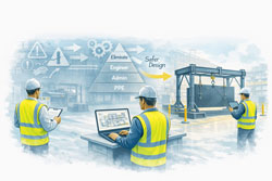
The Engineering Perspective: Systems, Not Individuals
In fabrication, mining, and heavy industry environments, engineers routinely work with:
- Large masses
- Stored energy
- Gravity-driven hazards
- Tight workspaces
- Time pressure
In these environments, safe outcomes should not rely on:
- Perfect timing
- Continuous vigilance
- People always being in the right place
Good engineering design assumes:
- Humans make mistakes
- Conditions change
- Equipment can fail
- Distractions occur
And it designs accordingly.
Learning Through the Hierarchy of Controls
One of the most useful tools engineers have for learning from incidents is the hierarchy of controls.
From a learning perspective, incidents often highlight opportunities to move risk higher up the hierarchy:
- Can the hazard be eliminated?
- Can the task be re-designed so people are not exposed?
- Can engineering controls prevent a single failure from becoming an injury?
- Are procedures being used where physical controls could exist instead?
These are design questions, not legal ones.
Why This Matters for Engineering Practice
Studying incidents like this helps engineers:
- Identify hidden assumptions in workshop layouts
- Improve material handling design
- Reduce reliance on administrative controls
- Design processes that are more tolerant of variation
- Prevent “normalised” risk from becoming invisible
Importantly, these lessons apply well beyond a single incident or company.
The Link to Broader Engineering Failures
The same learning approach is used when engineers study:
- Structural failures
- Mining incidents
- Equipment damage
- Tailings dam collapses
- Process plant upsets
In each case, the goal is the same:
Understand how design decisions influence risk over time.
Not to judge — but to improve.
Our Position at Hamilton By Design
To be clear:
- We do not comment on legal responsibility
- We do not provide expert opinions on prosecutions
- We do not participate in legal proceedings
Our interest is strictly:
- Engineering learning
- Design improvement
- Risk reduction
- Better outcomes for industry
We believe that open, professional learning from incidents strengthens engineering practice and improves safety across the sector.
Final Thought
Engineering advances when professionals are willing to say:
“What can we learn from this?”
Without blame.
Without legal positioning.
Without hindsight judgement.
Just better design, informed by real-world experience.
📩 Engineering-Led Design Matters
If you’re working in mining, fabrication, or heavy industry and want to reduce risk through better design decisions, Hamilton By Design supports engineering-led thinking that prioritises:
- Hazard elimination
- Fit-first-time outcomes
- Design-for-fabrication
- Systems that don’t rely on perfect behaviour


Talk to an engineer early.