Engineering Integrity, Failure Evolution, and Energy Transition: A Mechanical Engineerโ€™s Perspective on Australiaโ€™s Ageing Coal Fleet

This paper examines the mechanical degradation, failure mechanisms, and system-level reliability implications of Australiaโ€™s ageing coal-fired power generation assets, focusing on Callide Power Station (Queensland) and Yallourn Power Station (Victoria). Both stations have experienced significant mechanical failures in the past five years, exposing vulnerabilities in maintenance, asset management, and risk governance under conditions of declining reinvestment.
From a mechanical engineering standpoint, these failures illustrate the predictable end-of-life behaviour of large rotating and pressure-bound systems when maintenance expenditure, material renewal, and operational monitoring decline. The paper argues that sustained industrial reliabilityโ€”and thus national energy and employment securityโ€”requires engineering-informed policy that balances decarbonisation with technical integrity management.


Coal-fired power stations are among the most complex mechanical systems ever built in Australia. They integrate high-temperature, high-pressure thermodynamic processes with massive rotating equipment, lubrication systems, and precision alignment tolerances.

From a mechanical engineerโ€™s perspective, their reliability depends on three interlinked pillars:

  1. Structural and material integrity,
  2. Lubrication and vibration control, and
  3. Predictive maintenance and monitoring.

However, as the nation accelerates toward renewable transition targets, investment in these legacy systems has declined. Mechanical failures at Callide and Yallourn are therefore not random accidents but the mechanical manifestation of economic and policy choices.

This analysis seeks to understand those failures in engineering terms, predict future risks, and outline how a re-commitment to industrial infrastructure and jobs requires a concurrent commitment to mechanical reliability.


Technical Overview of Recent Failures

Callide Power Station

Callideโ€™s units span several generations of design and material technology. The C4 explosion (2021) was catastrophic: the failure originated within the turbine hall, leading to structural collapse and large-scale ejection of debris.
Subsequent analysis by CS Energy and external investigators identified battery charger replacement errors, inadequate isolation protocols, and loss of process safety discipline as initiators.

From an engineering integrity perspective, the incident represents a compound failure:

  • Mechanical systems operated under degraded conditions;
  • Electrical and process-control systems failed to detect early anomalies;
  • Organisational maintenance controls were insufficient to interrupt escalation.

Later failures โ€” including the C3 boiler pressure event (2025) and cooling tower collapse (2022) โ€” further confirm that structural materials, corrosion protection, and load-carrying assemblies had entered the fatigueโ€“creep interaction phase of their service life.

Yallourn Power Station

At Yallourn, the August 2025 low-pressure turbine dislodgement occurred after decades of vibration monitoring alarms and bearing wear signals. Earlier (2024) shutdowns for โ€œhigh vibration alarmsโ€ indicated growing rotor dynamic instability.
When the Unit 2 turbine dislodged, the damage pattern suggested bearing wear, misalignment, or bolt relaxation leading to component displacement.

In mechanical engineering terms, this is a classic late-life failure sequence:

  1. Fatigue crack initiation in critical load-carrying components (rotor or coupling bolts),
  2. Progressive loosening and unbalance,
  3. Dynamic amplification under operating RPM,
  4. Catastrophic structural displacement.

The turbineโ€™s dislodgement was therefore an expected end-of-life event, accelerated by reduced overhaul investment and ageing metallurgical properties.


Comparative Engineering Analysis

Engineering DimensionCallideYallournComparison / Insight
Failure TypeExplosion / Pressure Containment BreachTurbine Mechanical DislodgementCallide shows energy-release failure; Yallourn a structural integrity loss.
Root Mechanical CauseOverpressure / process safetyFatigue, unbalance, bearing or bolt failureBoth reflect cumulative degradation.
Indicative Material StateCreep-fatigued pressure shells; corroded supportsThermal-fatigued steel, worn journalsMetallurgical ageing dominates both.
Maintenance CultureProcess-safety erosionReactive, โ€œrun-to-retirementโ€Organisational degradation common factor.
System OutcomeExplosion and total destructionSevere mechanical damage, unit outageBoth reduce grid reliability and reveal systemic neglect.

These failures share a unifying pattern recognised in mechanical reliability theory:

Late-life degradation compounded by maintenance deferral and organisational fatigue produces cascading mechanical failure modes that were once preventable.


Predicting Future Failure Behaviour

Mechanical engineers use reliability-centred maintenance (RCM) models to quantify end-of-life risk.
For rotating equipment, mean time to failure (MTTF) typically decreases exponentially once fatigue propagation exceeds ~70 % of material endurance life.

Data from the National Electricity Market (NEM) indicates:

  • Forced outage frequency has doubled since 2012.
  • Vibration and lubrication alarms are rising in frequency.
  • Unit unavailability correlates strongly (Rยฒ > 0.8) with turbine age and last major overhaul date.

Projected forward, these indicators imply that without major overhauls or component replacements, most Australian coal units will face critical mechanical reliability decline by 2032โ€“2035.


Engineering Economics and Policy Interaction

From an engineering management perspective, the problem is not purely technical โ€” it is thermo-economic.

  • A major turbine retrofit (~A$25โ€“40 million per unit) is uneconomic for plants scheduled for closure in under a decade.
  • Operators thus defer maintenance, accepting rising mechanical risk.
  • The probability of catastrophic failure increases sharply as the cost of prevention declines below the cost of repair.

This is the engineering expression of policy-induced obsolescence: political commitments to retire coal reduce the incentive to sustain its mechanical integrity, even while industries still depend on its output.


Industrial Reliability and the Employment Interface

Reliable baseload power is the foundation for industrial continuity.
From the standpoint of a mechanical engineer, industrial productivity is a function of mechanical uptime: Productivity=f(Power Reliability,Maintenance Efficiency)\text{Productivity} = f(\text{Power Reliability}, \text{Maintenance Efficiency})Productivity=f(Power Reliability,Maintenance Efficiency)

When power generation becomes intermittentโ€”whether from renewable intermittency or coal unreliabilityโ€”industrial operations must compensate with redundancy, backup generation, or load-shedding. These add capital and operational costs that ultimately affect employment.

Regional Implications

  • Queensland retains a stronger firm power horizon (coal + gas + hydro until ~2035), giving industry more operational certainty.
  • Victoria, by contrast, will face a reliability inflection point after Yallourn (2028) and Loy Yang A (2035) closures.

Without firm generation or large-scale storage online, manufacturing regions risk power volatilityโ€”directly translating to production downtime and job insecurity.


Engineering the Transition: Commitment to Jobs and Infrastructure

From a mechanical engineering ethics and systems standpoint, a commitment to industry must be synonymous with a commitment to mechanical reliability.
That requires three converging actions:

Asset Integrity Management:
Continuous structural health monitoring, vibration analysis, and overhaul planning for remaining thermal units.
Even in decline, they must be safely and predictably retired.

Design and Commissioning of Replacement Systems:
Engineers must ensure that renewable generation, storage, and transmission assets meet equivalent reliability and maintainability standards.
This includes redundancy design, grid inertia replacement, and mechanical resilience of large rotating machinery (e.g., pumped hydro, turbines, bearings).

Workforce Transition as Engineering Continuity:
The skills used to maintain turbines, bearings, and boilers are transferable to wind, hydro, and hydrogen equipment.
Protecting those jobs preserves both mechanical capability and national energy security.


Engineering Conclusions

From a mechanical engineerโ€™s viewpoint, the failures at Callide and Yallourn are textbook case studies of end-of-life degradation under policy-driven neglect.
They illustrate that:

  1. Mechanical degradation is predictable โ€” vibration, lubrication, and thermal-stress indicators were present years before failure.
  2. Organisational and policy decisions override engineering recommendations โ€” maintenance deferral was economic, not technical.
  3. Systemic reliability cannot be sustained without mechanical investment โ€” whether in turbines, batteries, or hydro equipment, engineering integrity remains central.
  4. A national commitment to industry equals a commitment to engineering.

If Australia seeks to safeguard its industrial base and employment, it must invest not only in new energy technologies but in the mechanical soundness of the systems that bridge the transition.
Neglecting this will reproduce the same failure patternsโ€”just in new forms of infrastructure.


References (Indicative)

  • CS Energy (2024). Callide C4 Incident Investigation Summary.
  • WattClarity (2025). Analysis of Yallourn Unit 2 Trip and Frequency Response.
  • AEMO (2025). Generator Reliability Performance Report.
  • EnergyAustralia (2025). Yallourn Mechanical Maintenance Overview.
  • IEEFA (2025). Delaying Coal Power Exits: Engineering and Economic Implications.
  • ASME (2023). Guidelines on Turbine Rotor Life Assessment and Remaining Life Prediction.

3D LiDAR scanning and 3D modelling service button โ€” laser scanner capturing a point cloud for engineering and CAD modelling
Mechanical engineering services


Finite Element Analysis (FEA) engineering simulation button
Mechanical engineering services


3D CAD Modelling Australia service banner for Hamilton By Design


CHPP Engineering title graphic featuring bold white text reading "CHPP Engineering" centred on a blue rounded rectangle background.
Pipework Drafting title graphic featuring bold white text reading "Pipework Drafting" centred on a blue rounded rectangle background.
3D LiDAR Scanning for Engineering Projects title graphic featuring bold white text on a blue rounded rectangle background.


Finite Element Analysis (FEA) engineering simulation button
Structural drafting services button
Mechanical drafting services button


Australian Drafting logo featuring bold white text reading "Australian Drafting" centred on a blue rounded rectangle background.
Engineering Governance title graphic featuring bold white text reading "Engineering Governance" centred on a blue rounded rectangle background.
Engineering-Grade LiDAR Scanning title graphic featuring bold white text on a blue rounded rectangle background.

Chute Design in the Mining Industry

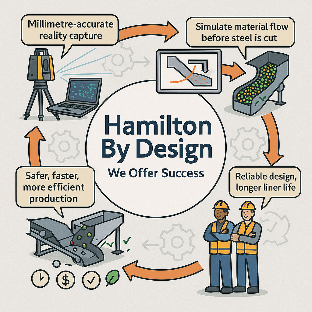
Infographic showing Hamilton By Designโ€™s engineering workflow, including millimetre-accurate LiDAR reality capture, material-flow simulation, optimised chute designs, and safer, more efficient production outcomes. Two workers in PPE highlight reliable design and longer liner life, with icons representing time, cost and quality benefits.

Getting Coal, Hard Rock, and ROM Material Flow Right

Chute design is one of the most critical yet challenging aspects of mining and mineral processing. Whether you are handling coal, hard rock ore, or raw ROM material, chutes and transfer stations are the unsung workhorses of every operation. When designed well, they guide material smoothly, minimise wear, and keep conveyors running. When designed poorly, they cause blockages, spillage, excessive dust, and expensive downtime.

Modern chute design has moved far beyond rules of thumb and back-of-the-envelope sketches. Today, successful projects rely on accurate as-built data, particle trajectory analysis, and advanced Discrete Element Method (DEM) simulation to predict, visualise, and optimise material flow before steel is cut. In this article, we explore why these tools have become essential, how they work together, and where software can โ€” and cannot โ€” replace engineering judgement.


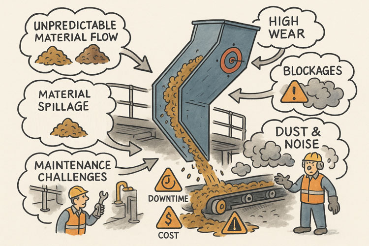
Illustration showing common problems with poorly designed material-handling chutes. A chute discharges material onto a conveyor while issues are highlighted around it: unpredictable material flow, material spillage, maintenance challenges, high wear, blockages, and dust and noise. Warning icons for downtime and cost appear on the conveyor, and workers are shown dealing with the resulting hazards and maintenance tasks.

The Challenge of Chute Design

Coal and hard rock have very different flow behaviours. Coal tends to be softer, generate more dust, and be prone to degradation, while hard rock is more abrasive and can damage chutes if impact angles are not controlled. ROM material adds another level of complexity โ€” oversize lumps, fines, and moisture variation can cause hang-ups or uneven flow.

Chute design must balance several competing objectives:

  • Control the trajectory of incoming material to reduce impact and wear
  • Prevent blockages by maintaining flowability, even with wet or sticky ore
  • Manage dust and noise to meet environmental and workplace health requirements
  • Fit within existing plant space with minimal modification to conveyors and structures
  • Be maintainable โ€” liners must be accessible and replaceable without excessive downtime

Meeting all these goals without accurate data and simulation is like trying to design in the dark.


Illustrated graphic showing a tripod-mounted 3D laser scanner capturing millimetre-accurate as-built data in an industrial plant with conveyors and walkways. Speech bubbles highlight issues such as โ€œOutdated drawings donโ€™t tell the full storyโ€ and โ€œModifications rarely get documented.โ€ The scan data is shown being visualised on a laptop, with notes describing full coverage of conveyors, walkways, and services. Benefits listed along the bottom include faster data collection, fewer site revisits, safer shutdowns, accurate starting point for design simulation, and safer outcomes that ensure designs fit first time.

Capturing the Truth with 3D Scanning

The first step in any successful chute project is to understand the as-built environment. In many operations, drawings are outdated, modifications have been made over the years, and the real plant geometry may differ from what is on paper. Manual measurement is slow, risky, and often incomplete.

This is where 3D laser scanning changes the game. Using tripod-mounted or mobile LiDAR scanners, engineers can capture the entire transfer station, conveyors, surrounding steelwork, and services in a matter of hours. The result is a dense point cloud with millimetre accuracy that reflects the true state of the plant.

From here, the point cloud is cleaned and converted into a 3D model. This ensures the new chute design will not clash with existing structures, and that all clearances are known. It also allows maintenance teams to plan safe access for liner change-outs and other work, as the scanned model can be navigated virtually to check reach and access envelopes.


Understanding Particle Trajectory

Once the physical environment is known, the next challenge is to understand the particle trajectory โ€” the path that material takes as it leaves the head pulley or previous transfer point.

Trajectory depends on belt speed, material characteristics, and discharge angle. For coal, fine particles may spread wider than the coarse fraction, while for ROM ore, large lumps may follow a ballistic path that needs to be controlled to prevent impact damage.

Accurately modelling trajectory ensures that the material enters the chute in the right location and direction. This minimises impact forces, reducing wear on liners and avoiding the โ€œsplashโ€ that creates spillage and dust. It also prevents the material from hitting obstructions or dead zones that could lead to build-up and blockages.
Modern software can plot the trajectory curve for different loading conditions, providing a starting point for chute geometry. This is a critical step โ€” if the trajectory is wrong, the chute design will be fighting against the natural path of the material.


The Power of DEM Simulation

While trajectory gives a first approximation, real-world flow is far more complex. This is where Discrete Element Method (DEM) simulation comes into play. DEM models represent bulk material as thousands (or millions) of individual particles, each following the laws of motion and interacting with one another.

When a DEM simulation is run on a chute design:

  • You can visualise material flow in 3D, watching how particles accelerate, collide, and settle
  • Impact zones become clear, showing where liners will wear fastest
  • Areas of turbulence, dust generation, or segregation are identified
  • Build-up points and potential blockages are predicted

This allows engineers to experiment with chute geometry before fabrication. Angles can be changed, ledges removed, and flow-aiding features like hood and spoon profiles or rock-boxes optimised to achieve smooth, controlled flow.

For coal, DEM can help ensure material lands gently on the receiving belt, reducing degradation and dust. For hard rock, it can ensure that the energy of impact is directed onto replaceable wear liners rather than structural plate. For ROM ore, it can help prevent oversize lumps from wedging in critical locations.


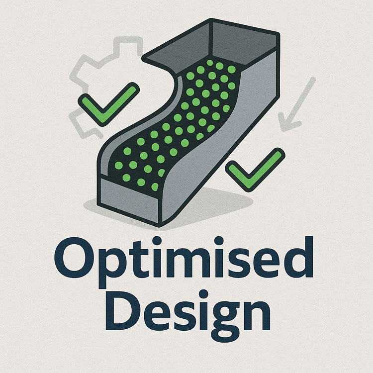
Illustration of an optimised chute design showing material flow represented by green particles, with check marks and gear icons indicating improved efficiency and engineered performance.

๐Ÿ–ฅ Strengths and Limitations of Software

Modern DEM packages are powerful, but they are not magic. Software such as EDEM, Rocky DEM, or Altairโ€™s tools can simulate a wide range of materials and geometries, but they rely on good input data and skilled interpretation.

Key strengths include:

  • Ability to model complex, 3D geometries and particle interactions
  • High visualisation power for communicating designs to stakeholders
  • Capability to run multiple scenarios (different feed rates, moisture contents, ore types) quickly

However, there are limitations:

  • Material calibration is critical. If the particle shape, friction, and cohesion parameters are wrong, the results will not match reality.
  • Computational cost can be high โ€” detailed simulations of large chutes with millions of particles may take hours or days to run.
  • Engineering judgement is still needed. Software will not tell you the โ€œbestโ€ design โ€” it will only show how a proposed design behaves under given conditions.

Thatโ€™s why DEM is best used as part of a holistic workflow that includes field data, trajectory analysis, and experienced design review.


From Model to Real-World Results

When the simulation results are validated and optimised, the design can be finalised. The point cloud model ensures the chute will fit in the available space, and the DEM results give confidence that it will perform as intended.

This means fabrication can proceed with fewer changes and less risk. During shutdown, installation goes smoothly, because clashes have already been resolved in the digital model. Once commissioned, the chute delivers predictable flow, less spillage, and longer liner life.


Why It Matters More Than Ever

Todayโ€™s mining operations face tighter production schedules, stricter environmental compliance, and increasing cost pressures. Downtime is expensive, and the margin for error is shrinking.

By combining 3D scanning, trajectory modelling, and DEM simulation, operations can move from reactive problem-solving to proactive improvement. Instead of waiting for blockages or failures, they can design out the problems before they occur, saving both time and money.


Partnering for Success

At Hamilton by Design, we specialise in turning raw site data into actionable insights. Our team uses advanced 3D scanning to capture your transfer stations with precision, builds accurate point clouds and CAD models, and runs calibrated DEM simulations to ensure your new chute design performs from day one.

Whether youโ€™re working with coal, hard rock, or ROM ore, we help you deliver designs that fit first time, reduce maintenance headaches, and keep production running.

Contact us today to see how our integrated scanning and simulation workflow can make your next chute project safer, faster, and more reliable.

Mechanical Engineering | Structural Engineering

Mechanical Drafting | Structural Drafting

3D Laser Scanning | 3D CAD Modelling | 3D Scanning

Chute Design

SolidWorks Contractors in Australia

Hamilton By Design โ€“ Blog

Consulting Engineers

About Us โ€“ Hamilton By Design

Hamilton By Design | 3D Scanning | Sydney | Perth | Brisbane | Mount Isa | Lidar Scanning

Contact us

https://www.hamiltonbydesign.com.au/perth-wa
3D CAD Modelling Australia service banner for Hamilton By Design
3D LiDAR scanning and 3D modelling service button โ€” laser scanner capturing a point cloud for engineering and CAD modelling
Mechanical engineering services
3D CAD Modelling Australia service banner for Hamilton By Design
Mechanical, Structural & Pipework Drafting service banner by Hamilton By Design featuring white text on a blue background.
Australian Drafting logo featuring bold white text reading "Australian Drafting" centred on a blue rounded rectangle background.
Blue banner graphic displaying the text "Point Cloud to CAD - Australia" in large white lettering, representing point cloud processing, scan-to-CAD conversion and digital engineering services across Australia.
CHPP Engineering title graphic featuring bold white text reading "CHPP Engineering" centred on a blue rounded rectangle background.
Engineering Governance title graphic featuring bold white text reading "Engineering Governance" centred on a blue rounded rectangle background.
Mechanical engineering services
Australian Drafting logo featuring bold white text reading "Australian Drafting" centred on a blue rounded rectangle background.
3D LiDAR Scanning Hunter & Newcastle banner with white text on a blue background promoting engineering-grade laser scanning services for industrial, mining and infrastructure projects across the Hunter Valley and Newcastle region.

Mechanical Engineering Hunter & Newcastle banner promoting mechanical engineering services for mining, industrial plants, power generation, manufacturing and heavy industry throughout the Hunter Valley and Newcastle region.

Structural Drafting Hunter & Newcastle banner promoting structural drafting services for mining, industrial plants, power generation, manufacturing and infrastructure projects across the Hunter Valley and Newcastle region.

Mechanical Engineering Perth WA banner for Hamilton By Design featuring white text on a blue background.
3D Laser Scanning Perth WA banner for Hamilton By Design with white text on a blue background.
SolidWorks Perth WA banner for Hamilton By Design featuring white text on a blue background.
Fabrication and product design services
Finite Element Analysis (FEA) engineering simulation button
3D LiDAR scanning and 3D modelling service button โ€” laser scanner capturing a point cloud for engineering and CAD modelling
Blue rounded button with the text โ€œSolidWorks Designโ€ in white.
Mechanical drafting services button
Structural drafting services button

3D Scanning Sydney banner promoting engineering-grade 3D laser scanning, LiDAR scanning, and reality capture services by Hamilton By Design.
Mechanical Engineering Sydney banner with white text on a blue background representing Hamilton By Design's mechanical engineering services in Sydney.
Mechanical Drafting and 3D Modelling Sydney banner highlighting Hamilton By Design's CAD drafting, 3D modelling, and engineering design services in Sydney.

Mechanical Engineering | Structural Engineering


Chute Design at Hamilton By Design

Chute Design at Hamilton By Design

At Hamilton by Design, we see ourselves as more than engineers โ€” we are problem-solvers who bring both science and experience to the table. Every bulk material transfer is unique, and each one carries its own challenges. By combining the principles of particle physics with decades of hands-on site experience, we design chutes and transfer points that perform in the real world, not just on a computer screen.

We are a small, specialised company, not a large corporate machine. That means you deal directly with the people who understand your operation, your materials, and your challenges. We take pride in our ability to stand on-site, watch the flow of material, and recognise behaviours that only years of experience can teach. This gives us the clarity to engineer practical solutions that keep your plant running reliably.

For us, your success is our success. We measure our achievement not by the number of projects we complete, but by the value we add to your operation โ€” less dust, less wear, fewer stoppages, more tonnes moved.

Learn more about our approach and solutions Hamilton By Design – Chute Design


Our clients:

Name
Would you like us to arrange a phone consultation for you?
Address

Mechanical
Engineering
| Structural
Engineering

3D LiDAR scanning and 3D modelling service button โ€” laser scanner capturing a point cloud for engineering and CAD modelling
Mechanical engineering services

Mechanical
Drafting
| Structural
Drafting

3D
Laser Scanning
| 3D
CAD Modelling
| 3D
Scanning

SolidWorks
Contractors in Australia

Hamilton By Design โ€“ Blog

Consulting Engineers

About Us โ€“
Hamilton By Design

Chute Design At Hamilton By Design

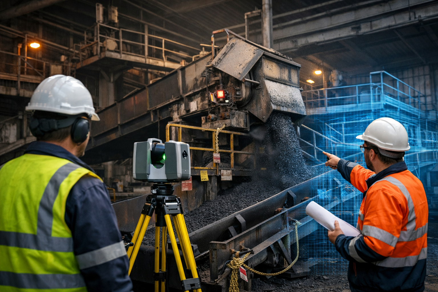
Coal plant shutdown engineering using a 3D laser scanner to capture conveyor and transfer chute infrastructure.

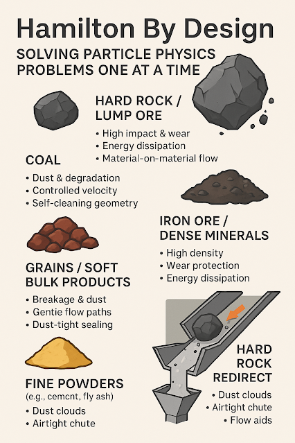
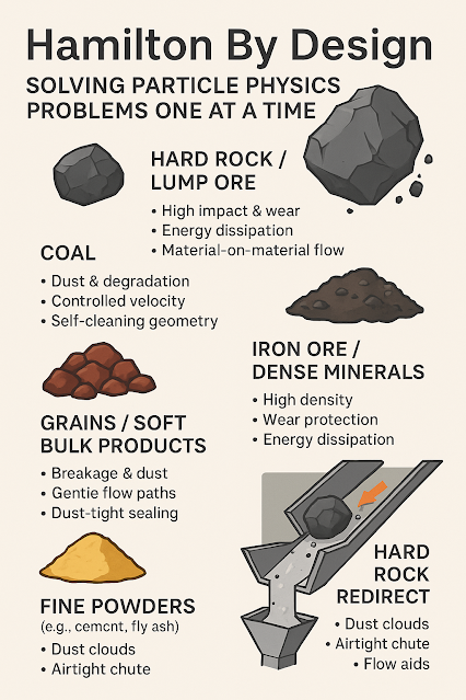
At Hamilton by Design, we believe that every bulk material transfer is an opportunity for improvement. What appears to be a simple flow of rock, coal, grain, or powder is, in reality, a particle physics problem waiting to be solved. By approaching these challenges with precision, creativity, and hands-on knowledge, we deliver chute designs that do more than move material โ€” they protect assets, enhance performance, and improve the bottom line.

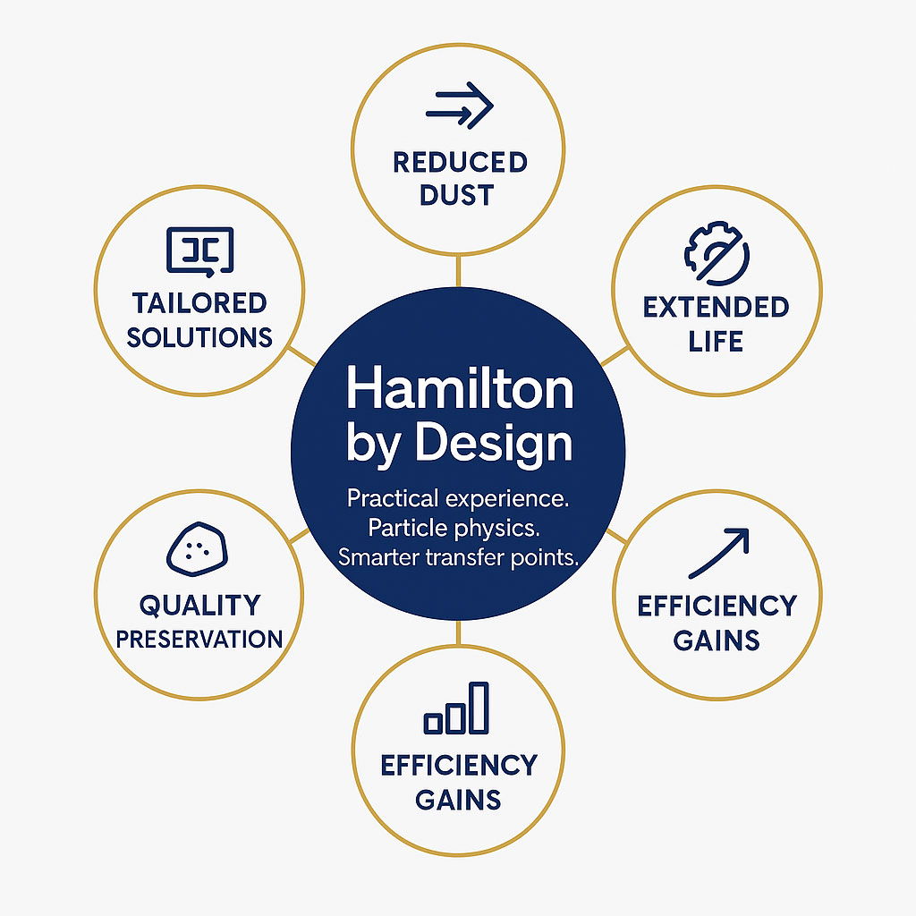
Infographic showing Hamilton By Design in a central blue circle with the text โ€˜Practical experience. Particle physics. Smarter transfer points.โ€™ Surrounding circles highlight benefits: reduced dust, extended life, efficiency gains, quality preservation, and tailored solutions.
3D LiDAR scanning and 3D modelling service button โ€” laser scanner capturing a point cloud for engineering and CAD modelling
Mechanical engineering services

We are a small, specialised company with a wealth of on-site experience. Our engineers have spent years in the field, watching, listening, and learning how different materials behave under real conditions. This raw experience gives us a unique advantage: we can see and understand particle flow first-hand, not just through numbers on a screen. While many large organisations rely solely on computer models, we combine advanced simulation with practical insight, ensuring solutions that work not only in theory but also in practice.

Our team thrives on solving the complex problems others overlook:

  • Redirecting hard rock at speed without spillage or damage.
  • Handling sticky coal without blockages or hang-ups.
  • Containing fine powders without dust plumes or health risks.
  • Transferring fragile grains without breakage or product loss.
  • Extending chute, liner, and belt life with robust material-on-material flow designs.

We approach every challenge with the mindset that your success is our success. When your plant runs reliably, safely, and efficiently, we succeed alongside you. Thatโ€™s why we design transfer points that:

  • Absorb and dissipate energy from high-impact lumps.
  • Control dust and minimise degradation for cleaner, safer operations.
  • Extend equipment life by reducing wear and maintenance.
  • Adapt to variability in feed size, flow, and moisture.
  • Boost throughput and availability by minimising stoppages.

In a world where margins are tight and environmental responsibility is critical, Hamilton by Design offers a personal, client-focused approach that puts performance and partnership at the centre. We are not a large organisation pushing generic solutions โ€” we are a dedicated team that listens, observes, and engineers smarter outcomes, one particle physics problem at a time.

Our clients:


For more information, Coal Chute Design

Hamilton By Design logo displayed on a blue tilted rectangle with a grey gradient background


Name
Would you like us to arrange a phone consultation for you?
Address
Reality Capture Brisbane title graphic with white text on a blue background promoting reality capture, LiDAR scanning and digital engineering services in Brisbane, Queensland.
3D Scanning Brisbane text graphic on a blue background promoting engineering-led laser scanning and reality capture services in Brisbane.

LiDAR Scanning Brisbane title graphic with white text on a blue background promoting terrestrial LiDAR scanning, point cloud capture and reality capture services in Brisbane, Queensland.
SolidWorks Brisbane title graphic with white text on a blue background promoting SolidWorks mechanical design, 3D CAD modelling and engineering drafting services in Brisbane, Queensland.


3D Scanning Sydney banner promoting engineering-grade 3D laser scanning, LiDAR scanning, and reality capture services by Hamilton By Design.
Mechanical Engineering Sydney banner with white text on a blue background representing Hamilton By Design's mechanical engineering services in Sydney.
Mechanical Drafting and 3D Modelling Sydney banner highlighting Hamilton By Design's CAD drafting, 3D modelling, and engineering design services in Sydney.

Mechanical Engineering | Structural Engineering


Designing for Developing Hazards: Lessons from the Derrimut Crane Collapse

Designing for Developing Hazards

Crane accidents are among the most visible reminders of the risks inherent in construction. The collapse of a crane at a data centre site in Derrimut, Melbourne, brought attention once again to the vulnerability of temporary lifting structures. While formal investigations are still underway, and no conclusions should be drawn prematurely, the event provides a valuable opportunity for reflection within the engineering community.

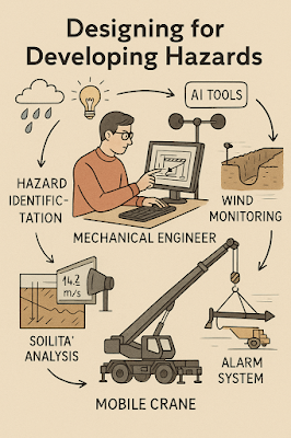
This article considers the collapse not as an isolated failure but as a case study in hazard identification. In particular, it highlights how mechanical engineers must adapt from a static, design-phase view of risk to a dynamic, real-time approach to hazard monitoring. Wind, soil stability, and load conditions are well-known hazards. But with modern tools โ€” including LiDAR scanning for obstacle detection โ€” engineers can move toward a future where developing hazards are continuously tracked, anticipated, and controlled.

From Hazard Identification to Live Hazard Monitoring

Hazard identification has traditionally been a design-phase process: engineers anticipate risks, apply safety factors, and create conservative margins. This remains essential. Yet the Derrimut collapse illustrates the limits of a static model in a dynamic environment.

Cranes are exposed to evolving hazards:

  • Wind gusts that change minute by minute.
  • Soil stability that shifts with rainfall, excavation, or groundwater.
  • Obstacles such as power lines or nearby structures, which can create cascading risks if struck.
  • Load dynamics, including swinging or sudden movement.

What is needed is a transition from hazard identification to hazard monitoring: a continuous loop where design assumptions are validated against real-time data, and where developing risks are detected before they become failures.

Wind Hazards: Predicting the Unpredictable

Wind is a leading cause of crane collapses. Engineers know the mathematics: pressure rises with the square of velocity. A 50 km/h gust exerts twice the force of a 35 km/h breeze.

Most cranes today are fitted with anemometers and alarms, but these are often basic: a single reading at a single point, with alarms sounding when preset thresholds are exceeded. This approach can miss:

  • Local gust variability along a long jib.
  • Interaction with crane orientation (wind hitting the broadside is more critical than aligned wind).
  • Forecasted conditions that could deteriorate within minutes.

Next-generation wind monitoring could include:

  • Multi-point sensor arrays on cranes.
  • Integration with Bureau of Meteorology gust forecasts.
  • AI models predicting when risk thresholds will be exceeded, not just reporting when they are crossed.
  • Automatic crane repositioning to minimise wind exposure.

This transforms alarms from reactive to predictive โ€” the difference between warning after a hazard is present and anticipating before it materialises.


Soil Hazards: Stability Under Load

Ground conditions are another silent but critical hazard. Outriggers may impose hundreds of kilonewtons on pads, meaning even small soil weaknesses can lead to tilting or overturning.

Engineering practice already includes soil investigations: boreholes, CPT, SPT, and FEA models. But these tests capture conditions before installation, not necessarily during operation. Soil strength can change due to rainfall, groundwater shifts, or nearby excavation.

Live soil monitoring can be achieved with:

  • Load cells under mats to track ground reactions.
  • Settlement gauges to detect tilt.
  • Piezometers for pore pressure during rain events.
  • Integrated warnings when ground resistance trends downward.

This approach acknowledges soil as a living hazard that changes daily.

LiDAR and Obstacle Detection: Power Lines and Proximity Hazards

One striking feature of the Derrimut collapse was the craneโ€™s boom striking power lines. Contact with utilities is a recurrent hazard in crane operations worldwide. While operators are trained to maintain exclusion zones, in practice visibility, fatigue, or unexpected boom movement can still lead to contact.

LiDAR scanning offers a solution.

  • How it works: LiDAR (Light Detection and Ranging) emits laser pulses to map surroundings in 3D with centimetre accuracy. Mounted on a crane, it can create a live digital map of nearby obstacles.
  • Application in cranes:
    • Detecting and mapping power lines, buildings, or scaffolding in the lift path.
    • Setting proximity alarms when a boom, hook, or load approaches a defined clearance.
    • Combining with wind data to predict if gusts could push the load into restricted zones.

In aviation, LiDAR and radar-based systems are standard for obstacle detection. In construction, adoption is patchy. Yet the technology exists, is cost-effective, and could dramatically reduce risks of contact with hazards like live power lines.

LiDARโ€™s strength lies not only in static mapping but in detecting movement โ€” for example, when a suspended load begins to swing toward a power line due to a gust. This is a quintessential developing hazard, one that static design could never fully capture.

Integrated Hazard Dashboards

Wind, soil, and LiDAR obstacle detection all provide valuable data. But their true power lies in integration. Imagine a crane operatorโ€™s cabin equipped with a single dashboard displaying:

  • Wind speeds and gust forecasts, colour-coded for risk.
  • Soil reaction forces under each outrigger, with alerts if settlement is trending.
  • LiDAR mapping of nearby structures and power lines, with real-time clearance zones.
  • Predictive risk models showing probability of instability or contact over the next 30 minutes.

This integration mirrors aviationโ€™s cockpit: multiple inputs fused into actionable guidance. For cranes, such systems could shift the operatorโ€™s role from reactive decision-maker to proactive risk manager.


AI as a Predictive Partner

Artificial Intelligence has a natural role in hazard monitoring:

  • Sensor fusion: combining wind, soil, and LiDAR inputs into coherent risk profiles.
  • Prediction: learning from past crane incidents to forecast when risks are likely to escalate.
  • Decision support: providing operators with clear options (โ€œsafe to continue lift for 20 minutesโ€ / โ€œhalt operations โ€” clearance margin < 1mโ€).

The challenge is balance. AI should not replace human oversight, but augment it. Over-reliance could create new vulnerabilities if operators become complacent. The design challenge is to build AI into systems that support human judgment rather than substitute for it.


Ethics and Engineering Responsibility

The Derrimut collapse underscores the ethical responsibility of mechanical engineers. Hazard identification is not just a design requirement; it is a matter of public safety. The profession has a duty to anticipate, detect, and control risks wherever possible.

The tools now exist to monitor developing hazards โ€” wind sensors, soil gauges, LiDAR scanners, and AI dashboards. If lives and infrastructure can be protected through wider adoption of these tools, then the question becomes one of responsibility: should they be optional, or mandatory?

Open Questions for the Future

  1. Would integrated live monitoring have reduced the risks at Derrimut?
  2. Should all cranes be fitted with LiDAR obstacle detection as standard?
  3. Do we already have enough technology, but lack regulation and enforcement?
  4. What role should AI play in balancing predictive insight with operator autonomy?

The Derrimut incident remains under investigation. No conclusions can be drawn about its specific cause until findings are published. Yet as a case study, it illustrates the broader point that hazards in crane operations are dynamic. Wind, soil, obstacles, and loads evolve minute by minute.

Mechanical engineers have the tools โ€” wind sensors, soil monitors, LiDAR scanners, integrated dashboards, and AI โ€” to detect these developing hazards. The challenge is to move from a culture of static design assumptions to one of continuous hazard monitoring.

The ultimate professional question is this: If aviation can integrate multiple systems to monitor and predict hazards, why canโ€™t construction do the same for cranes? And if we can, how soon will we accept the ethical responsibility to make it standard?

References and Further Reading

  • ISO 4301 / AS 1418 โ€” Crane standards covering stability and wind.
  • ISO 12480-1:2003 โ€” Safe use of cranes; includes environmental hazard monitoring.
  • WorkSafe Victoria Guidance Notes โ€” Crane safety management.
  • Holickรฝ & Retief (2017) โ€” Probabilistic treatment of wind action in structural design.
  • Nguyen et al. (2020) โ€” Real-time monitoring of crane foundation response under variable soil conditions.
  • Liebherr LICCON โ€” Example of integrated load and geometry monitoring.
  • FAA LLWAS โ€” Aviationโ€™s real-time wind shear alert system, model for construction.
  • Recent research in LiDAR obstacle detection (e.g., IEEE Transactions on Intelligent Transportation Systems) โ€” showing LiDARโ€™s potential in complex environments.
Hamilton By Design logo displayed on a blue tilted rectangle with a grey gradient background
3D LiDAR scanning and 3D modelling service button โ€” laser scanner capturing a point cloud for engineering and CAD modelling
Mechanical engineering services

Our clients:

Name
Would you like us to arrange a phone consultation for you?
Address

Structural Drafting

3D CAD Modelling Australia service banner for Hamilton By Design
Australian Drafting logo featuring bold white text reading "Australian Drafting" centred on a blue rounded rectangle background.
Engineering Governance title graphic featuring bold white text reading "Engineering Governance" centred on a blue rounded rectangle background.
Mechanical, Structural & Pipework Drafting service banner by Hamilton By Design featuring white text on a blue background.
Mechanical engineering services
Blue rounded button with the text โ€œSolidWorks Designโ€ in white.
Finite Element Analysis (FEA) engineering simulation button
3D LiDAR Scanning Darwin for engineering surveys, laser scanning, reality capture and point cloud modelling services
3D LiDAR Scanning Australia engineering services for laser scanning, reality capture, scan-to-CAD, Scan-to-BIM and as-built documentation across Australia
3D LiDAR scanning services on the Central Coast providing engineering-grade laser scanning, point cloud capture, scan-to-CAD modelling and industrial reality capture for infrastructure and industrial projects.
3D LiDAR Scanning Perth for engineering surveys, laser scanning, reality capture and point cloud modelling services
3D LiDAR Scanning Sydney for engineering surveys, laser scanning, reality capture and point cloud modelling services
3D LiDAR Scanning Brisbane for engineering surveys, laser scanning, reality capture and point cloud modelling services
3D LiDAR Scanning Canberra for engineering surveys, laser scanning, reality capture and point cloud modelling services
3D LiDAR Scanning Newcastle for engineering surveys, laser scanning, reality capture and point cloud modelling services
3D LiDAR Scanning Adelaide for engineering surveys, laser scanning, reality capture and point cloud modelling services

Mechanical Drafting

3D Laser Scanning

Mechanical Engineering

Consulting Engineers

The Importance of AS 3990 in Mechanical Equipment Steelwork

In the world of engineering, adhering to standards is more than just a formality; itโ€™s a fundamental aspect of ensuring safety, reliability, and efficiency. One such critical standard is AS 3990, “Mechanical Equipment โ€“ Steelwork.” This guideline plays a vital role in the design and construction of steel structures for mechanical systems, providing the framework for materials selection, construction practices, and stress analysis. Ignoring AS 3990 can lead to a host of issues, from structural failures to safety hazards, yet itโ€™s a challenge that some organizations still face. By contrast, companies like Hamilton By Design have built a reputation for excellence by consistently applying these standards in their projects, ensuring optimal outcomes for their clients.

The Risks of Ignoring AS 3990

One of the most alarming consequences of bypassing AS 3990 is the heightened risk of structural failure. Mechanical equipment steelwork is often subjected to extreme stresses and environmental conditions, and without proper design parameters, the results can be catastrophic. Whether itโ€™s the collapse of a support structure or the malfunction of a mechanical component, the costโ€”both human and financialโ€”is often irreparable.

In addition to physical failures, neglecting AS 3990 invites a host of compliance and legal issues. Regulatory bodies across industries mandate adherence to such standards to protect workers and ensure operational safety. Non-compliance can lead to fines, project delays, or even legal action, tarnishing the reputation of those involved.ย 

The impact doesnโ€™t stop there. Poorly designed steelwork can suffer from premature wear and fatigue, significantly reducing the lifespan of the equipment. This leads to frequent maintenance, unplanned downtime, and increased costsโ€”a scenario no company wants to face. Moreover, these recurring issues not only affect the bottom line but also compromise the safety of workers, posing risks of injury or fatality. Finally, the reputational damage from delivering substandard systems can be devastating, as it erodes client trust and tarnishes an organizationโ€™s standing in the industry.

Hamilton By Design: A Commitment to Excellence

Faced with these potential pitfalls, an engineering company like Hamilton By Design offers a reassuring solution. With extensive experience in mechanical design and steelwork, they prioritize adherence to AS 3990 in every project. This commitment translates into tangible benefits for their clients and sets them apart in the industry.

Hamilton By Design approaches every project with structural integrity at the forefront. By leveraging advanced modeling tools and stress analysis techniques, they ensure that every design adheres to the stringent guidelines of AS 3990. Their expertise spans diverse industries, enabling them to tailor solutions that are both robust and reliable.

Compliance is another area where Hamilton By Design excels. The team stays up-to-date with the latest iterations of AS 3990, incorporating these requirements seamlessly into their work. This not only streamlines the approval process but also gives clients the confidence that their projects meet all necessary regulatory standards.

Material selection and durability are cornerstones of the companyโ€™s design philosophy. By carefully analyzing the operational stresses and environmental factors that each structure will face, Hamilton By Design creates systems that are built to last. This focus on longevity reduces the need for maintenance and ensures uninterrupted performance, saving clients time and money.

Safety is non-negotiable for Hamilton By Design. Every project undergoes rigorous risk assessments to identify and mitigate potential hazards. By adhering to AS 3990โ€™s safety protocols, the company not only protects workers but also fosters a culture of trust and reliability.

The Advantages of AS 3990 Compliance

The advantages of working with engineers who consult AS 3990 are clear. First and foremost, it ensures structural reliability. Steelwork designed under this standard can handle expected loads and stresses with ease, delivering dependable performance across a range of applications. For Hamilton By Design, this translates into designs that consistently exceed client expectations.

Regulatory compliance is another significant benefit. Projects that adhere to AS 3990 face fewer hurdles during inspections, avoiding costly delays and potential penalties. Hamilton By Designโ€™s meticulous approach to compliance ensures smooth project execution, freeing clients to focus on their core objectives.

Optimized design is yet another hallmark of AS 3990. By balancing safety, functionality, and cost-efficiency, the standard empowers engineers to deliver solutions that are both practical and innovative. Hamilton By Design takes this a step further by using advanced tools and methodologies to craft designs that align perfectly with their clientsโ€™ operational goals.

Safety, of course, remains a top priority. AS 3990 includes comprehensive guidelines for risk minimization, creating a safer environment for workers and operators. Hamilton By Designโ€™s adherence to these principles underscores their commitment to safeguarding everyone involved in their projects.

Cost savings and increased equipment lifespan are additional advantages of compliance. Properly designed steelwork not only reduces maintenance needs but also enhances durability, maximizing the return on investment for clients. For Hamilton By Design, these outcomes are the natural result of their dedication to quality and precision.

Real-World Applications

Hamilton By Designโ€™s expertise in applying AS 3990 is evident in their extensive portfolio. For instance, in a mining project involving heavy conveyor systems, the company used AS 3990 to identify critical stress points and optimize the design for dynamic loads. The result was a durable support structure that minimized maintenance and exceeded client expectations.

Similarly, in an industrial manufacturing facility, Hamilton By Design tackled the challenge of custom steelwork for robotic assembly lines. By adhering to AS 3990, they ensured that the structures could withstand repetitive stresses and environmental factors, enhancing both safety and efficiency.

Their experience extends to renewable energy projects as well. In designing steel frameworks for wind turbine foundations, Hamilton By Design accounted for wind loads, fatigue stresses, and environmental conditions, delivering solutions that met stringent safety and performance requirements.

Conclusion

Ignoring AS 3990 is a risk no company should take. The challengesโ€”from structural failures and compliance issues to safety hazards and reputational damageโ€”are simply too great. By contrast, working with experienced engineers who prioritize this standard offers a host of benefits, from enhanced reliability and safety to cost savings and competitive advantage.

Hamilton By Design exemplifies the best practices in applying AS 3990, turning potential challenges into opportunities for innovation and excellence. Their commitment to quality, compliance, and client satisfaction ensures that every project not only meets but exceeds industry standards. For organizations seeking dependable, high-performing mechanical equipment steelwork, Hamilton By Design is the partner of choice.

For More information contact Hamilton By Design – Email [email protected]

3D LiDAR scanning and 3D modelling service button โ€” laser scanner capturing a point cloud for engineering and CAD modelling
Mechanical engineering services

Our Clients:

Name
Would you like us to arrange a phone consultation for you?
Address

3D CAD in Sydney

3D Construction Scan in Sydney

https://www.hamiltonbydesign.com.au/home/engineering-services/3d-laser-scanning/3d-scanning-sydney/3d-point-cloud-modelling-in-sydney/

3D LiDAR Laser Scanning & Drafting Services in Chatswood & Greater Sydney

Finite Element Analysis (FEA) engineering simulation button
Mechanical engineering services

3D Scanning Sydney banner promoting engineering-grade 3D laser scanning, LiDAR scanning, and reality capture services by Hamilton By Design.
Mechanical Engineering Sydney banner with white text on a blue background representing Hamilton By Design's mechanical engineering services in Sydney.
Mechanical Drafting and 3D Modelling Sydney banner highlighting Hamilton By Design's CAD drafting, 3D modelling, and engineering design services in Sydney.

Mechanical Engineering | Structural Engineering