Wearable 3D Scanners vs Engineering-Grade LiDAR

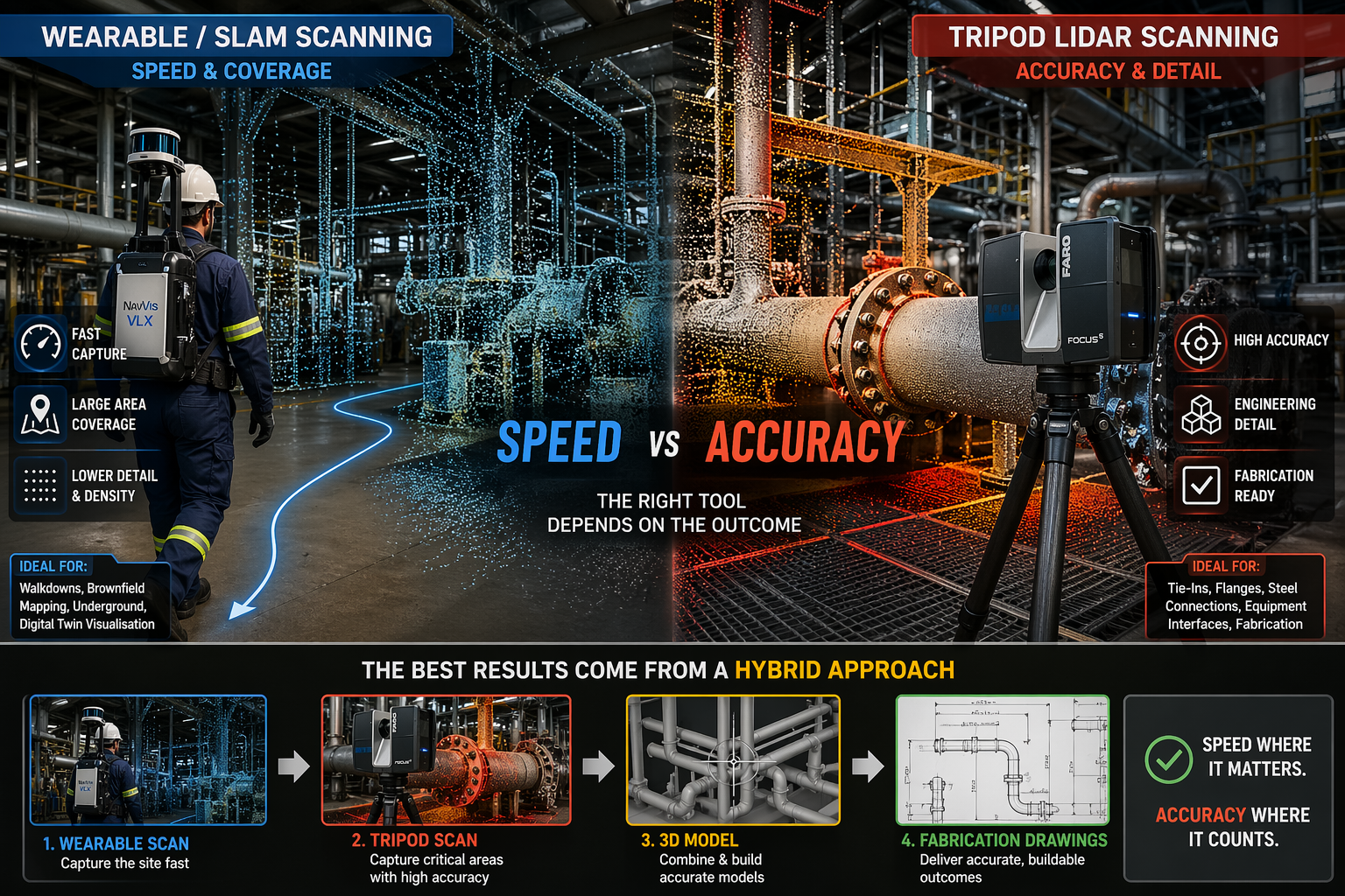
Wearable SLAM lidar scanner compared with tripod laser scanner in an industrial plant showing speed versus accuracy in point cloud data

Wearable 3D Scanners vs LiDAR | Engineering Accuracy Explained

Why Speed Doesnโ€™t Always Mean Accuracy in Industrial Scanning

Blue 3D LiDAR scanner icon on a tripod with scanning waves

Wearable 3D scanning systems โ€” often referred to as backpack or body-mounted LiDAR scanners โ€” are becoming increasingly common across mining, construction, and industrial environments.

These systems allow an operator to walk through a site and capture data in real time, significantly reducing time spent in the field.

However, while speed has improved, an important question remains:

Are wearable scanners suitable for engineering and fabrication work?

At Hamilton By Design, we take an engineering-led approach to scanning. The answer is not as simple as many vendors suggest.


3D LiDAR scanning and 3D modelling service button โ€” laser scanner capturing a point cloud for engineering and CAD modelling
Mechanical engineering services

What Are Wearable 3D Scanners?

Wearable scanners, also known as SLAM LiDAR systems, are designed to be worn while walking through a site.

They typically use a combination of:

  • LiDAR sensors
  • Cameras
  • Inertial Measurement Units (IMU)
  • SLAM (Simultaneous Localisation and Mapping) algorithms

This allows the system to generate a continuous 3D point cloud without the need for tripod setups or survey targets.

In simple terms, the operator becomes the scanner.


The Key Advantage: Speed

The main advantage of wearable systems is speed.

They allow for:

  • Rapid site capture
  • Minimal setup time
  • Scanning of complex or confined environments
  • Efficient coverage of large areas

For walkdowns, site familiarisation, and early-stage layouts, wearable scanning is highly effective.


The Trade-Off: Accuracy and Detail

While wearable systems offer speed, they come with trade-offs.

Wearable SLAM scanners typically produce:

  • Lower point density
  • Reduced edge definition
  • Positional drift over longer distances

In contrast, traditional terrestrial LiDAR scanners provide:

  • High-density point clouds
  • Sharp and well-defined geometry
  • Millimetre-level accuracy
  • Repeatable and verifiable results

Why This Matters for Engineering

In industrial environments, scan data is not just for visualisation. It is used for:

  • Design modelling
  • Clash detection
  • Fabrication drawings
  • Installation planning

If the data lacks accuracy, it can lead to:

  • Misaligned pipework
  • Incorrect steel fabrication
  • Costly rework during shutdowns

A model that looks correct is not the same as a model that is correct.


Where Wearable Scanning Works Best

Wearable systems are well suited to:

  • Large-scale site capture
  • Underground environments
  • Brownfield walkdowns
  • Asset mapping
  • Digital twin visualisation

They provide excellent coverage and speed, but are not always suitable for detailed engineering work.


Where Engineering-Grade LiDAR Is Essential

Tripod-based LiDAR scanning is critical for:

  • Tie-in points
  • Flanges and pipe interfaces
  • Structural steel connections
  • Equipment interfaces
  • Fabrication-ready modelling

These are areas where millimetre-level accuracy is required.


The Reality: A Hybrid Approach

The most effective approach is not choosing one system over the other, but combining both.

A typical workflow includes:

  • Wearable scanning to capture the full site quickly
  • Tripod LiDAR scanning to capture critical areas with high accuracy

This provides both speed and precision.


Engineering-Led Scanning vs Fast Scanning

There is a common misconception that faster scanning leads to better outcomes.

In reality:

  • Fast data is only useful if it is accurate
  • Point clouds must support engineering decisions
  • Accuracy must align with project risk

At Hamilton By Design, the focus is on delivering:

  • Engineering-grade outputs
  • Scan-to-model workflows
  • Fabrication-ready data

Our clients

3D CAD Modelling Australia service banner for Hamilton By Design

Talk to us – Contact Us

Name
Would you like us to arrange a phone consultation for you?
Address

Inspired By Jim

3D CAD Modelling Australia service banner for Hamilton By Design
Australian Drafting logo featuring bold white text reading "Australian Drafting" centred on a blue rounded rectangle background.
Engineering Governance title graphic featuring bold white text reading "Engineering Governance" centred on a blue rounded rectangle background.
Mechanical, Structural & Pipework Drafting service banner by Hamilton By Design featuring white text on a blue background.
Mechanical engineering services
Blue rounded button with the text โ€œSolidWorks Designโ€ in white.
Finite Element Analysis (FEA) engineering simulation button
3D LiDAR Scanning Darwin for engineering surveys, laser scanning, reality capture and point cloud modelling services
3D LiDAR Scanning Australia engineering services for laser scanning, reality capture, scan-to-CAD, Scan-to-BIM and as-built documentation across Australia
3D LiDAR scanning services on the Central Coast providing engineering-grade laser scanning, point cloud capture, scan-to-CAD modelling and industrial reality capture for infrastructure and industrial projects.
3D LiDAR Scanning Perth for engineering surveys, laser scanning, reality capture and point cloud modelling services
3D LiDAR Scanning Sydney for engineering surveys, laser scanning, reality capture and point cloud modelling services
3D LiDAR Scanning Brisbane for engineering surveys, laser scanning, reality capture and point cloud modelling services
3D LiDAR Scanning Canberra for engineering surveys, laser scanning, reality capture and point cloud modelling services
3D LiDAR Scanning Newcastle for engineering surveys, laser scanning, reality capture and point cloud modelling services
3D LiDAR Scanning Adelaide for engineering surveys, laser scanning, reality capture and point cloud modelling services

Surfboard Digital Engineering

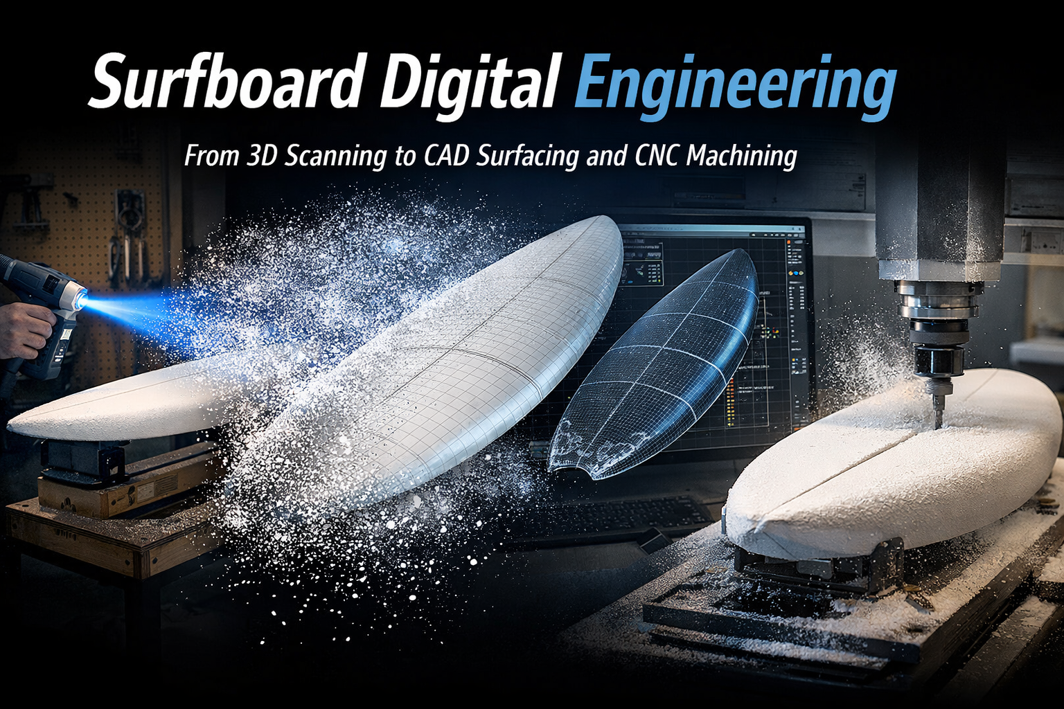
surfboard digital engineering workflow showing 3D scanning CAD modelling and CNC machining

From Surfboard Scan to CNC Manufacturing

Surfboard performance is defined by geometry. Small variations in rocker, rail profile, deck shape and bottom contours can significantly influence how a board performs in the water.

Hamilton By Design provides digital engineering services for surfboard design and manufacturing, helping convert physical surfboards into precise digital models suitable for analysis, modification and CNC machining.

Our team combines high-accuracy 3D scanning, advanced CAD surfacing and CNC programming expertise to support the complete workflow from physical surfboard to manufacturable digital model.

This integrated capability allows shapers, designers and manufacturers to move confidently from existing board โ†’ digital design โ†’ CNC machined blank.


A Complete Digital Workflow for Surfboard Manufacturing

Hamilton By Design provides a complete workflow that connects scanning, modelling and manufacturing preparation.

Typical projects move through the following stages.

surfboard digital engineering workflow showing 3D scanning CAD modelling and CNC machining

1. Surfboard Geometry Capture

Using high-resolution scanning technology, the physical surfboard geometry is captured to create a digital representation of the board.

This process records the complete board shape including:

  • rocker profile
  • deck contours
  • bottom contours
  • rail transitions
  • nose and tail geometry
  • fin placement and alignment

Related page: 3D Scanning of Surfboards


2. Point Cloud Processing

The raw scan data is processed and aligned to produce a clean digital representation of the surfboard.

This step ensures that the geometry can be used reliably for modelling, comparison and design development.

Processed data may be delivered as:

  • point clouds
  • mesh models
  • reference geometry for CAD modelling

3. Surfboard Surface Development

Surfboards are complex shapes that rely on smooth continuous surfaces.

Our team specialises in 3D CAD surfacing, allowing the scanned geometry to be converted into smooth, manufacturable surfaces suitable for design development or machining.

This stage may include:

  • surface reconstruction
  • symmetry correction
  • rocker curve analysis
  • rail profile development
  • design adjustments

Related page: Surfboard 3D Modelling and Surface Development


4. CNC Programming and Manufacturing Preparation

Once the surfboard model has been developed, CNC machining programs can be created for foam blank machining.

Our qualified CNC programmers prepare machining strategies including:

  • toolpath generation
  • cutter selection
  • machining strategies for foam blanks
  • blank positioning and setup
  • CNC code preparation

Related page: CNC Programming for Surfboard Manufacturing


Our Integrated Engineering Capability

Hamilton By Design provides a one-stop digital engineering workflow for surfboard manufacturing.

Our team includes:

3D Scanning Specialists

Capturing accurate geometry of existing surfboards using professional scanning technology.

Advanced 3D Modelling and Surfacing

Developing precise surfboard geometry using professional CAD modelling tools capable of producing smooth, hydrodynamically fair surfaces.

Qualified CNC Programmers

Preparing machining programs and strategies suitable for CNC shaping of surfboard blanks.

Manufacturing Workflow Support

Helping surfboard manufacturers move from physical board โ†’ digital model โ†’ CNC machining with confidence.

This integrated capability ensures that the digital data produced is not only accurate, but also suitable for downstream manufacturing processes.


Applications of Surfboard Digital Engineering

Our services can support a wide range of surfboard design and manufacturing applications.

Reverse Engineering Successful Boards

High-performing surfboards can be digitally captured and recreated for further development or reproduction.

Surfboard Design Development

Digital models allow designers to refine rocker curves, rails and bottom contours before machining.

CNC Manufacturing Preparation

Accurate digital models allow CNC machines to cut surfboard blanks with greater confidence and repeatability.

Archiving Surfboard Designs

Surfboard designs can be digitally preserved for future manufacturing or development.

Design Comparison

Digital models allow comparison between different board designs to better understand performance differences.


Why Digital Engineering Matters in Surfboard Design

Traditionally, surfboards have been shaped by hand using a combination of experience and intuition.

While this approach continues to play an important role in shaping culture, modern surfboard manufacturing increasingly relies on digital tools.

Digital workflows provide several advantages:

  • repeatable board production
  • accurate reproduction of successful designs
  • improved design development
  • better collaboration between designer and manufacturer
  • reduced manufacturing variation

Hamilton By Design helps bridge the gap between traditional shaping knowledge and modern digital manufacturing tools.


Scan to CNC Workflow

Existing Surfboard
โ†“
3D Scanning
โ†“
Point Cloud Processing
โ†“
CAD Surface Development
โ†“
CNC Programming
โ†“
Machined Surfboard Blank


Related Services

Hamilton By Design provides a range of related services that support digital engineering and manufacturing workflows.

These include:

  • 3D laser scanning services
  • scan-to-CAD modelling
  • reverse engineering
  • advanced surface modelling
  • CNC programming
  • manufacturing preparation

Hamilton By Design logo displayed on a blue tilted rectangle with a grey gradient background

3D LiDAR scanning and 3D modelling service button โ€” laser scanner capturing a point cloud for engineering and CAD modelling
Mechanical engineering services

Talk With Hamilton By Design

If you are looking to digitise a surfboard design, reverse engineer an existing board, or prepare a surfboard model for CNC machining, Hamilton By Design can assist.

Our team combines engineering-grade scanning, advanced CAD surfacing and practical CNC programming expertise to support the full digital workflow.

Contact Hamilton By Design to discuss your project.

Name
Would you like us to arrange a phone consultation for you?
Address
3D CAD Modelling Australia service banner for Hamilton By Design
Finite Element Analysis (FEA) engineering simulation button
Mechanical engineering services

LiDAR Accuracy in Engineering Applications

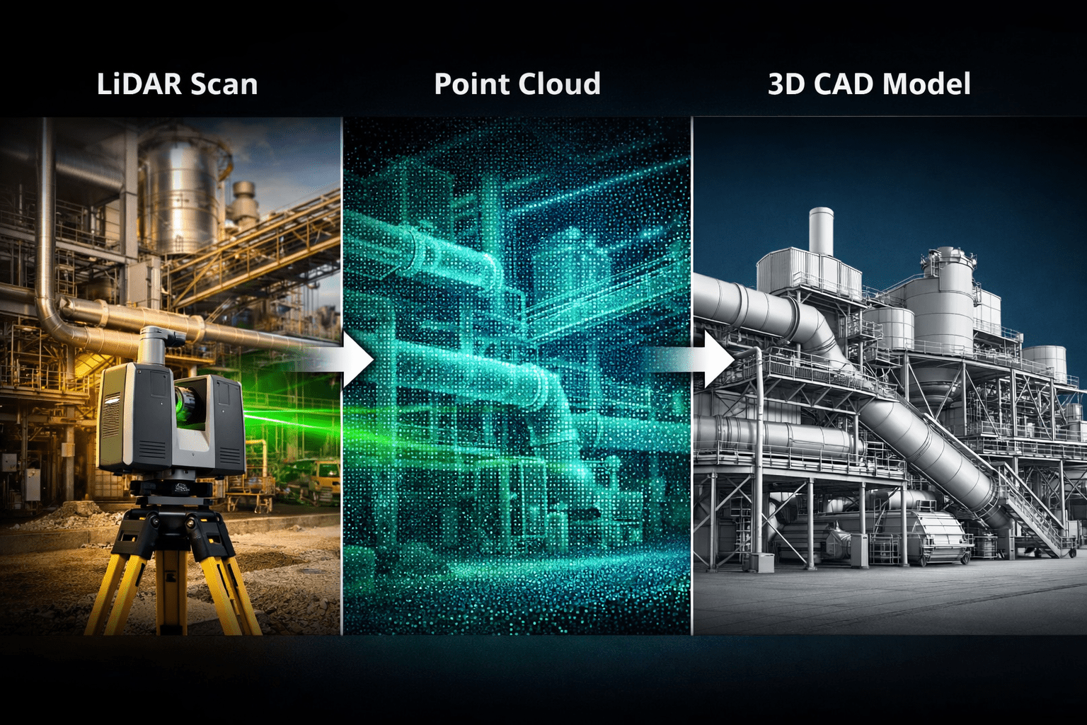
LiDAR scanning workflow showing an engineering laser scanner capturing industrial infrastructure and converting the data into a point cloud and CAD model.

Understanding LiDAR Accuracy for Engineering Projects

In modern engineering projects, capturing accurate measurements of existing infrastructure is critical before design work begins. LiDAR accuracy engineering plays a central role in this process by allowing engineers to capture millions of precise measurements of structures, plant equipment, and terrain in a matter of minutes.

LiDAR (Light Detection and Ranging) technology uses laser pulses to measure distances to surfaces and create a detailed 3D point cloud model of the scanned environment. These datasets provide engineers with reliable dimensional information that can be used for plant upgrades, mechanical design, structural modifications, and site documentation.

At Hamilton By Design, LiDAR scanning is commonly used to capture existing conditions for mining infrastructure, industrial facilities, and complex engineering environments.

You can learn more about our scanning services here:


What Determines LiDAR Accuracy in Engineering?

Several factors influence the overall accuracy of LiDAR scanning in engineering applications.

1. Scanner Hardware Accuracy

Modern engineering-grade scanners typically provide millimetre-level accuracy. High-end terrestrial LiDAR scanners commonly achieve:

โ€ข ยฑ1โ€“3 mm accuracy at 10 metres
โ€ข ยฑ2โ€“6 mm accuracy across larger industrial spaces
โ€ข Millions of points captured per second

These scanners allow engineers to measure structures without physical contact while maintaining high dimensional reliability.

Hamilton By Design uses professional scanning workflows designed specifically for engineering environments such as mining plants, conveyors, pump stations, and processing infrastructure.

More about these applications:

https://www.hamiltonbydesign.com.au/home/engineering-services/3d-laser-scanning/3d-laser-scanning-across-australia


2. Scan Setup and Registration

Accuracy is not only determined by the scanner itself. It also depends on how the scans are set up and aligned together.

During a project, multiple scans are captured from different positions and then registered together to create a complete 3D dataset.

Proper registration ensures:

โ€ข accurate alignment of overlapping scans
โ€ข minimal cumulative error across large sites
โ€ข reliable geometry for engineering modelling

In mining plants or processing facilities, dozens or sometimes hundreds of scans may be combined to create a full site model.


3. Surface Conditions and Environment

The environment being scanned also affects measurement accuracy.

Common factors include:

โ€ข reflective metal surfaces
โ€ข dust or airborne particles
โ€ข complex pipework and structural steel
โ€ข long scanning distances

Experienced operators account for these factors by selecting optimal scan locations and controlling the scanning workflow.

This is particularly important during shutdown projects or plant upgrades, where accurate measurements must be captured quickly.

See how scanning supports shutdown projects:


From LiDAR Data to Engineering Models

Once scanning is complete, the raw point cloud data is processed and converted into engineering models.

Typical workflow includes:

  1. Site LiDAR scanning
  2. Point cloud registration
  3. Data cleaning and segmentation
  4. Conversion to engineering models
  5. CAD design and drafting

The result is a highly accurate digital representation of the existing infrastructure, allowing engineers to design modifications with confidence.

A detailed explanation of this process can be found here:


Why LiDAR Accuracy Matters in Engineering Design

The accuracy of LiDAR scanning directly impacts engineering outcomes.

High-quality scan data helps engineers:

โ€ข avoid clashes with existing structures
โ€ข reduce site rework during installation
โ€ข shorten shutdown durations
โ€ข design prefabricated components
โ€ข improve documentation of existing assets

For mining and industrial environments, this level of accuracy significantly reduces project risk.

You can also read more about capturing existing conditions before plant upgrades here:


LiDAR Accuracy vs Traditional Measurement

Traditional measurement methods often rely on manual tape measurements, total stations, or site sketches.

While useful, these methods can introduce gaps in documentation.

LiDAR scanning provides several advantages:

MethodTypical AccuracyData DensitySite Time
Manual measurementVariableLowHigh
Total station surveyHighMediumModerate
LiDAR scanningMillimetre-levelExtremely HighVery Fast

Because LiDAR captures millions of measurement points, engineers gain a complete digital record of the site rather than a limited set of measurements.


LiDAR Accuracy for Mining and Industrial Engineering

Industries that benefit most from LiDAR accuracy include:

โ€ข mining operations
โ€ข mineral processing plants
โ€ข pump stations
โ€ข materials handling systems
โ€ข heavy industrial facilities

These environments typically contain complex pipework, structural steel, and equipment layouts where traditional measurement can be difficult.

Engineering-grade scanning provides a reliable foundation for future design work.


Engineering Applications of LiDAR Scanning

Some common engineering applications include:

โ€ข plant upgrade design
โ€ข piping modifications
โ€ข structural steel design
โ€ข conveyor and materials handling systems
โ€ข pump and mechanical equipment installations
โ€ข shutdown planning and prefabrication

At Hamilton By Design, these datasets are frequently converted into SolidWorks engineering models used for mechanical design and fabrication documentation.


The accuracy of LiDAR scanning in engineering applications has transformed how engineers capture and document complex infrastructure.

With millimetre-level accuracy, LiDAR allows engineering teams to build precise digital models of existing environments and design upgrades with confidence.

For industries such as mining and heavy industrial processing, this capability reduces project risk, improves design reliability, and enables faster project delivery.

Hamilton By Design provides engineering-grade LiDAR scanning services to support plant upgrades, shutdown projects, and mechanical design across Australia.

3D LiDAR scanning and 3D modelling service button โ€” laser scanner capturing a point cloud for engineering and CAD modelling
Mechanical engineering services
Name
Would you like us to arrange a phone consultation for you?
Address
Hamilton By Design logo displayed on a blue tilted rectangle with a grey gradient background
3D CAD Modelling Australia service banner for Hamilton By Design
Australian Drafting logo featuring bold white text reading "Australian Drafting" centred on a blue rounded rectangle background.
Engineering Governance title graphic featuring bold white text reading "Engineering Governance" centred on a blue rounded rectangle background.
Mechanical, Structural & Pipework Drafting service banner by Hamilton By Design featuring white text on a blue background.
Mechanical engineering services
Blue rounded button with the text โ€œSolidWorks Designโ€ in white.
Finite Element Analysis (FEA) engineering simulation button
3D LiDAR Scanning Darwin for engineering surveys, laser scanning, reality capture and point cloud modelling services
3D LiDAR Scanning Australia engineering services for laser scanning, reality capture, scan-to-CAD, Scan-to-BIM and as-built documentation across Australia
3D LiDAR scanning services on the Central Coast providing engineering-grade laser scanning, point cloud capture, scan-to-CAD modelling and industrial reality capture for infrastructure and industrial projects.
3D LiDAR Scanning Perth for engineering surveys, laser scanning, reality capture and point cloud modelling services
3D LiDAR Scanning Sydney for engineering surveys, laser scanning, reality capture and point cloud modelling services
3D LiDAR Scanning Brisbane for engineering surveys, laser scanning, reality capture and point cloud modelling services
3D LiDAR Scanning Canberra for engineering surveys, laser scanning, reality capture and point cloud modelling services
3D LiDAR Scanning Newcastle for engineering surveys, laser scanning, reality capture and point cloud modelling services
3D LiDAR Scanning Adelaide for engineering surveys, laser scanning, reality capture and point cloud modelling services

Accuracy of LiDAR Scanning for Engineering Applications

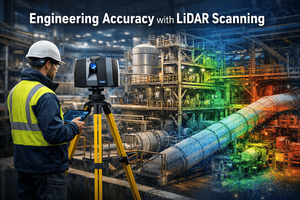
Industrial engineer operating a LiDAR laser scanner capturing high-accuracy point cloud data of a processing plant for engineering design and infrastructure upgrades.

Modern engineering projects increasingly rely on accurate digital representations of existing infrastructure before design, fabrication, or modification begins. One of the most powerful technologies enabling this is LiDAR scanning (Light Detection and Ranging).

At Hamilton By Design, LiDAR scanning is used to capture engineering-grade point cloud data of industrial facilities, mining infrastructure, processing plants, and mechanical systems across Australia.

Understanding the accuracy of LiDAR scanning is essential for engineers, project managers, and asset owners when planning upgrades or modifications to existing facilities.


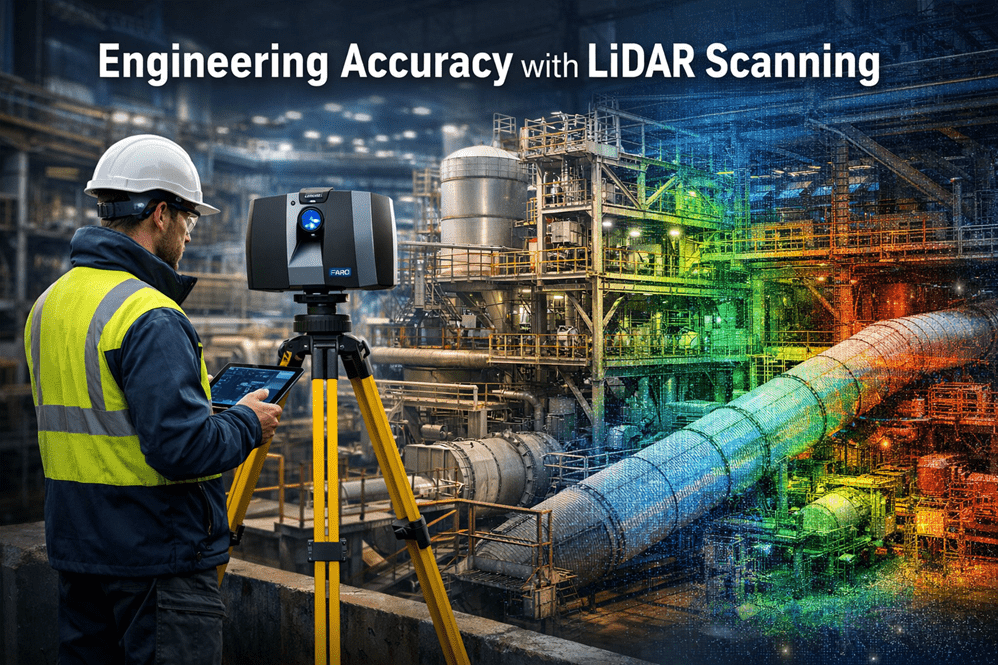
LiDAR scanning of industrial infrastructure with a 3D point cloud overlay showing engineering-grade measurement accuracy.

What is LiDAR Scanning?

LiDAR scanning works by emitting thousands of laser pulses per second. These pulses strike surrounding surfaces and return to the scanner, allowing precise calculation of distance.

The result is a dense three-dimensional point cloud that captures the exact geometry of an environment.

This digital dataset can then be used for:

โ€ข Engineering modelling
โ€ข Plant layout verification
โ€ข Clash detection
โ€ข Structural analysis
โ€ข Reverse engineering
โ€ข Retrofit design

At Hamilton By Design, these datasets are commonly converted into engineering models and SolidWorks design geometry using our established workflow.

Learn more about this process here:

Point Cloud to Engineering Model Workflow
https://www.hamiltonbydesign.com.au/point-cloud-to-engineering-model-workflow/


Typical Accuracy of Engineering LiDAR Scanning

The accuracy of LiDAR scanning depends on several factors including the scanner type, range to the object, scanning environment, and control methodology.

Typical engineering-grade terrestrial LiDAR systems achieve:

ParameterTypical Accuracy
Scanner measurement accuracyยฑ1 mm to ยฑ3 mm
Registered scan network accuracyยฑ2 mm to ยฑ6 mm
Large plant scan accuracyยฑ5 mm to ยฑ10 mm

For most industrial engineering applications, this level of accuracy is more than sufficient to support:

โ€ข Structural steel modifications
โ€ข Pipework routing and tie-ins
โ€ข Mechanical equipment installation
โ€ข Conveyor and materials handling upgrades
โ€ข Plant shutdown engineering works


Factors That Affect LiDAR Accuracy

Although LiDAR scanning can achieve extremely high accuracy, several practical factors influence final results.

Scan Resolution

Higher resolution scanning increases the number of measured points and improves detail, but also increases processing time and file size.

Distance to Target

Accuracy decreases slightly as the distance between the scanner and the object increases. Industrial scanning programs typically maintain distances between 5โ€“40 metres.

Scan Registration

Multiple scans must be aligned together to form a complete dataset. Proper registration and survey control ensures that the final point cloud remains accurate across large areas.

Surface Conditions

Highly reflective, transparent, or moving surfaces may introduce noise or missing data within the scan.


Why Accuracy Matters for Engineering Projects

Engineering projects often involve modifying existing assets that may have been constructed decades ago.

Original drawings may be missing, outdated, or inaccurate.

By capturing true existing conditions, LiDAR scanning reduces risk during design and construction.

Benefits include:

โ€ข Reduced site rework
โ€ข Fewer installation clashes
โ€ข Faster shutdown execution
โ€ข Improved fabrication accuracy
โ€ข Reduced project uncertainty

This is why many engineering teams now perform scanning before commencing plant upgrades.

Capture Existing Conditions Before Plant Upgrades
https://www.hamiltonbydesign.com.au/capture-existing-conditions-before-plant-upgrades/


LiDAR Scanning for Mining and Industrial Infrastructure

Industries where LiDAR scanning is particularly valuable include:

โ€ข Mining and mineral processing
โ€ข Water and wastewater facilities
โ€ข Power generation plants
โ€ข Heavy manufacturing facilities
โ€ข Materials handling systems

At Hamilton By Design, scanning is commonly used to support:

โ€ข Shutdown planning
โ€ข Structural modifications
โ€ข Mechanical equipment upgrades
โ€ข Brownfield engineering projects

Learn more about our scanning services across Australia:

Engineering Grade 3D Laser Scanning for Mining and Industrial Projects
https://www.hamiltonbydesign.com.au/home/engineering-grade-3d-laser-scanning-mining-industrial/


From Scan Data to Engineering Design

Once captured, LiDAR data becomes the foundation for digital engineering workflows.

Point clouds can be converted into:

โ€ข SolidWorks models
โ€ข Structural steel models
โ€ข Pipe routing layouts
โ€ข Mechanical equipment models
โ€ข Digital twins of plant infrastructure

This allows engineers to design modifications directly against the existing environment, dramatically reducing project risk.


Hamilton By Design logo displayed on a blue tilted rectangle with a grey gradient background

Conclusion

LiDAR scanning has become an essential tool for modern engineering projects, providing millimetre-level accuracy when capturing existing infrastructure.

When combined with experienced engineering workflows, LiDAR enables faster, safer, and more reliable plant upgrades.

At Hamilton By Design, we specialise in transforming high-accuracy LiDAR data into practical engineering models and design solutions for mining, industrial, and infrastructure projects.


Need LiDAR Scanning for Your Project?

Hamilton By Design provides engineering-grade 3D laser scanning services across Australia to support plant upgrades, shutdown projects, and infrastructure modifications.

Learn more about our services here:

3D LiDAR scanning and 3D modelling service button โ€” laser scanner capturing a point cloud for engineering and CAD modelling
Mechanical engineering services
Name
Would you like us to arrange a phone consultation for you?
Address
3D CAD Modelling Australia service banner for Hamilton By Design
Australian Drafting logo featuring bold white text reading "Australian Drafting" centred on a blue rounded rectangle background.
Engineering Governance title graphic featuring bold white text reading "Engineering Governance" centred on a blue rounded rectangle background.
Mechanical, Structural & Pipework Drafting service banner by Hamilton By Design featuring white text on a blue background.
Mechanical engineering services
Blue rounded button with the text โ€œSolidWorks Designโ€ in white.
Finite Element Analysis (FEA) engineering simulation button
3D LiDAR Scanning Darwin for engineering surveys, laser scanning, reality capture and point cloud modelling services
3D LiDAR Scanning Australia engineering services for laser scanning, reality capture, scan-to-CAD, Scan-to-BIM and as-built documentation across Australia
3D LiDAR scanning services on the Central Coast providing engineering-grade laser scanning, point cloud capture, scan-to-CAD modelling and industrial reality capture for infrastructure and industrial projects.
3D LiDAR Scanning Perth for engineering surveys, laser scanning, reality capture and point cloud modelling services
3D LiDAR Scanning Sydney for engineering surveys, laser scanning, reality capture and point cloud modelling services
3D LiDAR Scanning Brisbane for engineering surveys, laser scanning, reality capture and point cloud modelling services
3D LiDAR Scanning Canberra for engineering surveys, laser scanning, reality capture and point cloud modelling services
3D LiDAR Scanning Newcastle for engineering surveys, laser scanning, reality capture and point cloud modelling services
3D LiDAR Scanning Adelaide for engineering surveys, laser scanning, reality capture and point cloud modelling services

Engineering-Grade & Metrology-Grade 3D Scanning

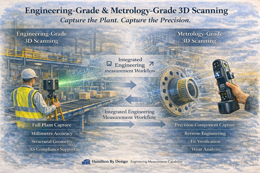
Engineering-grade and metrology-grade 3D scanning in an industrial plant environment.

Choosing the Right Tool for the Right Scale

At Hamilton By Design, we do not approach 3D scanning as a visual service โ€” we approach it as an engineering measurement tool.

Different projects require different levels of accuracy, coverage and control. For this reason, we operate with two distinct scanning capabilities:

  • Engineering-Grade Terrestrial Laser Scanning
  • Metrology-Grade Handheld 3D Scanning

Each serves a specific purpose within industrial, mining and mechanical environments.


Engineering measurement workflow combining plant scanning and precision component capture.

Engineering-Grade 3D Scanning

Capturing Entire Environments with Structural Accuracy

Engineering-grade laser scanning is used when capturing:

  • Processing plants
  • Conveyor systems
  • Structural steel platforms
  • Brownfield facilities
  • Infrastructure corridors
  • Stockpiles
  • Full building interiors and exteriors

This system is tripod-based and captures large-scale environments with millimetre-level accuracy across significant distances.

Typical Performance:

  • Up to hundreds of metres scanning range
  • ~2 mm accuracy at 10 m
  • Full 360ยฐ environmental capture
  • Suitable for survey control alignment

Used For:

  • As-built plant documentation
  • Structural verification
  • Clearance assessments
  • Shutdown planning
  • Retrofit design
  • Compliance validation under AS standards

If you can walk inside it โ€” this is the correct tool.

This system establishes the macro geometry of a site.


Metrology-Grade 3D Scanning

Capturing High-Precision Component Geometry

Metrology-grade handheld scanning is designed for detailed component-level capture.

This system is compact, highly accurate, and capable of sub-0.05 mm precision.

Typical Performance:

  • Accuracy to ~0.020 mm
  • Volume accuracy to 0.015 mm + scale factor
  • Ideal for complex surfaces and confined spaces
  • Suitable for reverse engineering

Used For:

  • Worn chute liners
  • Flanges and bolt patterns
  • Pump housings
  • Lifting lugs
  • Machined components
  • Distorted structural connections
  • Deep hole geometry
  • Fit-up verification prior to fabrication

If you can hold it โ€” this is the correct tool.

This system establishes the micro geometry of a part.


Why Both Matter

Industrial projects often require both levels of capture.

Example: Mining Shutdown

  1. Engineering-grade scanning captures the entire transfer station.
  2. Metrology-grade scanning captures the worn liner plate.
  3. Data is combined to:
    • Verify fit
    • Model replacement components
    • Reduce fabrication risk
    • Avoid rework during shutdown

This integrated approach reduces:

  • Site time
  • Fabrication errors
  • Installation clashes
  • Cost overruns

Measurement With Engineering Intent

We do not scan for visualisation alone.

We scan to support:

  • Structural compliance
  • Mechanical design
  • FEA validation
  • Access verification
  • Brownfield modification
  • Asset documentation
  • Engineering governance

Scanning without engineering oversight introduces risk.

Scanning with engineering intent reduces it.


When To Use Each Scanner

ScenarioEngineering-Grade ScannerMetrology-Grade Scanner
Full plant captureโœ”
Structural steel verificationโœ”
Conveyor alignmentโœ”
Large-area as-built surveyโœ”
Reverse engineering a componentโœ”
Flange or bolt pattern captureโœ”
Wear measurementโœ”
Fabrication fit verificationโœ”
Confined detailed geometryโœ”

Hamilton By Design logo displayed on a blue tilted rectangle with a grey gradient background
3D LiDAR scanning and 3D modelling service button โ€” laser scanner capturing a point cloud for engineering and CAD modelling
Mechanical engineering services

National Capability

Hamilton By Design provides:

  • Engineering-grade terrestrial scanning
  • Metrology-grade handheld scanning
  • Integrated modelling and verification
  • Compliance-aligned documentation

Across mining, industrial and infrastructure environments throughout Australia.


If your project requires both macro capture and micro precision, we can deliver a structured scanning approach aligned with engineering outcomes.


3D CAD Modelling Australia service banner for Hamilton By Design
Australian Drafting logo featuring bold white text reading "Australian Drafting" centred on a blue rounded rectangle background.
Engineering Governance title graphic featuring bold white text reading "Engineering Governance" centred on a blue rounded rectangle background.
Mechanical, Structural & Pipework Drafting service banner by Hamilton By Design featuring white text on a blue background.
Mechanical engineering services
Blue rounded button with the text โ€œSolidWorks Designโ€ in white.
Finite Element Analysis (FEA) engineering simulation button
3D LiDAR Scanning Darwin for engineering surveys, laser scanning, reality capture and point cloud modelling services
3D LiDAR Scanning Australia engineering services for laser scanning, reality capture, scan-to-CAD, Scan-to-BIM and as-built documentation across Australia
3D LiDAR scanning services on the Central Coast providing engineering-grade laser scanning, point cloud capture, scan-to-CAD modelling and industrial reality capture for infrastructure and industrial projects.
3D LiDAR Scanning Perth for engineering surveys, laser scanning, reality capture and point cloud modelling services
3D LiDAR Scanning Sydney for engineering surveys, laser scanning, reality capture and point cloud modelling services
3D LiDAR Scanning Brisbane for engineering surveys, laser scanning, reality capture and point cloud modelling services
3D LiDAR Scanning Canberra for engineering surveys, laser scanning, reality capture and point cloud modelling services
3D LiDAR Scanning Newcastle for engineering surveys, laser scanning, reality capture and point cloud modelling services
3D LiDAR Scanning Adelaide for engineering surveys, laser scanning, reality capture and point cloud modelling services

EinScan vs LiDAR Terrestrial Laser Scanners โ€“ Choosing the Right Tool for Reality Capture

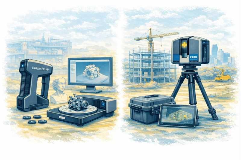
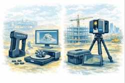
Comparison illustration showing EinScan structured-light scanner on left and FARO LiDAR terrestrial laser scanner on right.

EinScan vs LiDAR Terrestrial Laser Scanners โ€“ Choosing the Right Tool for Reality Capture


The rapid growth of 3D scanning has given engineers, fabricators and designers access to tools that were once limited to large survey companies. Today you can buy a compact EinScan structured-light scanner for a few thousand dollars or hire a FARO or Leica terrestrial LiDAR scanner capable of mapping an entire processing plant in an afternoon. Both are called โ€œ3D scanners,โ€ yet they serve very different purposes. Understanding the difference between EinScan-style scanners and terrestrial LiDAR systems is essential before investing time or money into reality capture.

Two Technologies, Two Different Jobs

EinScan scanners, produced by SHINING 3D, are primarily structured-light or short-range laser scanners. They project patterns of light onto an object and use cameras to interpret how that light deforms across the surface. The result is a dense mesh model of the objectโ€”typically exported as STL, OBJ or PLY files. EinScan units are designed for objects you can walk around, such as mechanical parts, castings, plastic housings and small assemblies.

Terrestrial LiDAR scanners such as the FARO Focus, Leica RTC360 or Trimble X-series operate on a completely different principle. These instruments sit on a tripod and fire millions of laser pulses across a 360-degree field, measuring the time it takes for each pulse to return. The output is a georeferenced point cloud containing precise XYZ coordinates for everything the laser can seeโ€”buildings, structures, conveyors, tanks, pipework and terrain.

Calling both devices โ€œ3D scannersโ€ is like calling a vernier caliper and a total station the same tool. They both measure, but at entirely different scales.


Visual comparison of EinScan object scanner and LiDAR terrestrial laser scanner in matching sketch style.

Scale and Range

The first and most obvious difference is working range.
An EinScan handheld unit is comfortable scanning parts from a few centimetres up to perhaps three or four metres. It is ideal for a gearbox housing on a bench or the plastic bumper of a vehicle. Once the object grows larger than a small room, the scanner begins to lose tracking and accuracy.

A terrestrial LiDAR scanner is built for the opposite end of the spectrum. A FARO Focus S-series can capture data from 0.6 metres out to 70 metres or more, mapping entire buildings or industrial sites from a single setup. Multiple scans are then registered together to create a complete digital twin of a facility.

For workshops and machine shops the question becomes simple:
Are you scanning an object, or are you scanning a place?
Objects suit EinScan; places suit LiDAR.

Accuracy and Tolerance Expectations

Manufacturers often quote impressive numbers, but real-world accuracy must be considered.

  • EinScan desktop and handheld systems typically achieve 0.05โ€“0.2 mm accuracy on small parts when conditions are ideal.
  • Terrestrial LiDAR scanners deliver around ยฑ1 mm to ยฑ3 mm accuracy over distance.

At first glance EinScan appears โ€œmore accurate,โ€ but this is only true at short range. A LiDAR scanner maintains consistent accuracy across tens of metres, something structured-light devices simply cannot do.

For precision mechanical componentsโ€”bearing fits, machined bores, threaded holesโ€”neither technology replaces traditional metrology tools. Scanning excels at capturing shape and context, while micrometers and CMMs remain the authority for tolerance verification.

Type of Data Produced

EinScan produces mesh files made from millions of tiny triangles. These are excellent for visualisation and 3D printing but contain no intelligence about holes, planes or cylinders. CAD systems like SolidWorks or Fusion 360 cannot directly convert these meshes into editable parametric models without additional reverse-engineering work.

LiDAR scanners generate point cloudsโ€”individual points with coordinates and often colour values. Point clouds are perfect for surveying, clash detection, volume calculations and as-built documentation. They are not intended to be edited like CAD models; instead, engineers build new geometry over the top using the cloud as reference.

Understanding this distinction avoids disappointment. Neither scanner delivers a โ€œone-click CAD model.โ€ Human engineering judgement is always required.

Surface and Environmental Limitations

EinScan technology relies on optical cameras and projected light, which introduces several practical limitations:

  • Shiny or black surfaces are difficult to capture
  • Transparent plastics confuse the cameras
  • Deep holes and narrow slots are often missed
  • Sunlight can overpower the projected pattern
  • Tracking can be lost on large flat surfaces

LiDAR systems are more tolerant of environment. They can operate outdoors, in dusty workshops and over long distances. However, they also struggle with highly reflective materials such as polished stainless steel or glass, and they require careful setup to avoid shadows and occlusions.

Workflow Considerations

A typical EinScan workflow looks like this:

  1. Prepare the partโ€”often with scanning spray
  2. Capture multiple passes
  3. Clean and align the mesh
  4. Export STL/OBJ
  5. Rebuild geometry in CAD using the mesh as reference

This process suits reverse engineering of brackets, castings, vehicle parts and consumer products.

A LiDAR workflow is different:

  1. Set up the scanner at multiple locations
  2. Register scans together in software such as FARO Scene or Leica Cyclone
  3. Classify and clean the point cloud
  4. Use the cloud for measurements, modelling or BIM integration

This approach is ideal for as-built surveys, plant upgrades, brownfield design and digital twins.

Cost and Ownership

EinScan systems range from a few thousand to around twenty thousand dollars. They are accessible to small businesses and even serious hobbyists. Software is generally included, and the learning curve is manageable.

Terrestrial LiDAR scanners are capital equipment. Purchase prices often exceed $60,000โ€“$100,000 before software, training and maintenance. For many companies it makes more sense to engage a specialist scanning provider when required.


Hamilton By Design logo displayed on a blue tilted rectangle with a grey gradient background

Choosing the Right Tool

The decision should be driven by the problem you are solving:

Choose EinScan when you need to:

  • Create a bracket to fit an existing motor
  • Reverse engineer a plastic enclosure
  • Modify a vehicle component
  • Capture complex organic shapes
  • Produce meshes for 3D printing

Choose LiDAR when you need to:

  • Document an industrial facility
  • Design around existing plant and pipework
  • Perform clash detection for upgrades
  • Measure volumes and clearances
  • Create a site-wide digital twin

Many organisations ultimately use both. A LiDAR scan provides the big picture, while an EinScan captures detailed components within that environment.

3D LiDAR scanning and 3D modelling service button โ€” laser scanner capturing a point cloud for engineering and CAD modelling
Mechanical engineering services

Integration with CAD

Engineers often ask which scanner works best with SolidWorks or Fusion 360. The honest answer is that neither integrates directly into parametric CAD without intermediate steps. EinScan meshes require reverse-engineering tools or manual modelling. LiDAR point clouds usually pass through Autodesk Recap, FARO Scene or similar before being referenced in CAD.

Scanning is a method of collecting truth, not generating finished design. The value lies in reducing site visits, avoiding clashes and giving designers confidence about existing conditions.

Final Thoughts

EinScan scanners and terrestrial LiDAR systems are not competitors; they are complementary tools on the reality-capture spectrum. One excels at objects on a bench, the other at assets spread across hectares. Selecting the wrong tool leads to frustration, while choosing correctly can transform the way projects are delivered.

For Australian fabricators and engineers, the key question is simple:
Are you capturing a part, or are you capturing a place?
Answer that, and the choice between EinScan and LiDAR becomes clear.

Name
Would you like us to arrange a phone consultation for you?
Address

3D CAD Modelling Australia service banner for Hamilton By Design
Mining & Processing Perth WA banner for Hamilton By Design featuring white text on a blue background.
Scan to BIM Perth WA banner for Hamilton By Design featuring white text on a blue background.
Ship Building Perth WA banner for Hamilton By Design featuring white text on a blue background.
Structural drafting services button
3D LiDAR scanning and 3D modelling services button
Mechanical drafting services button
3D CAD Modelling Australia service banner for Hamilton By Design
3D LiDAR scanning and 3D modelling service button โ€” laser scanner capturing a point cloud for engineering and CAD modelling
Mechanical engineering services
3D CAD Modelling Australia service banner for Hamilton By Design
Mechanical, Structural & Pipework Drafting service banner by Hamilton By Design featuring white text on a blue background.
Australian Drafting logo featuring bold white text reading "Australian Drafting" centred on a blue rounded rectangle background.
Blue banner graphic displaying the text "Point Cloud to CAD - Australia" in large white lettering, representing point cloud processing, scan-to-CAD conversion and digital engineering services across Australia.
CHPP Engineering title graphic featuring bold white text reading "CHPP Engineering" centred on a blue rounded rectangle background.
Engineering Governance title graphic featuring bold white text reading "Engineering Governance" centred on a blue rounded rectangle background.
Mechanical engineering services
Australian Drafting logo featuring bold white text reading "Australian Drafting" centred on a blue rounded rectangle background.
https://www.hamiltonbydesign.com.au/lidar-scanning-brisbane-2
3D LiDAR Scanning Hunter & Newcastle banner with white text on a blue background promoting engineering-grade laser scanning services for industrial, mining and infrastructure projects across the Hunter Valley and Newcastle region.
Mechanical Engineering Hunter & Newcastle banner promoting mechanical engineering services for mining, industrial plants, power generation, manufacturing and heavy industry throughout the Hunter Valley and Newcastle region.
Structural Drafting Hunter & Newcastle banner promoting structural drafting services for mining, industrial plants, power generation, manufacturing and infrastructure projects across the Hunter Valley and Newcastle region.
Mechanical Engineering Perth WA banner for Hamilton By Design featuring white text on a blue background.
3D Laser Scanning Perth WA banner for Hamilton By Design with white text on a blue background.
SolidWorks Perth WA banner for Hamilton By Design featuring white text on a blue background.
Fabrication and product design services
Finite Element Analysis (FEA) engineering simulation button
3D LiDAR scanning and 3D modelling service button โ€” laser scanner capturing a point cloud for engineering and CAD modelling
Blue rounded button with the text โ€œSolidWorks Designโ€ in white.
Mechanical drafting services button
Structural drafting services button

Mechanical Engineering | Structural Engineering