LiDAR Scanning for Industrial Retrofit Engineering | Brownfield Plant As-Built Capture
Steel Mills, Manufacturing Plants & Legacy Facility Upgrades
Across industrial regions such as Pittsburgh, Carnegie and Norristown, engineering teams are not scanning sites for mapping — they are scanning them because they are about to change something critical.
Brownfield facilities rarely match drawings.
Plant modifications fail when decisions are made from assumptions rather than measurements.
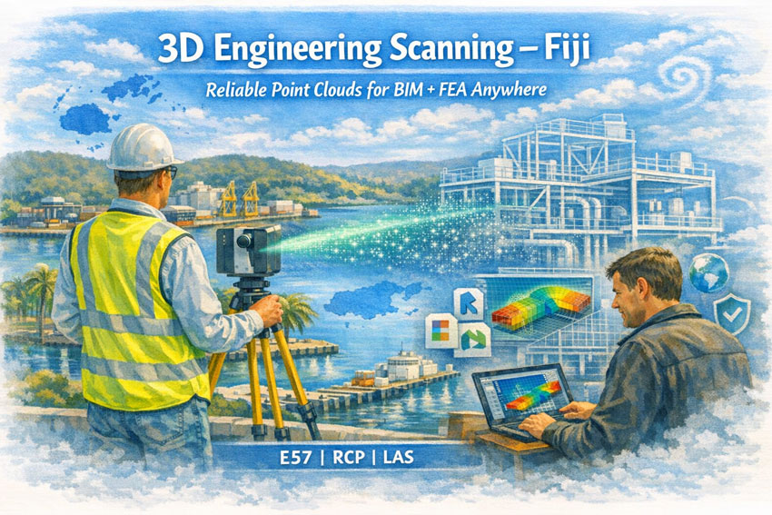
Hamilton By Design provides engineering-grade LiDAR scanning and modelling specifically for retrofit engineering — capturing existing assets so upgrades install correctly the first time.
Why Industrial Facilities Require Scanning Before Design
In heavy industry the problem is rarely design capability — it is uncertainty of the existing plant.
Old facilities typically contain:
- undocumented structural alterations
- relocated services and pipework
- equipment installed over decades
- distorted steelwork
- unavailable or unreliable drawings
When upgrades are designed from historical drawings, fabrication errors and shutdown overruns occur.
Our process replaces assumption with measured reality.
We capture what actually exists — then design from truth.
Hamilton By Design combines mechanical engineering with LiDAR capture to reduce fabrication and installation risk on operating assets.
Typical Projects Supported
Brownfield Industrial Plants
- plant expansions
- conveyor modifications
- structural replacement
- maintenance shutdown preparation
Steel Mills & Heavy Manufacturing
- equipment replacement
- platform and access upgrades
- retrofit guarding & compliance
- mechanical component redesign
Utilities & Processing Facilities
- pipe routing development
- pump and tank replacement
- asset life-extension upgrades
- tie-in engineering
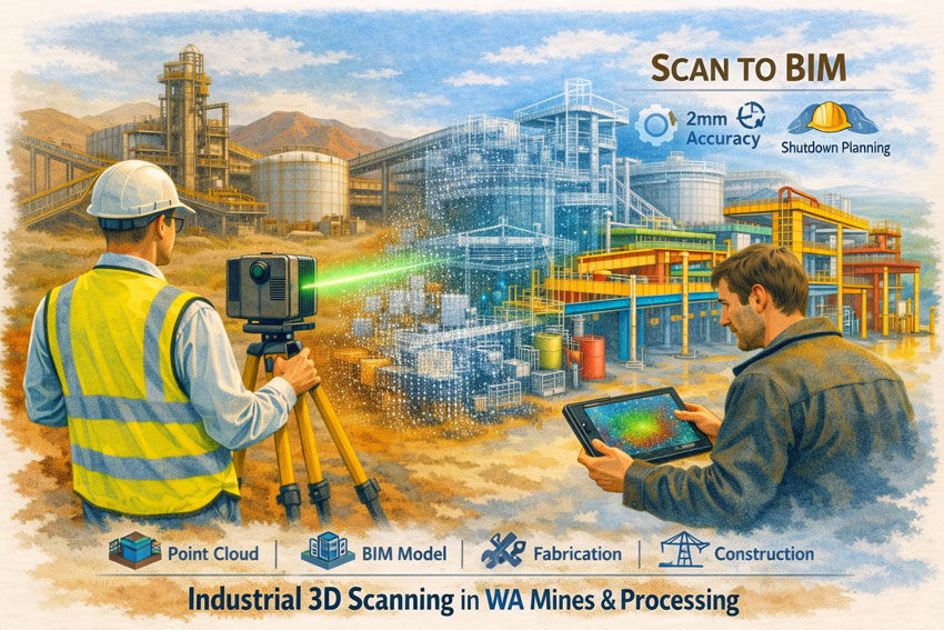
These projects require accurate as-built conditions before design — not survey grade positioning, but engineering-grade dimensional certainty.
Our Retrofit Engineering Workflow
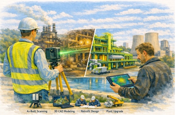
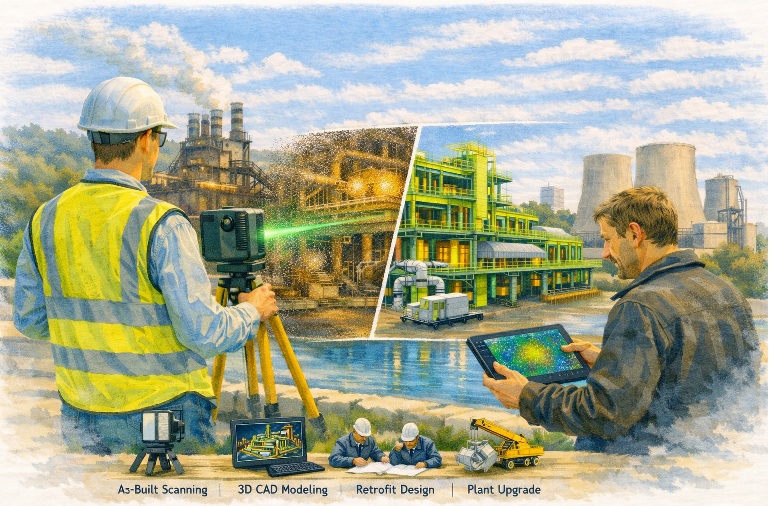
1. Field Capture — Engineering LiDAR Scanning
We capture operating facilities without interrupting production and obtain full spatial reality of structures, equipment and services.
2. Digital As-Built Model
Point cloud data is converted into coordinated 3D engineering models for decision-making and clash prevention.
3. Mechanical & Structural Design
Designs are developed directly from measured geometry rather than historic drawings.
4. Fabrication-Ready Deliverables
We provide models and drawings suitable for fabrication and installation.
This approach allows components to fit existing plant conditions on installation rather than being adjusted in the field.
What This Solves
Industrial retrofit projects fail due to dimensional unknowns — not poor engineering.
LiDAR-driven design removes:
- shutdown delays
- rework fabrication
- on-site modifications
- installation conflicts
- access clashes
Hamilton By Design supports manufacturing, processing and heavy industry with accurate as-built data and coordinated models for upgrades, maintenance and asset life-extension projects.
Engineering-Led Scanning — Not Just Surveying
Many scanning providers supply point clouds.
We provide engineering decisions.
The difference is accountability — one team responsible from measurement to design.
One team accountable from scan to fabrication.
When to Engage Us
Engage scanning early when a project involves:
- replacing equipment
- modifying structure
- adding services
- shutdown installation
- upgrading legacy facilities
If fabrication depends on existing conditions, scanning should precede design — not follow it.

Talk to Hamilton By Design
Hamilton By Design delivers engineering-grade LiDAR scanning and retrofit design support for operating industrial assets worldwide.
Reduce installation risk.
Design from measured reality.