Reverse Engineering Kingsgrove: Turning Existing Machinery into Accurate Engineering Data

Kingsgrove is one of southern Sydney’s established industrial areas. Its combination of food production, packaging machinery, electrical products, automation, plastics, rubber products, fabrication and warehousing creates an ongoing need for practical mechanical engineering support.
Many businesses in the area rely on machinery that has operated for years or even decades. During that time, equipment may have been modified, relocated, repaired or upgraded without the original engineering drawings being revised. Other machines may have been imported without complete documentation, while replacement components may no longer be commercially available.
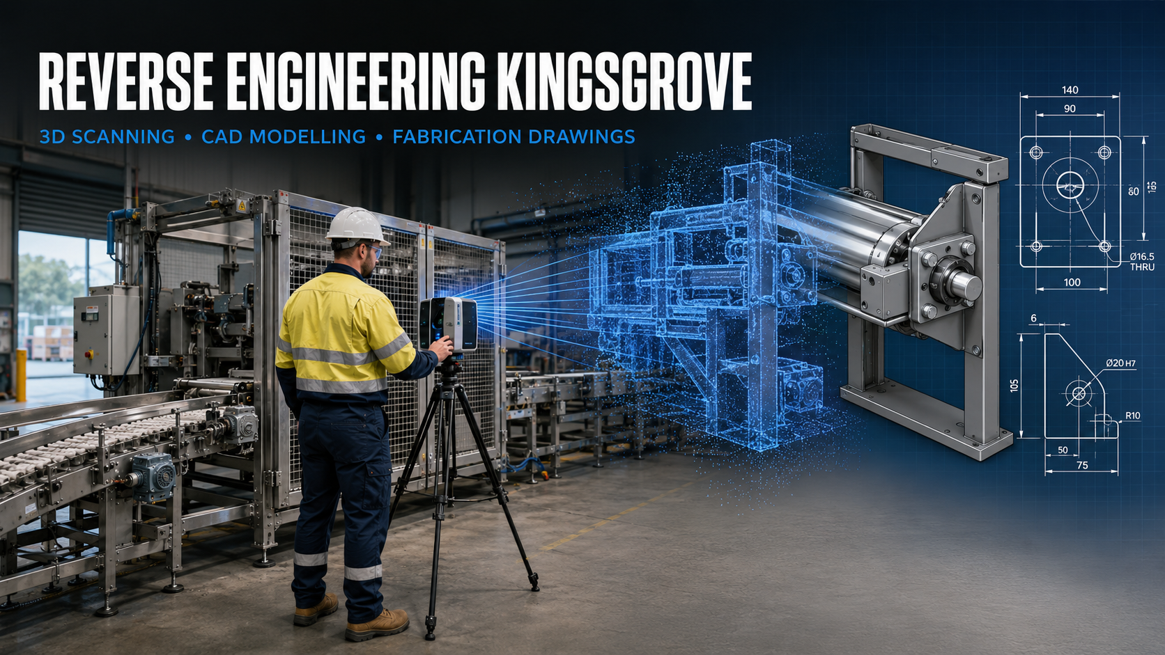
Hamilton By Design provides reverse engineering in Kingsgrove to help manufacturers, machinery suppliers, fabricators and warehouse operators recover this missing engineering information. Through machinery scanning, physical measurement, CAD modelling and engineering assessment, an existing component or machine can be converted into a controlled digital model and a practical set of manufacturing or fabrication drawings.
The objective is not simply to reproduce an object’s external shape. Effective reverse engineering must establish how the component functions, how it connects to surrounding equipment, what loads it may experience and what manufacturing requirements must be communicated.
What Is Reverse Engineering?
Reverse engineering is the structured process of examining an existing component, machine or system to recreate the engineering information required to understand, reproduce, modify or replace it.
The starting point may be:
- An existing machine without drawings
- A worn or damaged component
- An obsolete replacement part
- An imported machine with limited documentation
- A fabricated assembly that has been modified on site
- A production line that no longer matches its original layout
- A component sample supplied to a machine shop
- An incomplete or inaccurate drawing set
Depending on the project, the resulting information may include a 3D CAD model, manufacturing drawing, fabrication drawing, assembly model, general arrangement, factory layout or documented as-built record.
Hamilton By Design combines physical measurement with reverse engineering and Scan-to-CAD studies. This engineering-led approach allows captured geometry to be developed into information that designers, manufacturers, fabricators and maintenance teams can use.
Why Reverse Engineering Is Important in Kingsgrove
Kingsgrove’s industrial businesses often operate in established buildings where production equipment, building services, storage systems and access routes must share a limited amount of space.
A new machine may need to fit between existing columns, conveyors and services. A replacement component may have to connect to equipment manufactured overseas many years ago. A new guard may need to provide safe access without interfering with production or maintenance activities.
Traditional tape measurements and site sketches remain useful, but they can be inefficient when equipment contains complex curves, numerous interfaces or inaccessible features. A small dimensional error can lead to a component that cannot be installed or an assembly that requires modification during a shutdown.
Reverse engineering industrial equipment using 3D scanning provides a more complete record of the existing asset. When combined with critical manual measurements and appropriate engineering checks, scanning can reduce uncertainty and provide a reliable basis for design.
Common Reverse Engineering Problems
Missing or outdated drawings
Machinery is frequently altered during maintenance, repairs or production upgrades. If the drawings are not updated, the documented design gradually becomes different from the physical machine.
Scanning allows the current arrangement to be captured so that new models and drawings represent the actual installed condition rather than an earlier design.
Obsolete replacement parts
Manufacturers may discontinue a component, cease trading or no longer support an older machine. Imported replacement parts may also involve long lead times and significant freight costs.
Reverse engineering can help recreate the dimensional information needed to investigate local manufacture. The component’s material, tolerances, surface finish, heat treatment and operating requirements must still be established before production.
Complex component geometry
Castings, moulded parts, guards, ducts, housings, impellers and worn components may contain shapes that are difficult to define using conventional measurements alone.
A suitable scanner can capture the accessible surface geometry and create a point cloud or mesh from which a controlled CAD model can be developed.
Equipment installation in constrained factories
Production facilities are rarely empty spaces. New machinery must be coordinated with structural columns, electrical services, pipework, conveyors, pedestrian access and maintenance zones.
Hamilton By Design’s engineering services in Sydney can combine existing-condition capture with mechanical design and layout development. This can identify potential clashes before equipment is manufactured or delivered.
Incomplete asset information
Engineering files are often distributed across individual computers, contractors and historical project folders. Point clouds, CAD models and drawings may use inconsistent names or revisions.
A reverse engineering project provides an opportunity to establish a controlled record of the machinery, including the captured data, approved models, fabrication drawings and revision history.
The Reverse Engineering Process
1. Define the engineering purpose
Before scanning begins, the required outcome should be clearly established.
A model intended only for spatial coordination will have different requirements from a component being recreated for precision manufacture. The project should identify:
- The asset or component being investigated
- The reason for reverse engineering
- Required deliverable formats
- Critical interfaces and dimensions
- Expected manufacturing method
- Required accuracy and tolerances
- Material and operating conditions
- Required engineering reviews
Defining these requirements prevents unnecessary modelling and ensures that the selected measurement method is appropriate.
2. Review the existing information
Available drawings, photographs, manuals, spare parts, maintenance records and previous modifications should be reviewed. Even an outdated drawing can provide information about the original material, design intent or nominal dimensions.
The existing equipment should also be discussed with operators and maintenance personnel. Their practical knowledge can reveal recurring failures, access problems, alignment issues and modifications that may not be visible in formal records.
3. Capture the existing asset
Different tools are suited to different types of work.
Terrestrial LiDAR scanning is useful for factories, production lines, building structures and large machinery. Handheld laser or structured-light scanners may be more appropriate for individual components and detailed surface geometry. Precision hand-measurement equipment remains important for bores, shafts, threads, thicknesses, fits and other critical manufacturing features.
Hamilton By Design provides 3D scanning for construction and industrial projects in Sydney, including the capture of existing structures, machinery, plantrooms and equipment interfaces.
The most effective method may combine several measurement technologies rather than relying on a single scanner.
4. Process and verify the captured data
Individual scans may need to be registered into a common coordinate system, cleaned and checked for alignment. Unwanted reflections, temporary objects and inaccessible areas must be identified.
The point cloud or mesh should then be compared with reference measurements. This verification step is important because a visually detailed scan is not automatically suitable for manufacturing.
Measurement uncertainty should be considered in relation to the required fit and function of the component. Where tolerances are tighter than the reliable capture capability, additional metrology may be required.
5. Develop the CAD model
The captured data is used as a geometric reference for creating a practical engineering model. The model may include:
- Individual components
- Parametric features
- Sheet-metal parts
- Weldments and machine frames
- Mechanical assemblies
- Guards and access systems
- Factory or production-line layouts
- Equipment installation envelopes
Hamilton By Design’s Australian design and drafting services support mechanical, structural and industrial projects requiring coordinated models and drawings.
The CAD model should reflect design intent where that intent can be reasonably established. For example, a worn shaft should not necessarily be modelled at its measured worn diameter. The correct nominal size may need to be determined from bearings, seals, mating components, standard fits and operating requirements.
6. Complete the engineering assessment
Reverse engineering becomes particularly valuable when the project moves beyond dimensional copying.
The engineering review may consider:
- Functional requirements
- Material selection
- Manufacturing method
- Dimensional tolerances
- Fits and clearances
- Loads and support conditions
- Wear and corrosion
- Fatigue-sensitive details
- Maintainability and access
- Guarding and machinery hazards
- Interaction with surrounding equipment
Where appropriate, calculations or finite element analysis may be used to compare design alternatives. These assessments must be based on clearly defined loads, boundary conditions and material properties.
7. Prepare manufacturing and fabrication drawings
A 3D model alone may not provide sufficient information for manufacture. Workshop drawings communicate the dimensions, materials, tolerances, welds, finishes and assembly requirements needed to produce the item.
Hamilton By Design provides engineering design and drafting services for industrial equipment, manufacturing facilities and brownfield upgrades.
Depending on the scope, deliverables may include:
- Detailed component drawings
- Fabrication drawings
- General arrangements
- Assembly drawings
- Exploded views
- Bills of materials
- Sheet-metal flat patterns
- DXF cutting files
- Installation drawings
- Controlled PDF drawing sets
- SolidWorks, STEP, DWG or other agreed CAD files
Australian Standards and Engineering Requirements
The relevant Australian Standards depend on the machine, component, industry and intended use. Standards should therefore be selected during the project rather than applied as a generic checklist.
Potential references include:
- The AS 1100 series for technical drawing conventions
- The AS/NZS 4024 series for machinery safety
- AS/NZS 4024.3610 for conveyor systems
- AS 1657 for fixed platforms, walkways, stairs and ladders
- AS 4100 for steel structures
- AS/NZS 1554 for structural steel welding
- AS 4991 for lifting devices
- AS 4084 for steel storage racking
- AS ISO 31000 for risk-management principles
- AS/NZS 3000 where electrical installation requirements are relevant
Preparing a drawing with reference to an Australian Standard does not automatically certify the complete machine or installation. Certification, verification and statutory approval must be specifically included in the project scope and completed by appropriately qualified or licensed people.
Machinery Safety and Guarding
Reverse engineering also creates an opportunity to identify hazards that may have developed through machinery modifications or changing production practices.
Common machinery hazards include:
- Rotating shafts and couplings
- Conveyor nip and drawing-in points
- Crushing and shearing zones
- Unexpected or uncontrolled movement
- Stored pneumatic, hydraulic or mechanical energy
- Ejected components or materials
- Hot surfaces
- Inadequate maintenance access
- Unprotected drive systems
- Unsafe platforms, stairs or access routes
Hamilton By Design provides machine guarding design and engineering for industrial machinery and materials-handling equipment. Assistance may include site capture, guarding assessments, fixed-guard concepts, access arrangements and fabrication drawings.
Guarding should be developed as part of a wider risk-management process. The preferred approach is to eliminate the hazard where reasonably practicable and then consider isolation, engineering controls, administrative controls and personal protective equipment.
Reverse Engineering for Factory and Logistics Operations
Reverse engineering is also useful beyond individual machinery components.
Warehouse and logistics projects may require accurate layouts for conveyors, palletising systems, racking, loading areas, pedestrian routes and mobile equipment. Scanning can document the current arrangement before new equipment is introduced.
For Kingsgrove businesses, possible applications include:
- Production-line modifications
- Conveyor extensions
- Robotic palletising cells
- Equipment relocation
- Warehouse reconfiguration
- Maintenance-access improvements
- Forklift and pedestrian separation
- Platforms and stairs
- Machinery installation planning
- Clash detection
- As-built factory layouts
Accurate spatial information can help designers establish whether new equipment can be delivered, assembled, operated and maintained within the available space.
Retaining Engineering Data for Future Projects
The long-term value of reverse engineering depends on how the resulting information is managed.
Subject to the agreed project arrangements, Hamilton By Design can retain machinery scans, component models, factory layouts, CAD files and fabrication drawings. This can provide a controlled starting point for later repairs, replacement parts, safety improvements or factory modifications.
Good engineering-data management should record:
- Asset identification
- File format
- Model and drawing revision
- Capture date
- Approval status
- Measurement limitations
- Design assumptions
- Related equipment
- Superseded information
This avoids repeating the entire capture process whenever another modification is required.
Frequently Asked Questions
What types of machinery can be reverse engineered?
Hamilton By Design can assess machine frames, guards, conveyors, rollers, shafts, brackets, housings, chutes, hoppers, fabricated assemblies and other mechanical components. Suitability depends on the component’s size, accessibility, complexity and required accuracy.
Can a replacement part be manufactured directly from a 3D scan?
Not always. A scan captures accessible surface geometry, but it does not automatically identify material grade, heat treatment, internal features, design loads, surface finish or manufacturing tolerances. These requirements must be established before a component is released for manufacture.
What if the original component is worn or damaged?
The measured geometry can be compared with mating components, bearings, seals, standard sizes and available historical information. Engineering judgement may then be used to reconstruct the likely nominal geometry instead of simply copying the wear.
Is terrestrial LiDAR accurate enough for every component?
No. Terrestrial LiDAR is highly effective for factories, layouts and large machinery, but precision components may require a handheld scanner, coordinate-measurement equipment or detailed manual measurement. The tool should be selected according to the required tolerance.
Can Hamilton By Design create SolidWorks models?
Yes. Captured data can be converted into SolidWorks parts, assemblies, sheet-metal models and weldments. Other deliverable formats, including STEP, DWG, DXF and PDF, can be discussed during project scoping.
Can existing factory layouts also be captured?
Yes. Machinery scanning can be combined with wider factory capture to document equipment positions, structural interfaces, accessways and surrounding services. This is valuable for equipment relocation, new production lines and brownfield upgrades.
Can reverse engineering assist with machine safety?
Yes. The process can identify exposed moving parts, inadequate guards, restricted access and other design issues. Hamilton By Design can develop guarding and mechanical modification concepts, although formal certification or specialist verification must be included as a defined service where required.
How long does a reverse engineering project take?
The timeframe depends on equipment size, site access, component complexity, required accuracy and the level of drawing detail. A relatively simple component may require only a short capture and modelling process, while a complete machine or production line may require staged scanning, engineering reviews and several drawing packages.
Can the scan data and CAD files be retained?
Yes, subject to the agreed commercial, confidentiality and data-management arrangements. Retaining the files provides a useful engineering record for future maintenance, modification and replacement projects.
Supporting Kingsgrove’s Industrial Businesses
Kingsgrove manufacturers operate in a competitive environment where machinery reliability, production continuity and efficient use of factory space are critical.
Reverse engineering provides a practical way to recover missing information, replace obsolete components, plan equipment modifications and establish accurate engineering records. When scanning is combined with mechanical design, manufacturing knowledge and controlled drafting, the result is more than a digital copy—it becomes a useful engineering resource.
Hamilton By Design provides reverse engineering, 3D scanning, CAD modelling, machinery layouts and fabrication drawings for businesses in Kingsgrove and across Sydney.
Whether the requirement involves a single component, a complete machine or an established factory layout, the process begins by understanding the operational problem and defining the engineering information needed to solve it.

Contact Us – Talk To Us
Our clients: