High Court Changes Engineering Liability

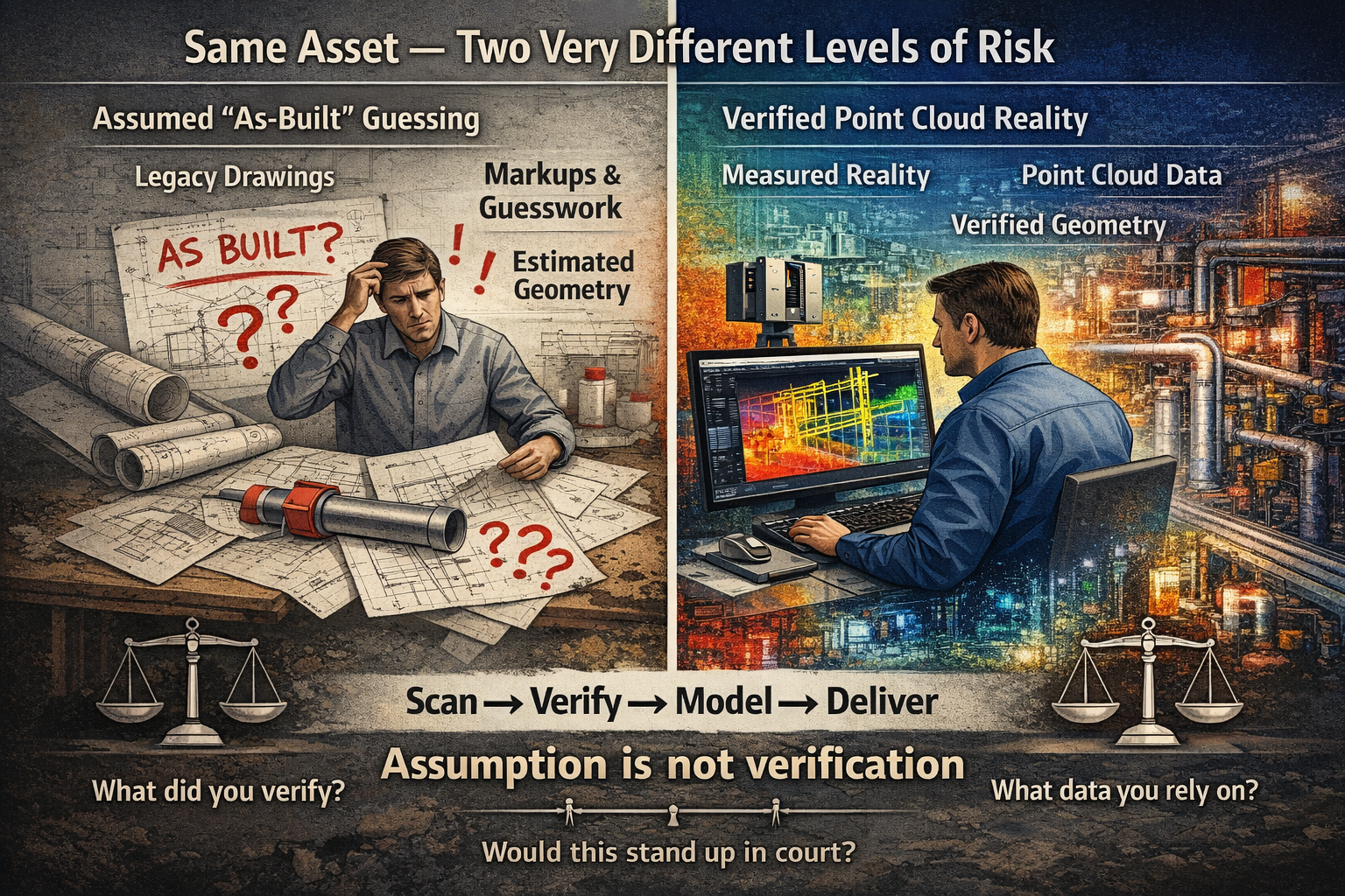
Split-screen engineering graphic comparing assumed as-built drawings with verified point cloud scanning data, highlighting the difference between estimated geometry and measured reality.

The High Court Just Changed Engineering Liability โ€” Why โ€œAs-Built Guessingโ€ Is No Longer Enough

The recent High Court decision in Pafburn Pty Ltd v The Owners โ€“ Strata Plan No 84674 has been widely discussed across the construction and legal sectors. Most commentary has focused on developers and builders, particularly the finding that they can be held fully liable for defects and cannot rely on proportionate liability to distribute responsibility.

But for engineers, designers, and anyone working in brownfield environments, the real impact runs deeper.

This case signals a clear shift in expectation โ€” away from assumption, and toward verified reality.


3D LiDAR scanning and 3D modelling service button โ€” laser scanner capturing a point cloud for engineering and CAD modelling
Mechanical engineering services

The Hidden Risk in โ€œAs-Builtโ€ Drawings

Across many projects, particularly in retrofit, maintenance, and upgrade work, design offices rely on what are commonly referred to as โ€œas-builtโ€ drawings.

In theory, these drawings represent what has actually been constructed on site.

In practice, however, that is not always the case.

Many โ€œas-builtsโ€ are produced through:

  • Manual markups during construction
  • Redline drawings updated after installation
  • Verbal confirmation from site teams
  • Interpretation of incomplete or outdated information

In some cases, they are never formally verified at all.

This creates a fundamental problem.

The design office is making decisions based on information that may be:

  • Incomplete
  • Inaccurate
  • Or in the worst case โ€” assumed

The Question That Is Now Being Asked

Following this High Court decision, the legal environment is changing.

It is no longer sufficient to say:

โ€œI worked from the drawings provided.โ€

Instead, the question is becoming:

What should a competent engineer have verified?

This is a significant shift.

It places responsibility not just on what information was used โ€” but on whether that information should have been trusted in the first place.


Assumption vs Measured Reality

At its core, this issue comes down to a simple comparison:

Does guessing what has been built offer the same level of coverage as measured data?

The answer is increasingly clear โ€” it does not.

When geometry is assumed:

  • Tolerances are unknown
  • Deviations from design are hidden
  • Errors compound as projects progress
  • Rework risk increases

More importantly, from a legal standpoint:

There is no defensible evidence of what actually existed at the time decisions were made.


The Role of Point Cloud Scanning

This is where point cloud scanning and reality capture fundamentally change the workflow.

Rather than relying on interpretation, point cloud data provides a direct measurement of site conditions.

A properly captured scan:

  • Records millions of measured points across the asset
  • Captures geometry exactly as installed
  • Provides a timestamped dataset of site conditions
  • Can be referenced, rechecked, and validated at any time

Most importantly, it creates a feedback loop between site and design.

Instead of guessing what has been built, the design office receives:

  • Accurate geometry
  • Verified spatial relationships
  • Real-world constraints

This allows models and drawings to be developed based on reality, not assumption.


Feeding Reality Back Into the Design Office

One of the most overlooked issues in engineering workflows is the disconnect between site and design.

Information typically flows in one direction:

  • Design โ†’ Construction

But the return flow:

  • Construction โ†’ Design

Is often inconsistent or incomplete.

Point cloud scanning closes this gap.

By scanning installed conditions and feeding that data back into the design environment, engineers can:

  • Align models with actual site geometry
  • Identify clashes before fabrication or installation
  • Validate clearances and fitment
  • Reduce the risk of downstream errors

This is not just about accuracy โ€” it is about confidence.


Why This Matters More After the High Court Decision

The implications of Pafburn Pty Ltd v The Owners โ€“ Strata Plan No 84674 go beyond contractual structures.

They influence how engineering decisions are evaluated.

When something goes wrong, the question is no longer simply:

โ€œWho was responsible for the design?โ€

It becomes:

  • What information was relied upon?
  • Was it reasonable to rely on that information?
  • Could the actual conditions have been verified?

If the tools to verify existed โ€” and were not used โ€” that becomes part of the discussion.


From Design Intent to Verified Condition

The industry is moving through a transition.

Historically, projects were driven by:

  • Design intent
  • Nominal dimensions
  • Idealised geometry

Today, the expectation is shifting toward:

  • Verified condition
  • Measured data
  • Real-world constraints

This shift is particularly important in:

  • Brownfield upgrades
  • Industrial plants
  • Mining infrastructure
  • Retrofit and modification projects

Where existing conditions rarely match original design documentation.


Practical Implications for Engineers

For engineers and designers, this means a change in approach.

Relying solely on drawings โ€” particularly for existing assets โ€” introduces risk.

A more robust workflow includes:

  • Verification of critical geometry
  • Clear documentation of data sources
  • Separation of assumed vs measured information
  • Use of reality capture where accuracy matters

This is not about replacing engineering judgement.

It is about supporting that judgement with evidence.


Conclusion: Coverage, Confidence, and Accountability

At the centre of this discussion is a simple idea:

Not all information offers the same level of coverage.

โ€œAs-builtโ€ drawings based on interpretation provide one level of confidence.

Measured point cloud data provides another.

As legal expectations evolve, the difference between the two becomes more significant.

Guessing what has been built โ€” even when done carefully โ€” does not offer the same level of coverage as data that can be measured, verified, and defended.


How We Approach It

At Hamilton By Design, our workflow is built around this principle:

Scan โ†’ Verify โ†’ Model โ†’ Deliver

By capturing real-world conditions and feeding that data back into the design process, we reduce uncertainty and provide a clear basis for engineering decisions.

Not just for better outcomes โ€” but for greater accountability.


If your next project relies on โ€œas-builtโ€ drawings alone, it is worth asking:

Are they measuredโ€ฆ or assumed?

3D CAD Modelling Australia service banner for Hamilton By Design

Our clients

When You Donโ€™t Trust the Design โ€“ And Donโ€™t Know What Youโ€™re Getting

3D laser scanning Sydney Harbour Bridge and Opera House with point cloud overlay for engineering modelling and design verification

In industrial and mechanical projects, one of the most common โ€” and costly โ€” client concerns is simple:

โ€œI donโ€™t trust the designโ€ฆ and I donโ€™t really know what Iโ€™m going to get.โ€

It usually starts with an existing asset.

  • Old drawings that donโ€™t match reality
  • Missing documentation
  • Modifications made over time
  • Conflicting information between teams

At that point, every decision becomes a risk.


The Real Problem Isnโ€™t the Design โ€” Itโ€™s the Data

Most design issues donโ€™t come from bad engineers.

They come from bad inputs.

If your base information is wrong:

  • Models wonโ€™t fit
  • Steel wonโ€™t align
  • Pipework clashes on install
  • Fabrication needs rework

And suddenly, what looked like a solid design becomes a site problem.


3D LiDAR scanning and 3D modelling service button โ€” laser scanner capturing a point cloud for engineering and CAD modelling
Mechanical engineering services

What Clients Are Actually Searching For

When clients say they donโ€™t trust the design, theyโ€™re usually looking for:

  • point cloud to CAD conversion services
  • reverse engineering services
  • mechanical engineering models
  • engineering-grade verification

What they really mean is:

โ€œI need to know this will fit before I spend money building it.โ€


Step 1: Capture Reality โ€” Not Assumptions

The first step is removing uncertainty completely.

Using engineering-grade LiDAR scanning, you capture the real-world geometry of your asset โ€” not what the drawings say, but what actually exists on site.

This is where most projects go wrong:

  • Assumptions instead of measurements
  • Tape measures instead of full coverage
  • Missed geometry due to line-of-sight limitations

With proper scanning, you get:

  • Full spatial accuracy
  • Complete coverage
  • A true digital representation of your plant

Learn more: https://www.hamiltonbydesign.com.au/home/engineering-services/3d-scanning-sydney/


Step 2: Turn Data Into a Usable Engineering Model

A scan on its own isnโ€™t enough.

You need something your engineers and designers can actually use.

We convert point clouds into:

  • Clean 3D CAD models
  • Plant layouts
  • Mechanical assemblies
  • Structural frameworks

Not meshes. Not visuals.

Engineering models that support real design decisions.

Learn more: https://www.hamiltonbydesign.com.au/


Step 3: Design With Confidence

Once the model reflects reality, engineering becomes predictable again.

Now you can:

  • Design around real constraints
  • Eliminate clashes before site
  • Validate clearances and fitment
  • Reduce risk across the project

Learn more: https://www.hamiltonbydesign.com.au/


Step 4: Deliver Drawings That Actually Work on Site

This is where trust is either confirmed โ€” or lost.

With verified models behind them, drawings become:

  • Accurate
  • Buildable
  • Reliable for fabrication and install

This means:

  • Less rework
  • Faster installs
  • Fewer RFIs
  • Better project outcomes

Learn more: https://www.hamiltonbydesign.com.au/


From Uncertainty to Engineering Confidence

Most providers offer a piece of the puzzle.

  • Scanning only
  • Modelling only
  • Drafting only

The problem is โ€” gaps between those stages create risk.

At Hamilton By Design, we connect the full workflow:

Scan โ†’ Model โ†’ Design โ†’ Fabrication

So youโ€™re not left wondering:

  • Will this fit?
  • Are these drawings right?
  • What happens on site?

Instead, you get:

  • Confidence before fabrication
  • Accuracy before installation
  • Clarity before committing cost

Final Thought

If you donโ€™t trust the design, itโ€™s usually because you donโ€™t trust the data behind it.

Fix the data โ€” and the design follows.


Hamilton By Design
Engineering-led scanning, modelling, and design for real-world results.


Name
Would you like us to arrange a phone consultation for you?
Address

3D CAD Modelling Australia service banner for Hamilton By Design

Mechanical Engineering | Structural Engineering


Chute Blockages and Build-Up in Mining Plants

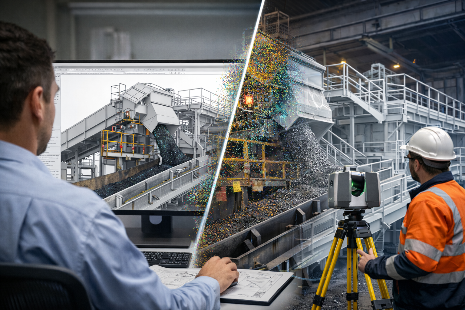
Point cloud mining infrastructure scanning connected to a 3D engineering model of a conveyor transfer chute.

Chute Blockages and Build-Up in Mining Plants | Hamilton By Design Co.

Transfer chute blockages and material build-up are some of the most common and costly problems in mining and bulk materials handling plants. A chute may look simple on paper, but in real operations it must control the flow of difficult materials under changing conditions, often within tight brownfield constraints.

When a chute begins to block, pack up, or accumulate build-up, the result is rarely limited to one small maintenance issue. Restricted flow can lead to reduced plant throughput, unplanned stoppages, excessive wear, spillage, dust, manual clean-outs, and increased shutdown risk.

At Hamilton By Design Co., we use engineering-grade 3D laser scanning, point cloud to CAD modelling, and practical mechanical design workflows to help clients understand why existing transfer chutes are failing and how those problems can be addressed with real-world upgrade solutions.

Why Transfer Chutes Block in Real Plants

A transfer chute does more than direct material from one conveyor to another. It must manage the velocity, direction, confinement, and discharge of a bulk solid that may behave very differently from day to day.

In theory, material should flow cleanly through the chute and load the receiving belt in a controlled manner. In practice, that often does not happen.

Blockages and build-up usually develop because of one or more of the following conditions:

  • Sticky or wet material
  • High fines content
  • Poor internal chute geometry
  • Dead zones or low-velocity regions
  • Sudden changes in direction
  • Inadequate clearances
  • Existing plant modifications not shown on old drawings
  • Wear plates or liners altering the internal flow path over time

This is one of the key lessons from bulk solids handling literature and modern transfer chute simulation work: a chute should be treated as a flow system, not just fabricated steelwork. If the bulk material is not guided correctly, the chute can quickly become the source of recurring reliability issues.

Common Signs of Chute Blockages and Build-Up

Many transfer chutes continue operating badly for months or years before a proper redesign is considered. The warning signs are often already there:

Frequent clean-outs

Operators or maintenance crews may need to manually remove compacted or hung-up material from inside the chute or around discharge points.

Reduced throughput

Partial restriction can reduce the chuteโ€™s effective flow area, limiting plant performance without always producing a full blockage.

Spillage and dust

As the internal flow path changes, material may discharge poorly, generating side loading, skirt leaks, and fugitive dust.

Uneven wear

Material build-up often redirects flow, concentrating abrasion and impact into localised wear zones.

Belt loading problems

A blocked or partially restricted chute can cause off-centre loading, surging, or unstable discharge onto the receiving conveyor.

Shutdown surprises

A chute that โ€œkind of worksโ€ during operation may become a major problem during shutdown replacement or upgrade works when its actual geometry and surrounding interfaces are finally exposed.

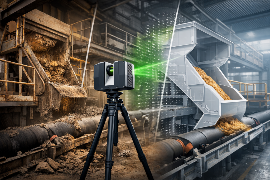
3D laser scanner capturing a blocked mining transfer chute with a digital redesign overlay above a conveyor.

Why Old Drawings Often Do Not Tell the Full Story

One of the most common issues in brownfield mining plants is that the existing chute does not match the drawings.

Over time, sites are modified. Liners are changed. Plates are added. Wear zones are patched. Access platforms are altered. Guards move. Structural members are added or cut back. Conveyor details are updated but not always captured in the plant model.

As a result, a design team can be asked to solve a blockage problem using information that is incomplete, outdated, or simply wrong.

This is where 3D laser scanning of the existing chute and surrounding plant becomes highly valuable. Instead of relying on assumptions, the project can begin with measured site reality.

How 3D Laser Scanning Helps Diagnose Chute Problems

3D laser scanning allows existing transfer stations, chute structures, conveyors, supports, platforms, and surrounding equipment to be captured accurately as an as-built point cloud.

This gives engineers and plant teams a much better starting point for understanding blockage and build-up issues.

With a high-quality site capture, it becomes easier to:

  • Verify the true chute geometry
  • Check whether the internal chute path matches legacy drawings
  • Measure clearances around the chute and conveyors
  • Identify brownfield constraints that will affect upgrades
  • Capture surrounding steelwork, guards, supports, access ways, and services
  • Build a reliable CAD base for redesign or shutdown planning
  • Reduce fit-up risk before fabrication

For blocked or restricted transfer points, this matters because the problem is rarely isolated to one plate or one wear liner. The full transfer arrangement often needs to be understood in context.

Point Cloud to CAD for Chute Upgrade Projects

Once the existing chute and surrounding transfer area have been scanned, the point cloud can be converted into useful engineering models and drawing outputs.

Depending on project requirements, this may include:

  • Existing arrangement models
  • AutoCAD model space layouts
  • General arrangement drawings
  • Section views through critical transfer zones
  • Conveyor interface checks
  • Structural and access reference models
  • Base geometry for redesign concepts

This step is important because scanning alone does not solve the problem. The value comes from turning measured site conditions into a workable engineering model that supports analysis, redesign, communication, and project delivery.

Typical Causes of Chute Build-Up

No two plants are identical, but the same broad patterns appear again and again in mining and bulk materials handling systems.

Poor chute geometry

Flat ledges, abrupt transitions, internal obstructions, and shallow flow surfaces can create low-energy zones where material begins to hang up.

Material variability

A chute may perform reasonably with dry product but fail badly when moisture, fines content, or feed consistency changes.

Wear changing the flow path

As liners wear, the material trajectory and internal contact pattern can change. In some cases, past repairs can unintentionally make the problem worse.

Inadequate discharge control

If the material is not being guided cleanly through the chute, unstable flow can create recirculation, impact concentration, and inconsistent discharge onto the receiving belt.

Brownfield constraints

Legacy chute geometry is often shaped by what could fit at the time, not by what offered the best flow. This is especially true where upgrades have been added over many years.

A Practical Engineering Approach

At Hamilton By Design Co., we see chute blockage problems as both a materials handling issue and a brownfield engineering issue.

That means the practical workflow is often:

1. Capture the existing transfer area

We scan the chute, conveyors, structure, and surrounding plant to create an accurate as-built record.

2. Build the engineering base model

We convert the point cloud into usable CAD references for design, review, and planning.

3. Understand the real constraint

We assess what the current chute is doing, what clearances exist, and where the upgrade risks are likely to sit.

4. Support redesign and upgrade works

The as-built data can then be used to support mechanical design, chute modification concepts, shutdown planning, and fabrication fit-up.

This practical approach is especially useful where the site is already experiencing recurring clean-outs, ongoing maintenance cost, or uncertainty around existing geometry.

Where This Applies

This type of work is relevant across a wide range of bulk materials handling environments, including:

  • Coal handling plants
  • Hard rock mining operations
  • Quarry transfer systems
  • Materials handling conveyors
  • Process plant transfer stations
  • Brownfield chute replacement projects

Why This Matters

Transfer chutes are often underestimated. A poorly performing chute can quietly create lost production, repeated maintenance, high cleanup cost, and shutdown complications for years.

The real lesson from bulk solids handling practice is that a chute should not be designed or upgraded as just a fabricated box. It must be understood as part of a controlled material flow system, operating within the real physical constraints of the plant.

When those constraints are not fully understood, blockage and build-up problems tend to repeat.

That is why 3D laser scanning, point cloud to CAD modelling, and measured as-built engineering data are such valuable first steps in solving restricted or unreliable transfer points.

3D LiDAR scanning and 3D modelling service button โ€” laser scanner capturing a point cloud for engineering and CAD modelling
Mechanical engineering services

Need Support with an Existing Chute Problem?

If your site is dealing with chute blockages, material build-up, inaccurate plant drawings, or shutdown upgrade risk, Hamilton By Design Co. can help capture the existing conditions and provide an engineering-ready base for the next stage of the project.

Hamilton By Design logo displayed on a blue tilted rectangle with a grey gradient background

We support mining and industrial clients with:

  • 3D laser scanning of existing plant
  • Point cloud to CAD conversion
  • Existing condition modelling
  • Brownfield upgrade support
  • Chute and transfer station design workflows

Contact Hamilton By Design Co. to discuss your existing chute, transfer point, or scanning requirement.

Name
Would you like us to arrange a phone consultation for you?
Address

Our clients

CHPP Engineering title graphic featuring bold white text reading "CHPP Engineering" centred on a blue rounded rectangle background.
Pipework Drafting title graphic featuring bold white text reading "Pipework Drafting" centred on a blue rounded rectangle background.
3D LiDAR Scanning for Engineering Projects title graphic featuring bold white text on a blue rounded rectangle background.
3D CAD Modelling Australia service banner for Hamilton By Design

Why Coal Handling Plants Require Accurate Engineering Data

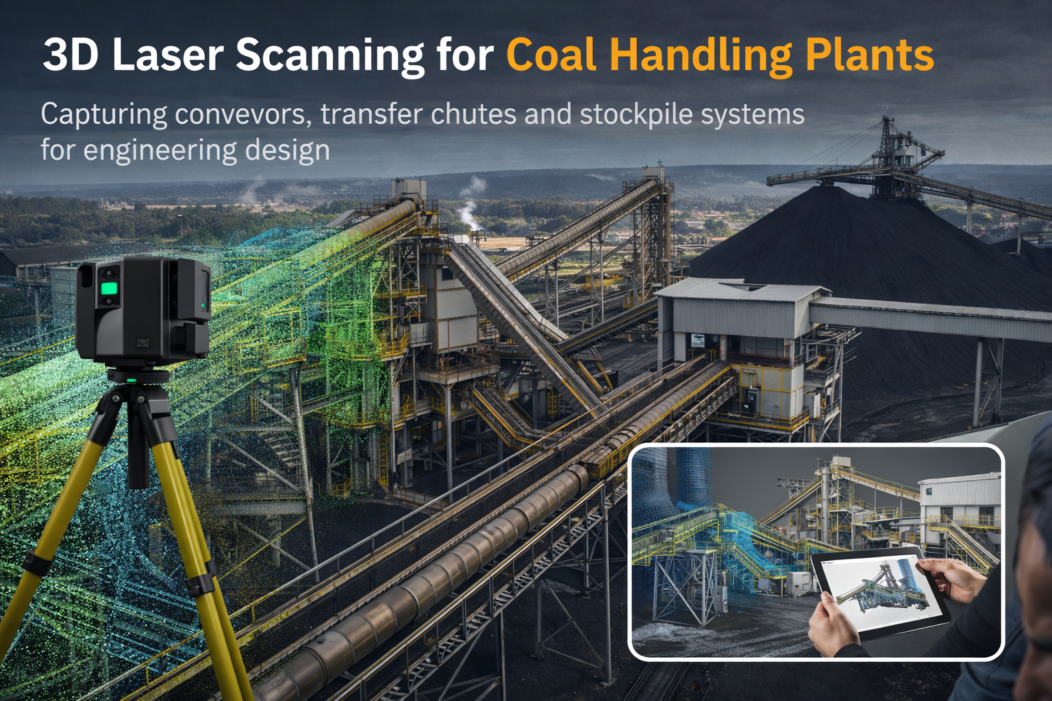
3D laser scanning of coal handling plant conveyors transfer chutes and stockpile systems for engineering design

Coal handling plants are complex facilities designed to move, process, and store large volumes of bulk material. These systems often include:

  • conveyor networks
  • transfer chutes
  • crushers and screens
  • stacker and reclaim systems
  • stockpile infrastructure

Over time, these plants evolve as equipment is upgraded or modified during shutdowns. As a result, original drawings can become outdated or incomplete.

This is where coal handling plant laser scanning becomes an essential engineering tool. By capturing the exact geometry of existing infrastructure, engineers can develop accurate models of the plant before designing modifications or upgrades.


Capturing Existing Plant Infrastructure

3D laser scanning allows engineers to capture millions of measurement points across a facility, creating a highly detailed digital representation of the plant environment.

In coal preparation plants, this technology is particularly valuable for capturing:

  • conveyor structures
  • transfer chute geometry
  • stockpile conveyor systems
  • structural steel frameworks
  • access platforms and walkways

The resulting point cloud provides a precise reference for engineering teams working on plant upgrades, equipment replacements, or shutdown planning.


Scanning Conveyor Systems and Transfer Points

Conveyors are the backbone of most coal handling facilities. They transport coal between crushers, screening plants, stockpiles, and load-out systems.

Transfer points between conveyors are often some of the most complex areas of the plant. Engineers must understand:

  • material flow paths
  • chute geometry
  • clearances around structures
  • maintenance access areas

Using coal handling plant laser scanning, engineers can accurately capture the existing transfer arrangements. This allows them to analyse the system and develop improved designs for:

  • transfer chutes
  • conveyor upgrades
  • dust control systems
  • maintenance access improvements
Accurate digital data significantly reduces the risk of errors when modifying these critical systems.


Capturing Stockpile and Stacker Systems

Coal handling plants typically include large stockpile areas where material is stored before transport or processing.
These systems may include:

  • stacker conveyors
  • reclaim tunnels
  • feeder systems
  • radial stackers

Laser scanning can capture the entire geometry of these systems, including the surrounding structural infrastructure. Engineers can then model the stockpile equipment and evaluate:

  • conveyor alignment
  • discharge geometry
  • reclaim system layout
  • structural clearances

This information is essential when planning equipment upgrades or improving plant reliability.


Creating Digital Engineering Models

Once scanning is complete, the point cloud data can be converted into a digital engineering model of the plant.

These models allow engineers to:

  • design new equipment within existing infrastructure
  • identify clashes before fabrication
  • plan structural modifications
  • improve materials handling systems

Digital plant models are particularly valuable in large facilities where physical measurement would otherwise be difficult or unsafe.

For more information on this approach, see:


Supporting Shutdown Engineering Projects

Many upgrades in coal handling plants occur during planned shutdowns where installation time is limited.

Accurate digital models allow engineering teams to prepare in advance by:

  • confirming equipment fits within existing structures
  • planning installation sequences
  • producing fabrication drawings based on real plant geometry

This preparation helps reduce risk during shutdowns and ensures that new equipment can be installed efficiently.


Improving Reliability in Coal Handling Infrastructure

Coal handling plants rely on complex mechanical systems that must operate continuously to support mining operations.

Using coal handling plant laser scanning provides engineers with a reliable foundation for improving these systems. With accurate digital information, engineering teams can design upgrades that improve:

  • conveyor reliability
  • transfer chute performance
  • maintenance access
  • overall plant efficiency

As mining operations continue to modernise their infrastructure, laser scanning is becoming a key tool for engineers working on bulk materials handling systems.

Name
Would you like us to arrange a phone consultation for you?
Address
CHPP Engineering title graphic featuring bold white text reading "CHPP Engineering" centred on a blue rounded rectangle background.
Pipework Drafting title graphic featuring bold white text reading "Pipework Drafting" centred on a blue rounded rectangle background.
3D LiDAR Scanning for Engineering Projects title graphic featuring bold white text on a blue rounded rectangle background.
3D CAD Modelling Australia service banner for Hamilton By Design
Finite Element Analysis (FEA) engineering simulation button
Mechanical engineering services

Why Pump Skids Are Important in Mining Plants

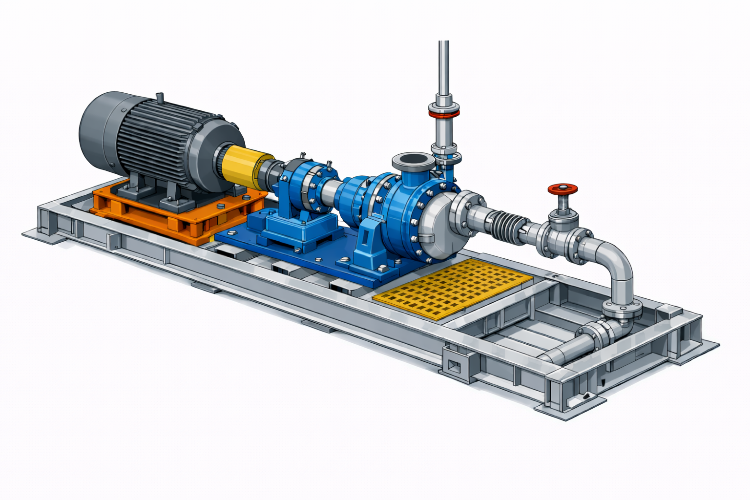
3D engineering model of a mining pump skid with motor, centrifugal pump, piping and structural skid frame

Pump systems are critical components in many mining operations. They are used to move slurry, process water, tailings, and chemicals throughout the plant.

To simplify installation and maintenance, engineers often package pumps and associated equipment into pump skids. A pump skid is a modular assembly that integrates the pump, motor, pipework, valves, instrumentation, and structural base into a single engineered unit.

Effective pump skid design in mining helps operations achieve:

  • faster installation
  • improved equipment reliability
  • easier maintenance access
  • reduced shutdown time

Because mining plants operate continuously, properly engineered pump skids are essential for maintaining plant reliability and operational efficiency.


What Is a Pump Skid?

A pump skid is a pre-engineered mechanical system mounted on a structural steel frame.

Typical components of a mining pump skid include:

  • centrifugal or slurry pump
  • electric motor or drive system
  • suction and discharge pipework
  • isolation and control valves
  • instrumentation and pressure gauges
  • base frame or skid structure

The entire assembly can be transported and installed as a single module, reducing site installation work.


Key Engineering Considerations in Pump Skid Design

Designing pump skids for mining environments requires careful attention to mechanical engineering principles, maintenance access, and operating conditions.

1. Structural Base Frame Design

The base frame must support the pump, motor, and piping loads while maintaining alignment.

Engineers design the skid structure to:

  • support dynamic loads from rotating equipment
  • minimise vibration
  • provide lifting points for transport and installation
  • ensure structural stability during operation

Structural stiffness is particularly important to maintain pump and motor alignment, which directly affects equipment life.


2. Pump and Motor Alignment

Misalignment between the pump and motor can cause:

  • excessive bearing wear
  • vibration issues
  • premature mechanical seal failure

During pump skid design, engineers consider:

  • mounting plate stiffness
  • adjustable motor bases
  • alignment tolerances
  • coupling selection

Accurate alignment is essential for ensuring long-term reliability of rotating equipment.


3. Pipework and Hydraulic Design

The suction and discharge pipework must be carefully designed to avoid performance issues.

Poor pipework design can lead to:

  • cavitation
  • pressure losses
  • vibration
  • premature pump wear

Engineering considerations include:

  • correct pipe sizing
  • smooth flow transitions
  • proper valve selection
  • adequate support for pipework loads

In slurry applications, pipe materials must also be selected to handle abrasive materials common in mining operations.


4. Maintenance Accessibility

Mining maintenance teams must be able to service pumps quickly, particularly during plant shutdowns.

Pump skid layouts should allow:

  • easy removal of pump components
  • access to motors and couplings
  • safe valve operation
  • space for lifting equipment

Maintenance accessibility is a major factor in reducing downtime during shutdown maintenance.


5. Integration With Existing Plant Infrastructure

In many mining facilities, new pump skids must be installed within existing processing plants.

Engineers often use 3D laser scanning and digital plant models to capture the existing environment and ensure the skid fits correctly within available space.

This digital approach helps engineers:

  • identify structural clashes
  • confirm installation clearances
  • verify pipe routing
  • reduce installation risk

More information about mining mechanical engineering design services can be found here:


Designing Pump Skids for Shutdown Installations

Many pump replacements or upgrades occur during planned shutdowns where installation time is limited.

Proper engineering preparation allows pump skid systems to be:

  • fabricated off-site
  • delivered as complete assemblies
  • installed quickly during shutdown windows

This approach significantly reduces the risk of delays during plant maintenance activities.

Learn more about engineering preparation for mining shutdowns here:


Using Digital Engineering to Reduce Installation Risk

Modern mining engineering increasingly relies on digital engineering models.

Using digital plant models allows engineers to:

  • position pump skids accurately within existing infrastructure
  • plan lifting and installation activities
  • verify piping connections before fabrication
  • minimise site modifications

This reduces uncertainty and ensures that equipment fits correctly during installation.

You can read more about this approach here:


Improving Reliability Through Good Equipment Design

Well-designed pump skids improve both equipment performance and plant maintainability.

By integrating mechanical, structural, and piping design into a single engineered assembly, mining operations benefit from:

  • faster equipment installation
  • simplified maintenance procedures
  • improved operational reliability

For mining operations seeking to upgrade plant equipment or install new pumping systems, engineered pump skid design provides a practical and reliable solution for modern processing plants.

Name
Would you like us to arrange a phone consultation for you?
Address
3D CAD Modelling Australia service banner for Hamilton By Design
CHPP Engineering title graphic featuring bold white text reading "CHPP Engineering" centred on a blue rounded rectangle background.
Pipework Drafting title graphic featuring bold white text reading "Pipework Drafting" centred on a blue rounded rectangle background.
3D LiDAR Scanning for Engineering Projects title graphic featuring bold white text on a blue rounded rectangle background.
Finite Element Analysis (FEA) engineering simulation button
Mechanical engineering services

Conveyor Reliability Matters

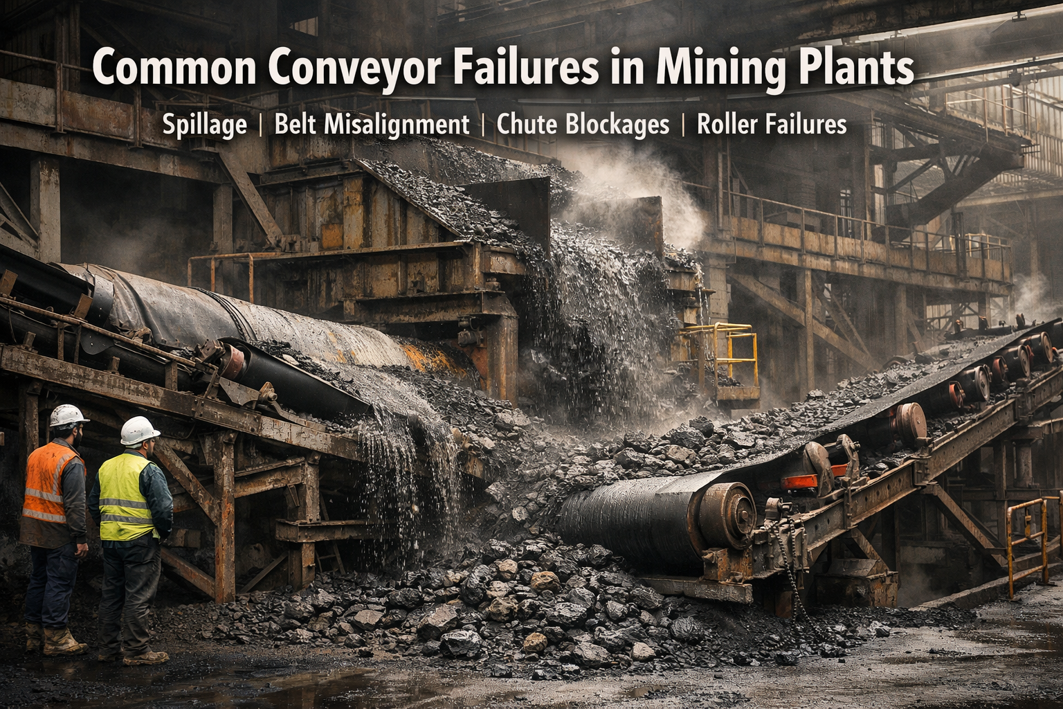
Conveyor system failure in a mining processing plant with spillage and damaged rollers.

Conveyor systems are the backbone of most mining operations. They move thousands of tonnes of ore every hour between crushers, processing plants, stockpiles, and load-out facilities.

When a conveyor fails, the impact can be immediate and costly. Production stops, plant operators must respond quickly, and maintenance teams are forced to work under pressure to restore operations.

Understanding the common causes of conveyor failures in mining plants is essential for improving plant reliability and reducing unplanned downtime.


1. Conveyor Belt Damage

One of the most frequent conveyor failures in mining is damage to the conveyor belt itself.

Typical causes include:

  • impact from large rocks at transfer points
  • sharp materials cutting the belt
  • misaligned loading onto the receiving belt
  • worn or damaged idlers

When belts become damaged, operations may experience:

  • belt tears
  • belt mistracking
  • material spillage

Over time this leads to reduced production efficiency and increased maintenance costs.

Proper chute design and impact control can significantly reduce belt damage.


2. Transfer Chute Blockages

Transfer chutes are often the most problematic areas in materials handling systems.

Poorly designed transfer chutes can cause:

  • material build-up
  • flow restrictions
  • complete blockages

These problems are especially common when handling:

  • wet ore
  • sticky materials
  • fine particles

When chutes block, the upstream conveyors continue feeding material until the system trips or operators intervene.

This can quickly escalate into major plant disruptions.


3. Conveyor Misalignment

Another common maintenance issue is belt misalignment.

Misalignment occurs when the belt does not track correctly along the conveyor structure.

Common causes include:

  • uneven loading at transfer points
  • worn idlers
  • structural movement or damage
  • incorrect installation

When conveyors run out of alignment they can cause:

  • edge damage to belts
  • excessive wear on idlers
  • safety hazards from material spillage

Regular inspection and proper transfer design can reduce this risk.


4. Structural Fatigue and Failure

Mining conveyors operate in harsh environments and are subjected to constant vibration and loading.

Over time this can lead to structural issues such as:

  • cracked steel structures
  • damaged conveyor supports
  • fatigue in transfer chute frames

These failures may not be immediately visible but can develop gradually over years of operation.

Engineering inspections and accurate plant modelling can help identify these risks before they become critical failures.


5. Wear in Materials Handling Equipment

Mining materials are often highly abrasive.

Components that commonly experience heavy wear include:

  • chute liners
  • skirt plates
  • idlers
  • pulley lagging

If these parts are not replaced in time, they can lead to larger system failures.

Preventative maintenance programs help ensure that wear components are replaced before reliability issues develop.


Improving Plant Reliability Through Engineering

Reducing conveyor failures in mining plants requires a combination of:

  • good engineering design
  • proper maintenance practices
  • accurate understanding of existing plant infrastructure

Modern engineering techniques such as 3D laser scanning and digital modelling allow engineers to capture the true geometry of operating plants.

This helps identify problems such as:

  • poor transfer geometry
  • structural clashes
  • restricted maintenance access

These issues can then be addressed before they lead to operational failures.

You can learn more about mining mechanical engineering design services here:


Preparing Conveyor Upgrades During Shutdowns

Many conveyor upgrades and maintenance projects are performed during planned plant shutdowns.

Because shutdown windows are limited, careful preparation is essential.

Engineering preparation may include:

  • capturing existing plant conditions
  • producing detailed engineering models
  • planning structural modifications
  • preparing fabrication drawings

Proper shutdown planning reduces the risk of installation delays and ensures that maintenance work is completed safely.

Learn more about shutdown preparation here:


Using Digital Engineering to Reduce Risk

Digital engineering tools now allow mining operations to develop accurate digital models of their processing plants.

These models help engineers:

  • analyse conveyor systems
  • redesign transfer chutes
  • identify potential failure points
  • plan upgrades with confidence

By using digital engineering models, mining companies can significantly reduce the risk of plant downtime and improve overall reliability.

More information on this approach can be found here:


Final Thoughts

Conveyor systems are critical to the performance of mining plants, but they are also one of the most common sources of operational failure.

By understanding the causes of conveyor failures in mining, operations teams can focus on improving:

  • transfer chute design
  • maintenance practices
  • plant engineering preparation

Through proper engineering and planning, mining companies can improve reliability, reduce downtime, and ensure that their materials handling systems continue to operate safely and efficiently.

3D LiDAR scanning and 3D modelling service button โ€” laser scanner capturing a point cloud for engineering and CAD modelling
Mechanical engineering services
Name
Would you like us to arrange a phone consultation for you?
Address
CHPP Engineering title graphic featuring bold white text reading "CHPP Engineering" centred on a blue rounded rectangle background.
Pipework Drafting title graphic featuring bold white text reading "Pipework Drafting" centred on a blue rounded rectangle background.
3D LiDAR Scanning for Engineering Projects title graphic featuring bold white text on a blue rounded rectangle background.
3D CAD Modelling Australia service banner for Hamilton By Design