Industrial facilities commonly rely on equipment that has operated for many years through upgrades, repairs, and ongoing modifications. Over time, engineering drawings may be lost, equipment may be altered from original configurations, or replacement components may become difficult to source.
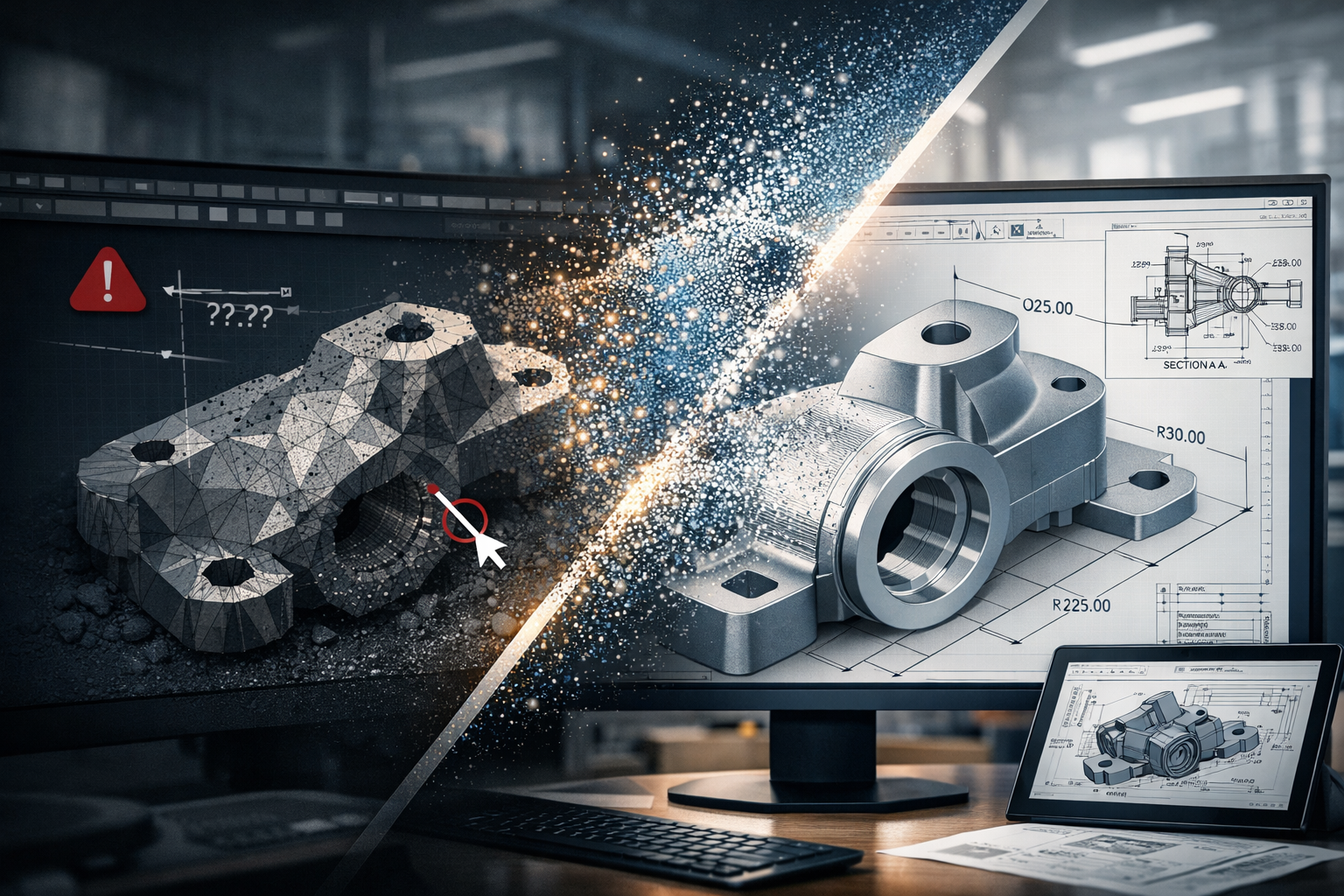
When maintenance teams need to reproduce a component or modify an existing system, the challenge often becomes clear:
“We have the physical component, but we do not have the engineering information.”
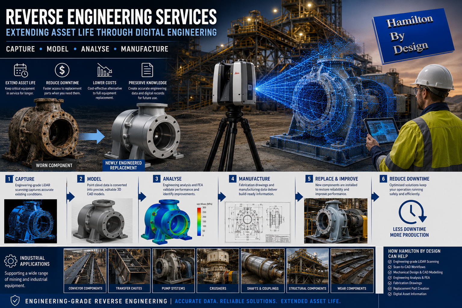
Reverse engineering supported by Scan-to-CAD workflows provides a practical solution by converting physical assets into accurate digital engineering information.
At Hamilton By Design, we combine engineering-grade 3D LiDAR scanning, CAD modelling, and engineering documentation to transform existing components into fabrication-ready deliverables that support maintenance, upgrades, and improved asset management.
What is Scan-to-CAD Reverse Engineering?
Scan-to-CAD reverse engineering involves capturing a physical object or existing asset and converting it into editable engineering models and documentation.
Rather than relying on manual measurements or assumptions, engineering teams can create digital representations based on accurate measured information.
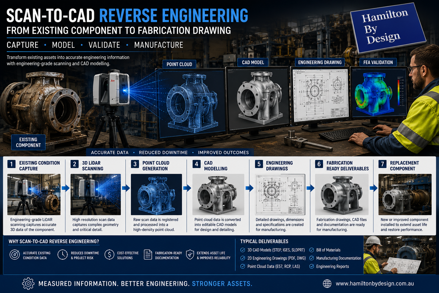
The workflow typically moves through:
Physical Component → Digital Capture → CAD Model → Engineering Documentation → Fabrication
The objective is creating engineering information that can support manufacturing and future asset management.
Existing Condition Capture
Reverse engineering begins with understanding the actual condition of an existing component.
Equipment operating in mining and industrial environments commonly experiences:
- Wear
- Modifications
- Distortion
- Repairs
- Build-up
- Material loss
- Damage
Capturing existing conditions accurately becomes critical.
Typical assets may include:
- Pump components
- Shafts
- Conveyor systems
- Transfer chutes
- Structural components
- Wear liners
- Mechanical assemblies
- Processing equipment
Accurate existing condition capture reduces uncertainty before engineering work begins.


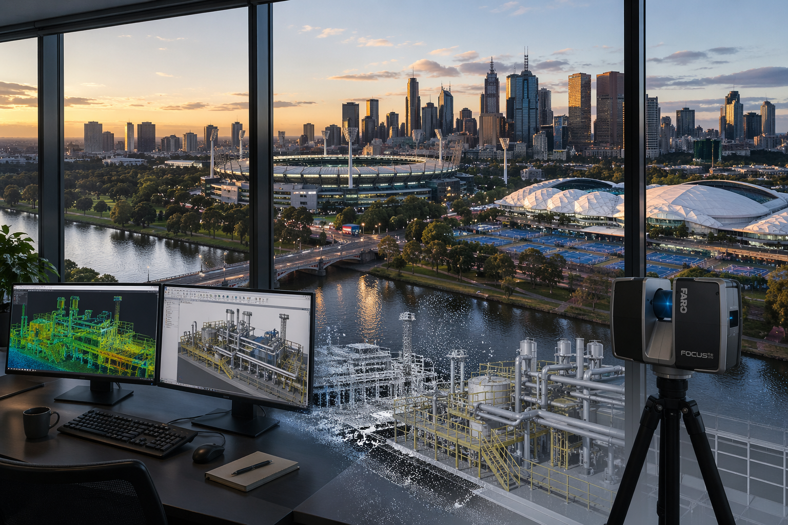
Engineering-Grade 3D LiDAR Scanning
Hamilton By Design uses engineering-grade 3D LiDAR scanning to capture component geometry and surrounding environments.
LiDAR scanning can capture:
- Complex geometry
- Existing plant layouts
- Mechanical equipment
- Structural components
- Dimensional relationships
- Access constraints
Benefits may include:
- Reduced manual measurement requirements
- Improved accuracy
- Faster information capture
- Existing condition verification
- Reduced engineering assumptions
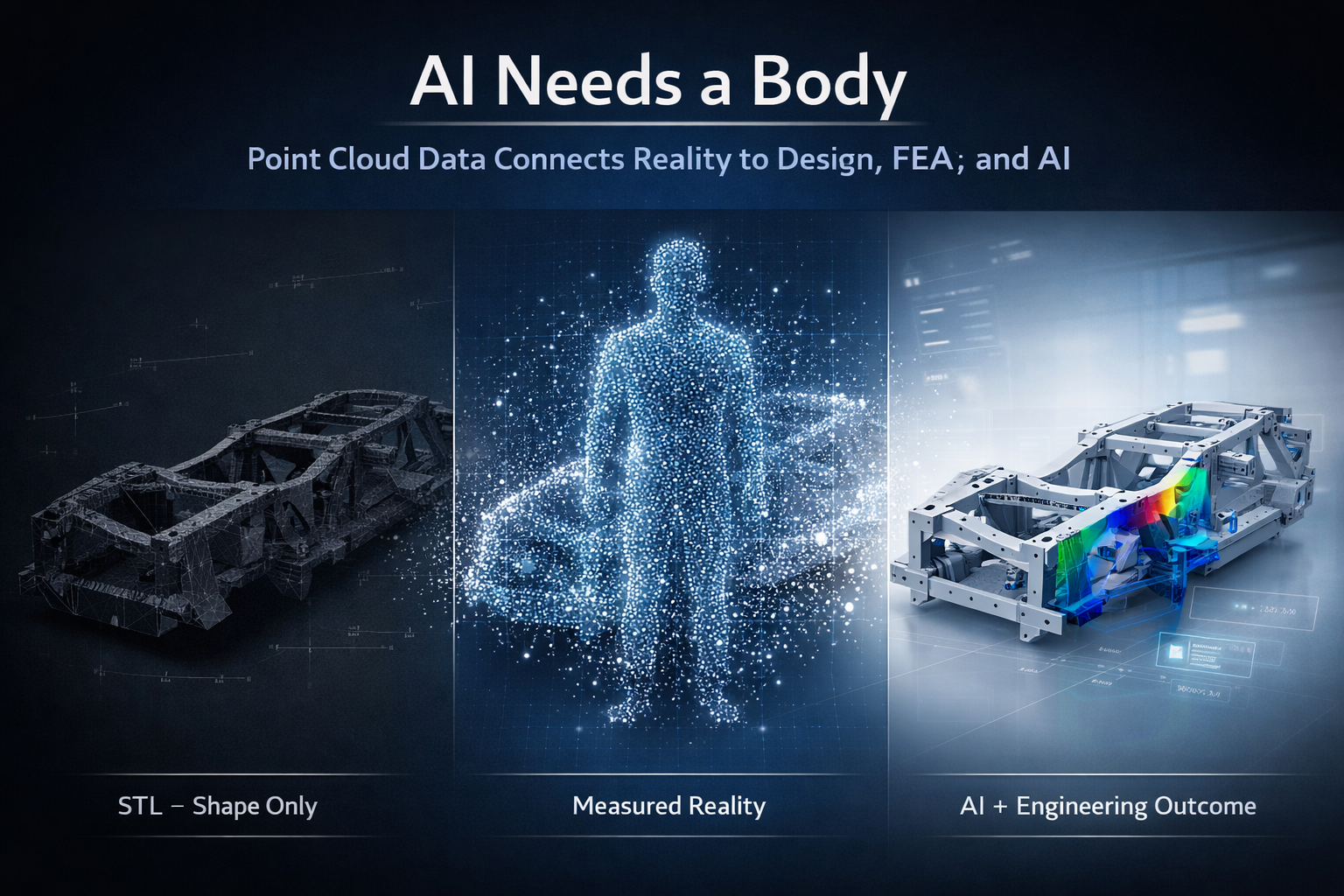
Point Cloud Generation
Following site capture, scan information is processed into a point cloud dataset.
Point clouds provide:
- Measured spatial information
- Existing geometry
- Dimensional verification
- Digital representation of physical assets
Point cloud information becomes the foundation for further engineering development.
Point cloud deliverables may include:
- .E57 files
- .RCP files
- .LAS files
- Registration reports
Rather than relying on estimated dimensions, engineering decisions can be based on measured information.
CAD Modelling
Once point cloud information is generated, components can be converted into editable engineering models.
CAD modelling allows engineers to create:
- Parametric models
- Mechanical assemblies
- Manufacturing geometry
- Equipment layouts
- Design modifications
- Engineering improvements
Benefits include:
- Improved visualisation
- Future design flexibility
- Digital asset information
- Improved project coordination
For reverse engineering projects, editable CAD models become valuable long-term assets.
Engineering Drawings
Digital models can then be transformed into engineering documentation supporting fabrication and manufacturing activities.
Typical outputs include:
- General arrangement drawings
- Detail drawings
- Assembly drawings
- Dimensional drawings
- Manufacturing drawings
- Bills of materials
Documentation provides manufacturing teams with clear information for production.
Fabrication-Ready Deliverables
The final stage involves developing information that supports practical project execution.
Hamilton By Design deliverables may include:
- 3D CAD models
- PDF engineering drawings
- DWG files
- STEP files
- Point cloud datasets
- Manufacturing documentation
- Engineering reports
The goal is delivering information that moves beyond visualisation and becomes usable engineering data.
Why Scan-to-CAD Matters for Reverse Engineering
Without digital engineering workflows, organisations may face:
- Manual measurement errors
- Missing information
- Extended downtime
- Increased fabrication risk
- Higher project costs
- Rework during installation
Scan-to-CAD workflows can improve:
- Accuracy
- Planning
- Asset management
- Fabrication outcomes
- Project confidence
- Long-term equipment support


How Hamilton By Design Supports Reverse Engineering Projects
Hamilton By Design combines practical engineering experience with digital engineering tools including:
- Engineering-grade 3D LiDAR scanning
- Existing condition capture
- Scan-to-CAD workflows
- CAD modelling
- Engineering drawings
- Fabrication documentation
- Reverse engineering services
The objective is not simply reproducing components.
The objective is transforming existing assets into accurate engineering information that supports maintenance, manufacturing, and long-term operational performance.
Measured information creates better engineering outcomes than assumptions.
Our Clients: