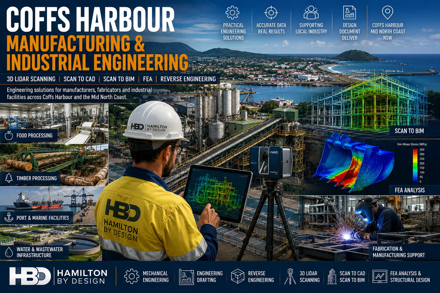
Coffs Harbour Manufacturing & Industrial Engineering
Engineering Solutions for Manufacturers, Fabricators & Industrial Facilities Across the Coffs Coast
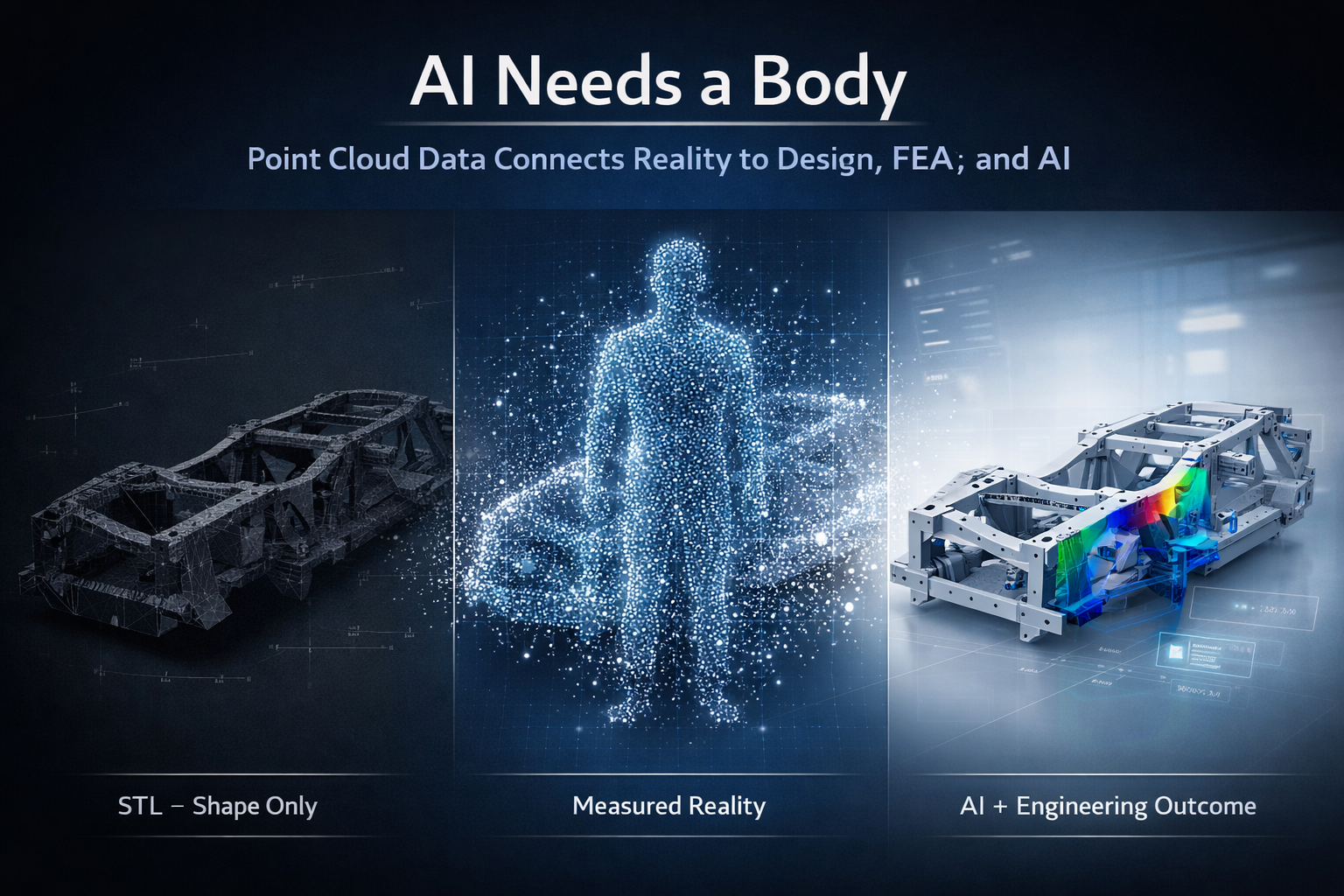
Hamilton By Design provides engineering-led mechanical engineering, 3D LiDAR scanning, Scan to CAD, Scan to BIM, reverse engineering, finite element analysis (FEA) and engineering drafting services throughout Coffs Harbour, Toormina, Sawtell, Woolgoolga, Grafton and the wider North Coast region.
Coffs Harbour is one of regional New South Wales’ most diverse industrial centres, supporting manufacturing, food processing, timber processing, transport infrastructure, marine industries, water utilities and industrial facilities.
As facilities expand and equipment ages, accurate engineering information becomes critical for reducing project risk, improving asset reliability and supporting future growth.
Hamilton By Design helps manufacturers, engineers, fabricators and industrial asset owners capture existing conditions, develop accurate engineering models and deliver practical engineering solutions for both brownfield and greenfield projects.
Engineering Services for Manufacturing & Industry
Supporting Regional Industry Growth
Our services support:
- Manufacturers
- Fabricators
- Timber Processing Facilities
- Food Processing Plants
- Water Utilities
- Industrial Workshops
- Logistics Facilities
- Airport Infrastructure
- Marine Facilities
- Government Infrastructure
Services include:
- Mechanical Engineering
- Engineering Design
- Reverse Engineering
- Engineering Drafting
- FEA Analysis
- 3D LiDAR Scanning
- Scan to CAD
- Scan to BIM
- Asset Documentation
3D LiDAR Scanning Coffs Harbour
Engineering Grade Reality Capture
Hamilton By Design provides engineering-grade terrestrial laser scanning services throughout Coffs Harbour and Northern NSW.
Laser scanning captures highly accurate site information that can be used for:
- Existing Condition Surveys
- Industrial Plant Upgrades
- Manufacturing Facility Modifications
- Structural Steel Modelling
- Pipework Modelling
- Asset Management
- Construction Verification
Applications include:
Food Processing Facilities
Capture production equipment, processing lines, conveyors and services prior to upgrades and expansions.
Timber Processing Facilities
Accurately model sawmills, conveyors, log handling systems and timber processing infrastructure.
Industrial Manufacturing Facilities
Document existing plant conditions for engineering design and construction planning.
Sawmill & Timber Processing Engineering
Supporting Brownfield Upgrades
The North Coast has a strong timber processing industry with facilities often containing decades of modifications and undocumented changes.
Hamilton By Design supports:
- Sawmill Expansions
- Conveyor Upgrades
- Dust Extraction Systems
- Structural Modifications
- Equipment Replacements
- Facility Modernisation Projects
Using 3D LiDAR scanning and engineering modelling, we help reduce project risk and improve fabrication accuracy.
Scan to BIM Services
Building Information Modelling for Existing Assets
Hamilton By Design develops BIM models from laser scan data for:
- Buildings
- Manufacturing Facilities
- Industrial Plants
- Water Infrastructure
- Utilities
- Government Assets
- Airport Infrastructure
- Processing Facilities
Benefits include:
- Improved project coordination
- Reduced design clashes
- Better asset management
- Digital Twin Development
- Enhanced project planning
Finite Element Analysis (FEA)
Engineering Validation Before Fabrication
Hamilton By Design provides FEA services for:
Loader Buckets
- Wear analysis
- Structural assessment
- Reinforcement design
Excavator Buckets
- Impact load analysis
- Structural integrity reviews
Grader Blades
- Ground engagement loading
- Structural performance verification
Chutes & Hoppers
- Material loading analysis
- Wear zone identification
- Structural optimisation
Industrial Structures
- Platforms
- Walkways
- Support frames
- Access systems
Reverse Engineering Services
When drawings are unavailable or outdated, reverse engineering allows valuable engineering information to be recovered.
Applications include:
- Pumps
- Shafts
- Castings
- Conveyor Components
- Machine Components
- Structural Assemblies
- Wear Parts
Deliverables include:
- SolidWorks Models
- STEP Files
- SAT Files
- Manufacturing Drawings
- Fabrication Documentation
Why Choose Hamilton By Design?
Engineering-Led Solutions
We understand how engineering information is used throughout the project lifecycle.
Practical Industry Experience
Supporting:
- Manufacturing
- Timber Processing
- Food Processing
- Utilities
- Infrastructure
- Industrial Facilities
Advanced Technology
Using:
- FARO Focus Laser Scanners
- FARO Orbis
- FARO SCENE
- SolidWorks
- ANSYS
- Autodesk Inventor
- AutoCAD
- Navisworks
Regional NSW Support
Providing engineering services throughout:
- Coffs Harbour
- Sawtell
- Toormina
- Woolgoolga
- Grafton
- Port Macquarie
- Kempsey
- Northern NSW

Talk to Us – Contact Us
Our clients: