


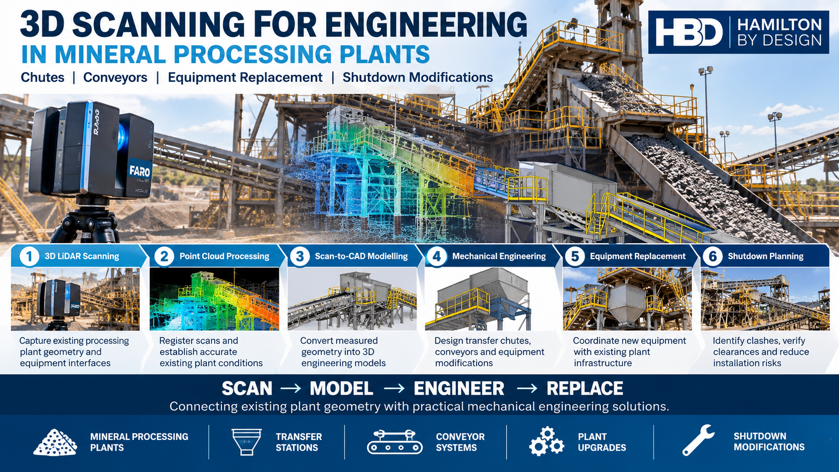
Mineral processing plants operate in demanding environments where equipment wear, structural constraints, material handling requirements and limited shutdown windows can make plant modifications challenging. Replacing a transfer chute, upgrading a conveyor or installing new processing equipment requires more than accurate dimensions. It requires an understanding of how existing equipment, supporting structures and mechanical systems interact.
3D scanning for engineering in mineral processing plants provides a practical way to capture existing plant conditions before mechanical design, equipment replacement and shutdown modifications begin.
At Hamilton By Design, we combine 3D LiDAR scanning, point cloud processing, 3D CAD modelling and mechanical engineering to support mineral processing plant upgrades across Australia.
Our approach connects existing plant geometry with engineering decisions, helping maintenance teams, project engineers and fabrication contractors plan modifications with greater confidence.
Why Accurate Existing Plant Geometry Matters
Mineral processing facilities are continually modified throughout their operating lives. Equipment may be repaired, relocated or replaced, while structural steelwork, platforms, pipework and access arrangements are progressively altered.
Unfortunately, existing engineering drawings do not always reflect these changes.
Common challenges include:
- Transfer chutes that have been modified without updated fabrication drawings.
- Conveyor structures with undocumented changes to supports and equipment interfaces.
- Restricted access around crushers, screens, pumps and processing equipment.
- Pipework and cable trays obstructing proposed replacement equipment.
- Limited opportunities to measure equipment during production.
- Replacement components that must fit within existing structural arrangements.
- Shutdown schedules that leave little time for correcting dimensional errors.
3D LiDAR scanning helps establish a measurable record of existing plant geometry.
Rather than relying exclusively on historical drawings and manual measurements, engineers can reference registered point cloud data when developing replacement equipment and planning modifications.
1. How Is 3D Scanning Used for Engineering Modifications in Mineral Processing Plants?
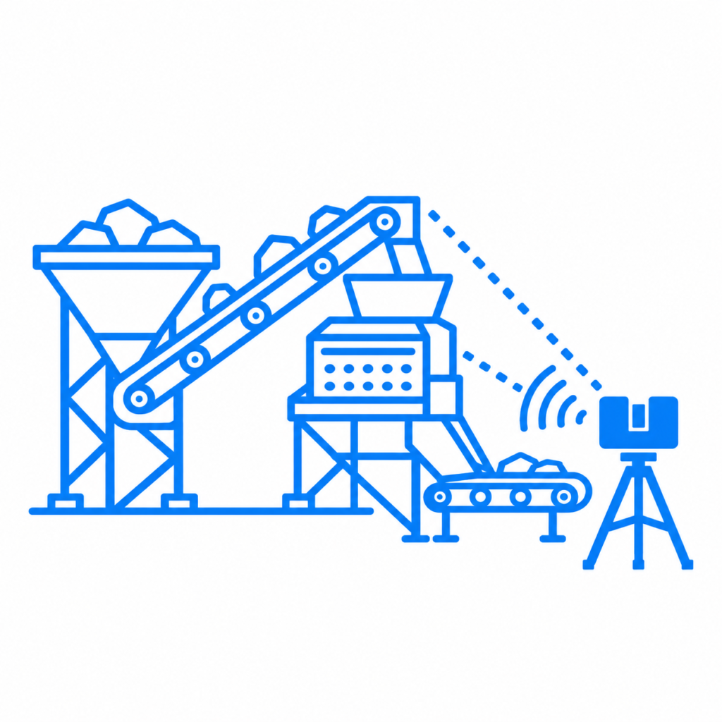
3D scanning captures the visible surfaces of existing equipment, structures and surrounding plant infrastructure.
A terrestrial LiDAR scanner records millions of spatial measurements that can be registered into a coordinated three-dimensional point cloud.
This dataset can then be used to support mechanical engineering and plant modification activities.
Typical engineering applications
| Plant Area | 3D Scanning Application | Engineering Deliverable |
|---|---|---|
| Transfer stations | Capture chute geometry, supporting steelwork and conveyor interfaces | 3D chute models and general arrangement drawings |
| Conveyor systems | Record existing frames, pulley positions and structural clearances | Conveyor modification models and drawings |
| Crushing circuits | Capture surrounding steelwork, access platforms and equipment interfaces | Equipment replacement layouts |
| Screening plants | Measure existing screens, support structures and surrounding services | Equipment installation and modification models |
| Pump installations | Capture pump bases, pipework and equipment connections | Pump skid and pipework arrangement drawings |
| Processing equipment | Identify spatial constraints around existing machinery | Equipment replacement and installation layouts |
| Shutdown modifications | Document existing conditions before shutdown works | Coordinated engineering models and installation planning information |
The resulting point cloud becomes a geometric reference for engineering design.
However, scanning does not replace engineering calculations, equipment specifications or mechanical design verification. These activities remain essential when determining whether proposed modifications are suitable for their intended operating conditions.
2. How Can 3D LiDAR Scanning Improve Chute and Conveyor Replacement?
Transfer chutes and conveyor systems are among the most frequently modified components within mineral processing plants.
These systems experience abrasive wear, impact loading, material accumulation and changing operating requirements.
Replacing a worn transfer chute may appear straightforward, but the new design must integrate with existing equipment and surrounding structures.
Transfer chute engineering
3D LiDAR scanning can capture:
- Existing chute inlet and outlet positions.
- Conveyor discharge and receiving arrangements.
- Structural steelwork and support connections.
- Available space for chute removal and installation.
- Maintenance access and surrounding obstructions.
- Existing flange and equipment interface locations, where accessible.
Point cloud information can then be incorporated into SolidWorks or AutoCAD engineering workflows.
For example, a worn transfer chute may require replacement with a revised geometry intended to improve material flow or reduce maintenance requirements.
The existing plant geometry provides the spatial constraints for the new design.
Additional engineering considerations may include material trajectory, wear liner selection, impact zones, blockage risk, structural loads and maintenance accessibility.
The objective is not simply to reproduce the existing chute, but to develop a replacement that fits the available space and addresses the identified operational requirements.
Conveyor modifications and upgrades
Conveyor replacement projects may involve new pulleys, drive arrangements, transfer points, guarding, access platforms or supporting structures.
3D scanning helps engineers understand the relationship between existing components before modifications are developed.
Typical applications include conveyor frame modifications, drive station upgrades, transfer point changes and structural clearance assessments.
Critical mechanical interfaces still require suitable dimensional verification, particularly where fabrication tolerances are tighter than the achievable accuracy of the registered plant scan.
3. Why Is 3D Scanning Important When Planning Mineral Processing Plant Shutdowns?
Shutdown periods are expensive and operationally sensitive.
Engineering modifications often need to be completed within a limited installation window, with multiple contractors working in the same area.
Unexpected interference between replacement equipment and existing infrastructure can result in additional fabrication, rework and installation delays.
3D scanning supports shutdown preparation by providing engineering teams with a detailed record of accessible existing conditions.
Before the shutdown
Scanning can be undertaken during a planned site visit, subject to safe access and operating conditions.
The resulting dataset allows engineers to develop replacement equipment models, review spatial clearances and identify potential clashes before shutdown activities commence.
During engineering development
Replacement equipment can be modelled within the existing point cloud environment.
Engineers can review proposed installation arrangements against surrounding plant geometry, including structural steelwork, pipework, conveyors and access platforms.
Where appropriate, models can also be incorporated into Navisworks for coordination and clash reviews.
During installation
Pre-shutdown dimensional verification can reduce reliance on last-minute site measurements and help identify potential installation constraints earlier.
This does not eliminate installation risk. Final fit-up remains dependent on measurement quality, fabrication tolerances, site changes, lifting arrangements and construction verification.
Nevertheless, identifying geometric conflicts before mobilisation can improve shutdown readiness.
4. How Does Scan-to-CAD Support Equipment Replacement and Mechanical Engineering?
A point cloud contains spatial measurement data, but it is not automatically a complete engineering model.
Scan-to-CAD is the process of using measured geometry to develop CAD representations suitable for design and engineering activities.
At Hamilton By Design, point cloud information can be processed and referenced in mechanical design software to develop models of existing equipment and proposed modifications.
Typical scan-to-CAD workflow
Stage 1 – Site scanning
Capture the relevant plant area using terrestrial 3D LiDAR scanning, including accessible equipment, structural interfaces and surrounding obstructions.
Stage 2 – Point cloud registration
Register individual scans into a coordinated dataset and review registration quality and coverage.
Stage 3 – Existing condition modelling
Develop CAD representations of the relevant equipment, structures and interfaces.
Stage 4 – Mechanical engineering
Develop proposed replacement equipment or plant modifications using the captured geometry alongside applicable engineering requirements.
Stage 5 – Engineering drawings
Prepare general arrangement drawings, equipment layouts and, where included in the agreed scope, fabrication drawings.
Stage 6 – Design verification
Review critical dimensions, clearances and mechanical interfaces. Where necessary, undertake supplementary measurements or detailed metrology before fabrication.
Typical project deliverables
| Deliverable | Engineering Purpose |
|---|---|
| Registered point cloud (.E57, .RCP) | Existing condition reference |
| 3D CAD model | Equipment geometry and proposed modifications |
| STEP or Parasolid files | CAD exchange and fabrication coordination |
| General arrangement drawings | Overall equipment layout and installation interfaces |
| Fabrication drawings | Manufacture of replacement components |
| Navisworks-compatible model | Plant coordination and spatial clash review |
| Engineering calculations, where scoped | Assessment of loads, structural adequacy and mechanical design requirements |
The required deliverables depend on the project scope, available information and level of engineering verification required.
5. Can 3D Laser Scanning Reduce Installation Risks When Upgrading Mineral Processing Equipment?
3D laser scanning can help reduce geometric uncertainty when upgrading or replacing mineral processing equipment.
This is particularly valuable when new equipment must fit into an established plant with limited space and incomplete documentation.
Consider a replacement transfer chute within an existing conveyor transfer station.
The proposed chute may need to accommodate fixed conveyor positions, existing support steelwork, maintenance platforms and surrounding services.
Without a coordinated record of the existing installation, designers may need to rely on several separate measurements and historical drawings.
A registered point cloud provides a more comprehensive spatial reference for evaluating the proposed arrangement.
Potential benefits include:
- Earlier identification of equipment clashes.
- Improved coordination between engineering and fabrication teams.
- Reduced dependence on incomplete historical drawings.
- Better understanding of maintenance and installation clearances.
- Improved planning for shutdown equipment replacement.
- Fewer avoidable dimensional assumptions during design development.
These benefits depend on the quality of the scan, accessibility of critical interfaces and the engineering verification undertaken.
For high-precision equipment connections, bearing locations, machined surfaces and bolted interfaces, additional measurements may be required.
6. Applications Across Mineral Processing Facilities
3D scanning and mechanical engineering can support a broad range of mineral processing operations.
Coal handling and preparation plants
Coal handling and preparation plants commonly contain extensive conveyor systems, transfer stations, screening equipment and structural platforms.
Potential applications include transfer chute replacement, conveyor modifications, wash plant equipment upgrades and shutdown coordination.
Gold and copper processing plants
Crushing, screening, grinding and flotation circuits often contain tightly integrated equipment, pipework and structural systems.
3D scanning can support equipment replacement planning, pump skid modifications, pipework routing and spatial coordination.
Mineral sands and other processing facilities
Mineral sands processing plants and other bulk materials facilities may require modifications to transfer systems, screening arrangements, hoppers, bins and mechanical handling equipment.
Capturing existing geometry helps engineers assess the available installation envelope before developing replacement components.
7. Engineering Accuracy and Dimensional Verification
Understanding the difference between scanning accuracy and engineering tolerance is essential.
A 3D laser scanner records visible surfaces, but the overall accuracy of a registered point cloud depends on several factors.
These include scanner performance, scan distance, registration quality, surface condition, environmental conditions and the selected coordinate reference system.
For many industrial plant surveys, registered datasets may provide an indicative geometric accuracy in the order of ±5–10 mm, depending on project conditions and survey methodology.
This should not be interpreted as a guaranteed tolerance for every measured feature.
Critical equipment interfaces may require higher-accuracy verification using appropriate measurement methods.
Examples include:
- Machined flange faces.
- Precision shaft and bearing positions.
- Bolt hole centres.
- Equipment mounting interfaces.
- Close-tolerance fabrication connections.
Hamilton By Design can combine plant-scale scanning with targeted dimensional verification where the engineering scope requires it.
The appropriate measurement method should be selected according to the design tolerance and installation risk.
8. From Existing Plant Conditions to Engineered Equipment Replacement
A successful equipment replacement project requires more than a three-dimensional model.
The engineering process must consider the interaction between existing geometry, operational requirements, mechanical loads, material characteristics, maintenance access and fabrication constraints.
For mineral processing plant modifications, this may include:
Existing condition assessment: Understanding the actual arrangement of plant equipment and structures.
Mechanical design: Developing replacement equipment that addresses the intended operating requirements.
Structural and mechanical verification: Assessing relevant loads, connections, supports and equipment performance within the agreed scope.
Fabrication coordination: Producing suitable engineering information for manufacturing and assembly.
Installation planning: Reviewing access, clearances, lifting constraints and potential construction interfaces.
By connecting 3D scanning with mechanical engineering, project teams can move from measurement to a coordinated equipment replacement strategy.
9. Why Engage Hamilton By Design?
Hamilton By Design provides 3D scanning and mechanical engineering services for industrial and mineral processing applications.
Our capabilities include:
- Terrestrial 3D LiDAR scanning and point cloud registration.
- Scan-to-CAD and reverse engineering.
- SolidWorks and AutoCAD mechanical modelling.
- Transfer chute and conveyor modification design.
- Mechanical equipment replacement layouts.
- General arrangement and fabrication drawings.
- Point cloud and model coordination using Navisworks.
- Engineering support for plant upgrades and shutdown modifications.
Our workflow integrates site measurement, modelling and mechanical design, reducing the need to treat these as disconnected activities.
We support projects across New South Wales, Queensland, Victoria, Western Australia and other Australian industrial and mining regions, subject to project requirements and site access.
Frequently Asked Questions
What is 3D scanning used for in mineral processing plants?
3D scanning is used to capture existing plant geometry for equipment replacement, chute and conveyor modifications, engineering modelling and shutdown planning. It helps engineers understand the spatial relationships between existing machinery, structures and services.
Can 3D LiDAR scanning be used to design replacement transfer chutes?
Yes. LiDAR scanning can capture the surrounding plant geometry and accessible chute interfaces. Engineers can use this information to develop replacement chute models, subject to additional mechanical design, material flow assessment and critical dimensional verification.
Can mineral processing equipment be scanned while the plant is operating?
In some circumstances, yes. Scanning may be possible from approved safe locations without stopping the entire plant. However, moving equipment, vibration, dust, restricted visibility and site safety requirements may affect data quality and access. Shutdown access may still be required for concealed or critical interfaces.
Does 3D scanning replace existing engineering drawings?
3D scanning provides a measured record of visible existing conditions and can be used to update or develop engineering models and drawings. It does not automatically establish design intent, hidden details, material specifications or structural capacity.
How can 3D scanning support shutdown planning?
3D scanning allows replacement equipment to be developed and spatially reviewed against existing plant geometry before shutdown works commence. This can help identify potential clashes, installation restrictions and dimensional uncertainties earlier in the project.
What information is needed before scanning a mineral processing plant?
Typical project information includes the equipment or plant area to be scanned, proposed modifications, required deliverables, site access arrangements, target tolerances and project schedule. Existing drawings and equipment specifications are also useful where available.
What CAD files can be produced from a mineral processing plant scan?
Depending on the scope, deliverables may include registered point clouds, SolidWorks models, STEP files, Parasolid files, AutoCAD drawings, general arrangement drawings and fabrication documentation.
Planning a Mineral Processing Plant Modification?
Whether your project involves replacing a worn transfer chute, upgrading a conveyor, modifying a pump installation or preparing for a planned shutdown, understanding the existing plant geometry is an important first step.
Hamilton By Design provides 3D LiDAR scanning, scan-to-CAD modelling and mechanical engineering services to support mineral processing plant modifications and equipment replacement.
Discuss your next mineral processing plant upgrade with Hamilton By Design.
Visit www.hamiltonbydesign.com.au to discuss project requirements, site scanning and engineering deliverables.