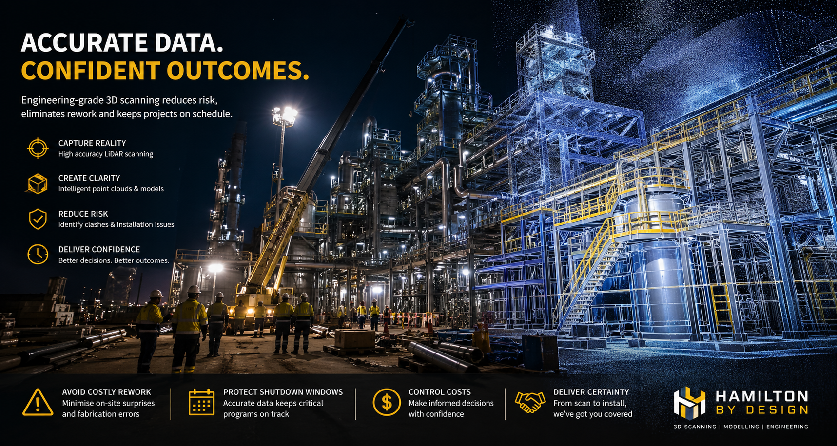
Why Low-Cost 3D Scanning Often Results in Higher Fabrication Costs

Engineering-grade LiDAR scan of an industrial plant showing point cloud and CAD overlay for fabrication accuracy

A Risk-Based Perspective for Project Managers and Company Directors

Executive Summary

The increasing availability of low-cost 3D scanning services has led to a perception that reality capture is a commoditised input to engineering projects. However, within fabrication-driven environmentsโ€”particularly in mining, heavy industry, and brownfield infrastructureโ€”this assumption is fundamentally flawed.

3D scanning is not an isolated deliverable; it is a foundational dataset upon which design, fabrication, and installation decisions are made. When this dataset lacks accuracy, completeness, or governance, downstream impacts emerge in the form of rework, delays, cost overruns, and elevated operational risk.

This paper outlines why low-cost scanning solutions frequently result in higher total project costs and provides a framework for evaluating scanning methodologies from a lifecycle and risk perspective.


1. The Role of Reality Capture in the Project Lifecycle

In modern engineering workflows, 3D scanning underpins a sequence of dependent activities:

  • Site capture (point cloud acquisition)
  • Data registration and validation
  • 3D modelling and design development
  • Detailing for fabrication
  • Installation and commissioning

Each stage inherits the quality of the preceding one. As a result, deficiencies in the initial scan propagate throughout the project lifecycle. Errors introduced at the data capture stage are rarely isolated and are often only fully realised during fabrication or installationโ€”when rectification costs are at their highest.


2. Accuracy as a Determinant of Fabrication Success

Fabrication processes require dimensional certainty. Tolerances associated with structural steel, piping systems, and mechanical assemblies are typically measured in millimetres. Deviations beyond these tolerances can render components unfit for purpose.

Lower-cost scanning methodologies, particularly those relying on unstructured workflows or drift-prone systems, often exhibit:

  • Accumulated positional error over distance
  • Inconsistent alignment between scan sets
  • Limited or absent survey control
  • Reduced reliability in complex industrial environments

While such datasets may appear visually acceptable, they frequently lack the dimensional integrity required for fabrication-grade outputs. The result is misalignment, rework, and increased reliance on site-based modification.


3. Cost Amplification Through Downstream Rework

The primary issue with low-cost scanning is not the initial saving, but the amplification of costs downstream.

A typical failure pathway includes:

  • Design based on inaccurate geometry
  • Fabrication to incorrect specifications
  • Installation conflicts and misalignment

At the installation stage, corrective actions may include:

  • Cutting and re-welding on site
  • Redesign under time constraints
  • Expedited fabrication of replacement components
  • Additional labour and supervision

A relatively small saving in scanning costs can therefore result in significant increases in total project cost, particularly in time-critical environments.



3D CAD Modelling Australia service banner for Hamilton By Design

4. Operational Risk and Downtime Implications

In industrial environments, downtime represents one of the most significant cost drivers. Inaccurate scan data introduces risks that extend beyond fabrication and into operations, including:

  • Extended shutdown durations
  • Delayed commissioning
  • Installation clashes
  • Disruption to production schedules

Given the high cost of downtime in mining and processing facilities, even minor delays can have substantial financial consequences. Low-cost scanning therefore introduces not only technical risk but also operational and commercial risk.


5. Visual Fidelity Versus Engineering Validity

A common misconception is that visually impressive scan data equates to engineering accuracy. Modern software platforms can present dense, colourised point clouds that appear complete and reliable.

However, visual quality does not guarantee:

  • Verified spatial accuracy
  • Consistent coordinate alignment
  • Defined tolerances
  • Reliable integration into engineering workflows

For decision-makers, the critical question is whether the data is demonstrably accurate and suitable for its intended engineering purposeโ€”not whether it appears visually convincing.


6. Data Completeness and Design Integrity

In addition to accuracy, completeness of data capture is essential.

Low-cost scanning approaches often result in incomplete datasets due to time constraints, access limitations, or insufficient planning. Common omissions include:

  • Undersides of structures
  • Connection points and bolt details
  • Congested or hard-to-reach areas
  • Critical interfaces between systems

Incomplete data forces engineers to make assumptions, which introduces uncertainty into the design process. This often leads to conservative design, increased material usage, additional site visits, and iterative revisions.


7. Governance and Traceability

Effective project delivery requires a clear and controlled data environment.

Engineering-grade scanning workflows typically include:

  • Registration reports and validation metrics
  • Defined coordinate systems
  • Version control and data management
  • Traceability from scan to model to drawing

Low-cost scanning services often lack these controls, resulting in:

  • Multiple conflicting datasets
  • Poor coordination between disciplines
  • Limited accountability
  • Increased risk during audits or dispute resolution

Without a single source of truth, project risk increases significantly.


8. Fabrication Constraints and Irreversibility

Fabrication environments operate on precision and adherence to documented design. Workshops do not reinterpret dataโ€”they execute it.

When inaccurate scan data informs fabrication:

  • Errors are embedded in physical components
  • Materials and labour are consumed unnecessarily
  • Corrections become costly and complex

By the time issues are identified, the opportunity for low-cost correction has passed.


9. Reframing the Investment Decision

The evaluation of scanning services should be based on total project cost rather than initial expenditure.

  • Low-cost scanning: lower upfront cost, higher downstream risk
  • Engineering-grade scanning: moderate upfront cost, reduced risk and greater predictability

Given that scanning represents a small proportion of overall project cost, decisions based solely on price are often misaligned with project objectives.


10. A Structured Approach to Risk Mitigation

To reduce risk and improve outcomes, the following approach is recommended:

  • Define accuracy requirements aligned with fabrication tolerances
  • Select appropriate scanning methodologies
  • Implement controlled data acquisition and registration
  • Validate datasets prior to design development
  • Integrate scan data into coordinated modelling workflows
  • Maintain governance and version control throughout the project lifecycle

This ensures that reality capture supports, rather than undermines, project delivery.


Conclusion

Low-cost 3D scanning services may appear cost-effective at the outset, but they frequently result in increased costs, delays, and risk when evaluated across the full project lifecycle.

For project managers and company directors, the critical consideration is the integrity of the data informing engineering decisions. In fabrication-driven environments, accuracy and reliability are essential.

Investment in engineering-grade scanning should therefore be viewed not as an optional expense, but as a risk mitigation strategy that underpins successful project delivery.


To support fabrication certainty and reduce project risk, the following engineering-led services are available:

These services are specifically structured to deliver accurate, validated datasets suitable for engineering design and fabrication.


Ensuring Confidence in Fabrication Data

Where projects involve brownfield modifications, shutdown execution, or critical structural and mechanical installations, the reliability of underlying data is a key determinant of success.

Engineering-grade 3D LiDAR scanning provides a controlled and verifiable foundation for design, reducing uncertainty and enabling informed decision-making throughout the project lifecycle.

At Hamilton By Design, the focus is on delivering fit-for-purpose engineering dataโ€”ensuring that models, drawings, and fabrication outputs align with real-world conditions.


3D LiDAR scanning and 3D modelling service button โ€” laser scanner capturing a point cloud for engineering and CAD modelling
Mechanical engineering services

Independent Review of Existing Scan Data

Where scan data has already been captured, an independent review can be undertaken to assess its suitability for engineering and fabrication use.

This includes evaluation of:

  • Registration quality and alignment integrity
  • Dimensional accuracy relative to project requirements
  • Completeness of captured geometry
  • Suitability for downstream modelling and detailing

This approach provides clarity before further design or fabrication investment is committed.


Hamilton By Design logo displayed on a blue tilted rectangle with a grey gradient background

Contact Us – Talk to Us

For further discussion regarding project requirements or to review an existing scanning approach:

Hamilton By Design
Email: [email protected]
Website: www.hamiltonbydesign.com.au

Enquiries are welcome to arrange a brief discussion to determine the most appropriate approach for achieving reliable, fabrication-ready outcomes.

Name
Would you like us to arrange a phone consultation for you?
Address

Our clients


Mechanical Engineering | Structural Engineering


Brownfield Costโ€“Benefit: Engineering Design vs Continuous Navisworks Model Maintenance

Executive Summary

In brownfield projects, the highest return comes from applying engineering design effort at the point of change, supported by accurate point cloud data, rather than continuously updating a federated model.

The practical reality is:

Invest in engineering decisions, not in maintaining a model that becomes outdated faster than the plant changes.


3D LiDAR scanning and 3D modelling service button โ€” laser scanner capturing a point cloud for engineering and CAD modelling
Mechanical engineering services

Two Approaches

1. Model Maintenanceโ€“Centric (Navisworks)

Using Autodesk Navisworks Manage as an ongoing platform:

  • Maintain a full federated model
  • Update after every site change
  • Re-run coordination and clash detection
  • Manage model alignment across disciplines

2. Engineering-Driven (Point Cloud + Targeted CAD)

Using:

  • FARO SCENE
  • SOLIDWORKS eDrawings
  • Capture and retain point cloud data as the primary asset
  • Model only what is being modified
  • Use CAD and drawings for fabrication and communication

Cost Drivers

Navisworks Model Maintenance

  • Initial model creation and federation
  • Continuous updates after modifications
  • Data conversion and reprocessing
  • Coordination meetings and clash resolution
  • Ongoing QA and model validation

Additional hidden costs include:

  • Model drift corrections
  • Rework due to mismatch with site conditions
  • Reliance on a limited number of trained users

Engineering-Driven Workflow

  • Targeted scanning where required
  • Point cloud processing and validation
  • Engineering design effort for modifications
  • Drawing and component model production

Additional benefits include:

  • Reusable scan data
  • No requirement to maintain a full plant model
  • Faster response to site-driven changes

3D CAD Modelling Australia service banner for Hamilton By Design

Benefit Comparison

Navisworks model maintenance offers strong upfront coordination, particularly in greenfield projects, but suffers from degradation over time and high ongoing cost.

Engineering-driven workflows using point cloud data provide higher long-term accuracy, faster turnaround for small changes, and better alignment with real site conditions.


Line-of-Sight Reality

Point cloud data is inherently line-of-sight dependent. This means:

  • Only visible surfaces are captured
  • Occlusions result in gaps in the dataset

This limitation exists regardless of software platform.

Importing a point cloud into Navisworks does not improve data completeness or accuracy โ€” it simply presents the same data in a different environment.


Practical Example

For a minor electrical upgrade:

Navisworks Approach

  • Update the federated model
  • Re-run coordination
  • Issue revised model
  • Proceed with installation

This introduces significant overhead for a simple task.


Engineering Approach

  • Review point cloud or site conditions
  • Confirm clearances
  • Design locally
  • Install
  • Update drawings if required

This approach is faster, lower cost, and aligned with how work is actually executed.


Where Navisworks Adds Value

Navisworks remains effective when:

  • Multiple disciplines are designing simultaneously
  • Large-scale coordination is required
  • Clash detection is critical

This typically applies to:

  • Greenfield projects
  • Major brownfield upgrades

It should be treated as a project-phase coordination tool, not a long-term data management system.


  • Use point cloud data as the primary reference
  • Maintain raw and registered datasets (e.g. E57)
  • Model only critical interfaces and new work
  • Use drawings for formal deliverables
  • Apply Navisworks selectively where coordination is required

Final Position

In brownfield environments, value is created through engineering design and decision-making, not through continuous model maintenance.


One-Line Summary

Design what youโ€™re changing. Scan what youโ€™re keeping. Donโ€™t model what you wonโ€™t maintain.

Our clients
Talk to Us – Contact Us

Name
Would you like us to arrange a phone consultation for you?
Address
CHPP Engineering title graphic featuring bold white text reading "CHPP Engineering" centred on a blue rounded rectangle background.
Pipework Drafting title graphic featuring bold white text reading "Pipework Drafting" centred on a blue rounded rectangle background.
3D LiDAR Scanning for Engineering Projects title graphic featuring bold white text on a blue rounded rectangle background.

3D Scanning Critical for Design

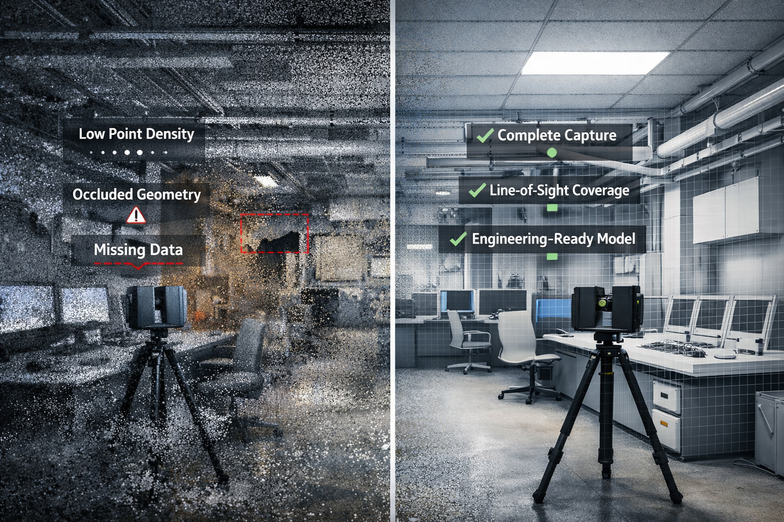
Comparison of poor vs high-quality 3D laser scanning showing missing geometry and complete point cloud data in an industrial workspace

Not All Point Clouds Are Created Equal

3D laser scanning is now widely used across construction, mining, and industrial projects.

But thereโ€™s a major issue we see repeatedly:

The scan is completed โ€” but itโ€™s not usable for engineering.

At first glance, a point cloud can look impressive. Millions of points, full colour, seemingly detailed.

But when it comes time to actually use that data for designโ€ฆ

๐Ÿ‘‰ The gaps start to show.


โš ๏ธ The Problem: Low-Quality Scanning

Many scans are undertaken:

  • Without understanding how the data will be used
  • Using lower-grade equipment
  • With insufficient scan positions
  • Without capturing critical working areas

The result:

  • Missing geometry
  • Low point density
  • Occluded or hidden areas
  • Incomplete or distorted surfaces

In one recent project, we identified areas where:

  • The geometry was not fully captured
  • Point density was low or non-existent
  • Line-of-sight constraints prevented full coverage

๐Ÿ” Why This Matters

A point cloud is not the final deliverable โ€” it is the foundation.

And if that foundation is wrong:

  • CAD models become inaccurate
  • Engineering decisions are based on assumptions
  • Design risks increase
  • Rework becomes likely

You canโ€™t build a reliable design on incomplete data.


๐Ÿ’ก The Difference: Engineer-Led Scanning

At Hamilton By Design, scanning is not just data capture.

It is:
๐Ÿ‘‰ An engineering process

We approach every scan with the end use in mind.


๐Ÿ—๏ธ What Engineer-Led Scanning Looks Like

1. Understanding the End Goal

Before scanning begins, we define:

  • What the model will be used for
  • Required level of detail
  • Critical areas that must be captured

2. Planning Scan Positions

We ensure:

  • Full coverage of all key geometry
  • Minimal occlusions
  • Adequate point density for modelling

3. Capturing Complete Geometry

We focus on:

  • Line-of-sight access between scanner and surfaces
  • Eliminating blind spots
  • Capturing real working areas โ€” not just open space

4. Validating the Data

Before modelling begins, we:

  • Review scan coverage
  • Identify missing or weak areas
  • Confirm the dataset is fit for purpose

โš™๏ธ Why This Matters for Downstream Design

Engineering workflows rely on accurate geometry.

For example, in lighting design using AGi32:

  • Walls influence light reflection
  • Equipment creates shadowing
  • Layout impacts visibility

If these elements are missing or incorrect:

๐Ÿ‘‰ The design outcome will be wrong.


๐Ÿ”„ The True Cost of Poor Scanning

Low-quality scanning often leads to:

  • Time lost rebuilding missing geometry
  • Engineering assumptions instead of real data
  • Incorrect design decisions
  • Additional site visits
  • Project delays and rework

What appears cheaper upfront often becomes significantly more expensive later.


โœ… The Value of Getting It Right the First Time

Engineer-led scanning delivers:

  • Accurate, complete datasets
  • Faster modelling workflows
  • Reliable design outcomes
  • Reduced project risk

It ensures the data is not just captured โ€” but usable.


๐Ÿš€ Where Hamilton By Design Adds Value

We bridge the gap between:
๐Ÿ‘‰ Reality (scan data)
๐Ÿ‘‰ Engineering (CAD models)
๐Ÿ‘‰ Design outcomes

Our capability includes:

  • Engineering-grade 3D laser scanning
  • Point cloud to CAD modelling
  • Scan-to-design workflows
  • Support for industrial, infrastructure, and plant projects

3D LiDAR scanning and 3D modelling service button โ€” laser scanner capturing a point cloud for engineering and CAD modelling
Mechanical engineering services

๐Ÿ“Œ Final Thought

3D scanning is only valuable if it supports accurate engineering decisions.

A scan is not just data โ€” itโ€™s the foundation of your entire project.

And that foundation needs to be right.


Hamilton By Design logo displayed on a blue tilted rectangle with a grey gradient background

๐Ÿ“ž Need Reliable Scan Data?

If youโ€™re:

  • Planning a project
  • Working with poor-quality point clouds
  • Or want to avoid costly rework

We can help ensure your data โ€” and your design โ€” are right from the start.

๐Ÿ‘‰ https://www.hamiltonbydesign.com.au
๐Ÿ‘‰ Get in touch to discuss your project

Name
Would you like us to arrange a phone consultation for you?
Address
3D CAD Modelling Australia service banner for Hamilton By Design
Australian Drafting logo featuring bold white text reading "Australian Drafting" centred on a blue rounded rectangle background.
Engineering Governance title graphic featuring bold white text reading "Engineering Governance" centred on a blue rounded rectangle background.
Mechanical, Structural & Pipework Drafting service banner by Hamilton By Design featuring white text on a blue background.
Mechanical engineering services
Blue rounded button with the text โ€œSolidWorks Designโ€ in white.
Finite Element Analysis (FEA) engineering simulation button
3D LiDAR Scanning Darwin for engineering surveys, laser scanning, reality capture and point cloud modelling services
3D LiDAR Scanning Australia engineering services for laser scanning, reality capture, scan-to-CAD, Scan-to-BIM and as-built documentation across Australia
3D LiDAR scanning services on the Central Coast providing engineering-grade laser scanning, point cloud capture, scan-to-CAD modelling and industrial reality capture for infrastructure and industrial projects.
3D LiDAR Scanning Perth for engineering surveys, laser scanning, reality capture and point cloud modelling services
3D LiDAR Scanning Sydney for engineering surveys, laser scanning, reality capture and point cloud modelling services
3D LiDAR Scanning Brisbane for engineering surveys, laser scanning, reality capture and point cloud modelling services
3D LiDAR Scanning Canberra for engineering surveys, laser scanning, reality capture and point cloud modelling services
3D LiDAR Scanning Newcastle for engineering surveys, laser scanning, reality capture and point cloud modelling services
3D LiDAR Scanning Adelaide for engineering surveys, laser scanning, reality capture and point cloud modelling services

Point Cloud to Engineering Model for Mining Infrastructure

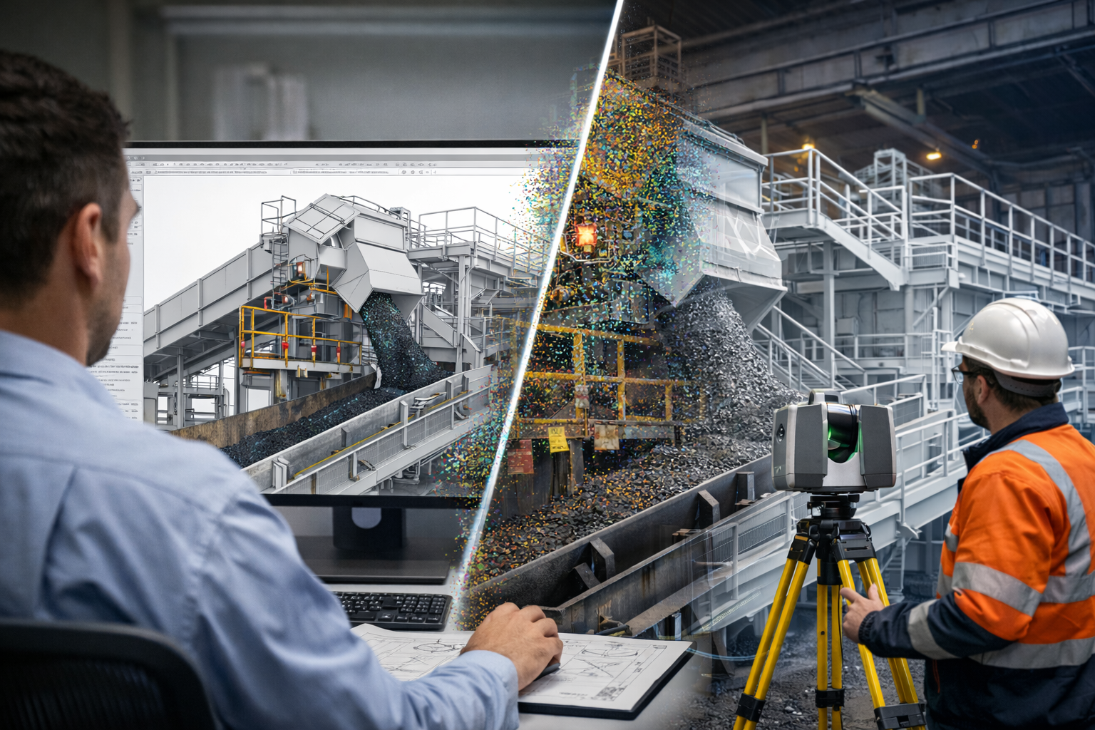
Point cloud mining infrastructure scanning connected to a 3D engineering model of a conveyor transfer chute.

Point Cloud to Engineering Model for Mining Infrastructure

Modern mining infrastructure is complex, constantly evolving, and rarely matches the original construction drawings. Over decades of plant upgrades, maintenance work, and operational modifications, the physical layout of conveyors, chutes, platforms, and structural steel often diverges significantly from historical design documentation.

For engineering teams planning plant upgrades or shutdown work, accurate site information is essential. One of the most effective ways to capture this information is through laser scanning and point cloud modelling, which allows engineers to convert real-world infrastructure into detailed digital engineering models.

The process of converting point cloud mining infrastructure data into engineering models is now widely used across the mining and bulk materials handling industries.


What Is a Point Cloud in Mining Infrastructure?

A point cloud is a dense collection of spatial measurements captured using 3D laser scanning equipment. Each point represents a precise location in space, allowing engineers to reconstruct the geometry of plant infrastructure with extremely high accuracy.

When scanning a mining facility, the point cloud may capture:

  • Conveyors and transfer stations
  • Structural steel platforms and walkways
  • Crushers, screens and processing equipment
  • Stockpile reclaim systems
  • Pipework and mechanical installations
  • Port and ship loading infrastructure

These datasets can contain millions or even billions of measurement points, forming a highly accurate digital representation of the plant environment.


Converting Point Clouds into Engineering Models

While point clouds provide valuable measurement data, they are not directly usable for engineering design. Engineers must convert the scan data into structured mechanical and structural models that can be used for analysis, fabrication and construction planning.

The typical engineering workflow includes:

1. Site Laser Scanning

The plant is scanned using high-accuracy laser scanning equipment to capture the geometry of existing infrastructure.

2. Point Cloud Processing

The raw scan data is registered and combined to form a unified point cloud representing the entire plant area.

3. Engineering Modelling

Engineers interpret the point cloud and convert key infrastructure elements into CAD models including:

  • Structural steel frameworks
  • Conveyor structures and galleries
  • Transfer chutes
  • Access platforms and walkways
  • Mechanical equipment interfaces

4. Engineering Design and Upgrades

The resulting model allows engineers to design plant modifications with confidence, ensuring equipment fits correctly within the existing infrastructure.

This workflow significantly reduces installation risk during shutdowns and upgrade projects.

For further information on mechanical engineering services for mining plants see:


Supporting Shutdown Planning and Plant Upgrades

Mining plants frequently undergo upgrades to improve reliability, throughput and maintenance access. Many of these upgrades are installed during planned shutdowns where downtime must be carefully controlled.

By developing accurate engineering models from point cloud data, engineers can:

  • Confirm clearances for new equipment
  • Identify potential clashes before fabrication
  • Design replacement transfer chutes and conveyors
  • Validate structural modifications
  • Improve maintenance access systems

These digital engineering models are particularly valuable for shutdown preparation.

More information about this process can be found here:


Transfer Chutes and Materials Handling Infrastructure

Transfer chutes are one of the most common areas requiring modification in coal handling plants and mining infrastructure. Poorly designed chutes can lead to excessive belt wear, blockages, dust generation and maintenance challenges.

Using point cloud models, engineers can analyse the surrounding infrastructure and design improved chute geometries that integrate correctly with existing conveyors and structures.

Learn more about chute engineering and materials handling design here:
โžก https://www.hamiltonbydesign.com.au/coal-chute-design/

Additional engineering insight is available in this technical article:
โžก https://chutesandtransferstations.blogspot.com/2025/07/designing-for-durability-chutes.html

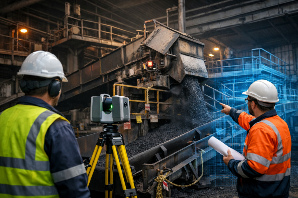
Coal plant shutdown engineering using a 3D laser scanner to capture conveyor and transfer chute infrastructure.

Engineering Applications Across Mining Infrastructure

The conversion of point clouds into engineering models is now widely used across many mining environments.

Common applications include:

  • Coal handling plants
  • Bulk materials handling infrastructure
  • Processing plants and concentrators
  • Port loading facilities
  • Conveyor systems and transfer stations
  • Industrial processing plants

By capturing existing infrastructure digitally, engineers can develop highly accurate models that support plant upgrades, shutdown planning and long-term asset management.


The Future of Digital Engineering in Mining

As scanning technology continues to improve, point cloud modelling is becoming a core component of modern mining engineering workflows.

The ability to convert real-world infrastructure into precise digital models allows engineers to design upgrades more efficiently, reduce installation risk and improve plant reliability.

For mining operators and engineering teams planning infrastructure upgrades, the integration of laser scanning, point clouds and engineering modelling is transforming how projects are designed and delivered.


Hamilton By Design logo displayed on a blue tilted rectangle with a grey gradient background

3D LiDAR scanning and 3D modelling service button โ€” laser scanner capturing a point cloud for engineering and CAD modelling
Mechanical engineering services
Name
Would you like us to arrange a phone consultation for you?
Address

CHPP Engineering title graphic featuring bold white text reading "CHPP Engineering" centred on a blue rounded rectangle background.
Pipework Drafting title graphic featuring bold white text reading "Pipework Drafting" centred on a blue rounded rectangle background.
3D LiDAR Scanning for Engineering Projects title graphic featuring bold white text on a blue rounded rectangle background.

3D CAD Modelling Australia service banner for Hamilton By Design

LiDAR vs Photogrammetry for Industrial Engineering

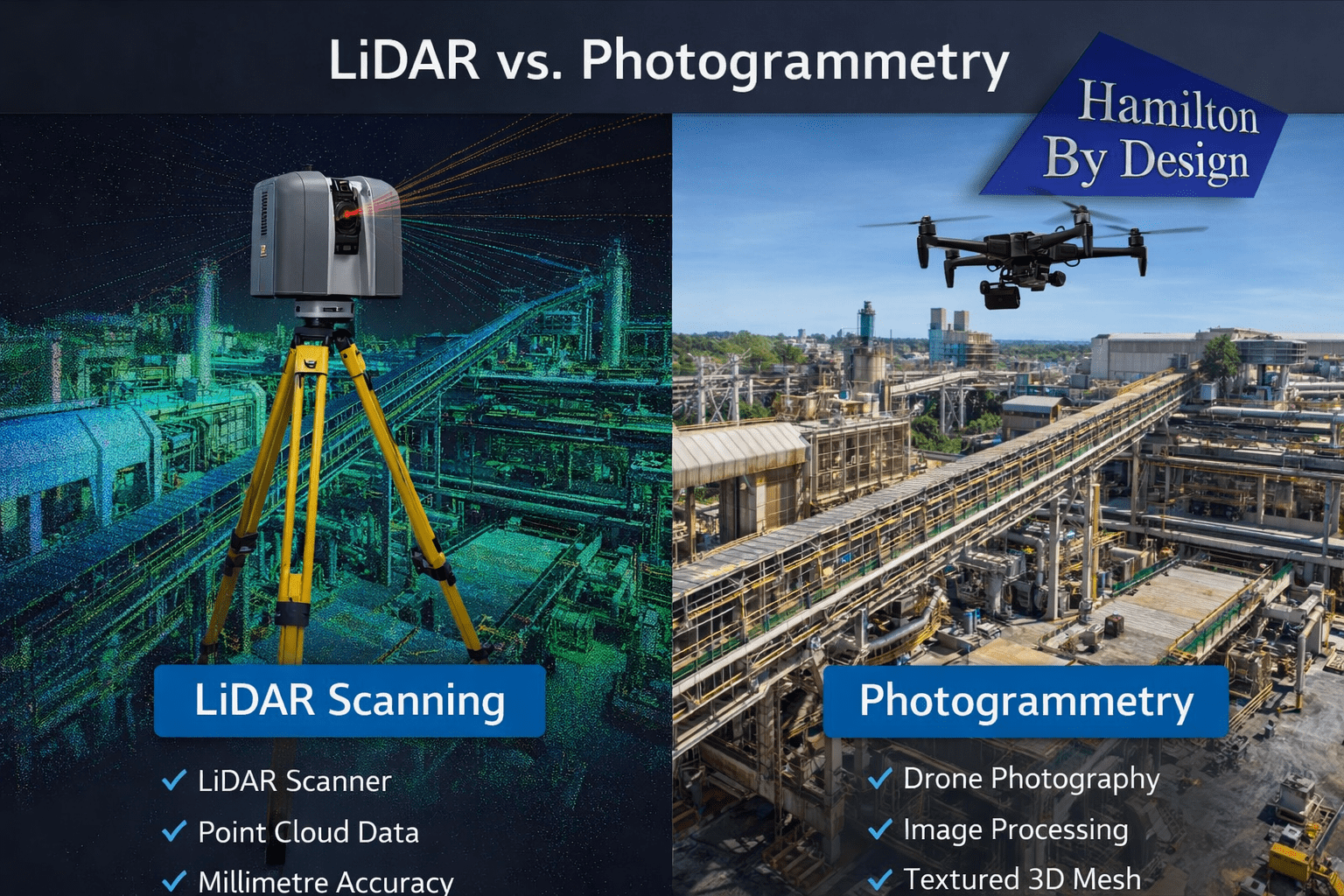
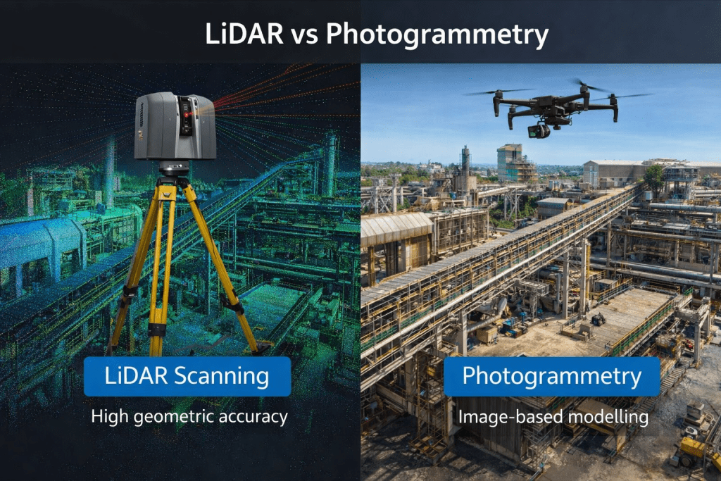
Engineering comparison of LiDAR scanning and photogrammetry used for capturing industrial plants and infrastructure.

Understanding the Difference Between LiDAR and Photogrammetry

When engineers need to capture accurate measurements of industrial infrastructure, two technologies are commonly considered: LiDAR scanning and photogrammetry.

Both methods allow engineers to create 3D digital models of real-world environments. However, when comparing LiDAR vs photogrammetry, each technology has different strengths depending on the type of engineering project.

For industries such as mining, processing plants, and heavy industrial facilities, choosing the right technology can significantly affect the accuracy, speed, and reliability of engineering design work.

At Hamilton By Design, LiDAR scanning is frequently used to capture existing conditions in complex industrial environments where precision is critical.

Learn more about engineering-grade scanning here:
https://www.hamiltonbydesign.com.au/home/engineering-grade-3d-laser-scanning-mining-industrial/


What is LiDAR Scanning?

LiDAR (Light Detection and Ranging) uses laser pulses to measure the distance between the scanner and surrounding surfaces. A terrestrial laser scanner emits millions of laser pulses per second and records the returned signal to calculate precise spatial coordinates.

The result is a dense 3D point cloud representing the scanned environment.

Engineering-grade LiDAR scanners commonly achieve millimetre-level accuracy, making them well suited for capturing industrial infrastructure such as:

  • pipework systems
  • structural steel
  • conveyors
  • tanks and vessels
  • pump stations
  • processing equipment

LiDAR scanning is widely used for plant upgrades, shutdown planning, and mechanical design where accurate site data is essential.

More information on LiDAR scanning services:
https://www.hamiltonbydesign.com.au/home/engineering-services/3d-laser-scanning/


What is Photogrammetry?

Photogrammetry is a technique that creates 3D models using photographs captured from multiple angles. Specialised software analyses overlapping images and reconstructs a three-dimensional model of the scene.

Photogrammetry is commonly used in:

  • aerial mapping
  • surveying large land areas
  • construction progress monitoring
  • environmental mapping
  • drone-based inspections

Because the technique relies on photographs rather than laser measurements, the accuracy of photogrammetry depends on factors such as image quality, lighting conditions, and camera calibration.


Comparison between LiDAR scanning and photogrammetry capturing an industrial engineering facility for 3D modelling.

LiDAR vs Photogrammetry: Key Differences

When comparing LiDAR vs photogrammetry, the main differences relate to measurement accuracy, speed of data capture, and suitability for complex environments.

FeatureLiDAR ScanningPhotogrammetry
Measurement MethodLaser distance measurementImage-based reconstruction
Typical AccuracyMillimetre-levelCentimetre-level (depending on conditions)
Performance in Low LightExcellentLimited
Surface DetailHigh geometric accuracyHigh visual detail
Performance in Complex PlantVery strongMore challenging
Data Capture SpeedVery fastModerate

For industrial engineering projects, LiDAR scanning typically provides more reliable geometric data, especially when scanning dense plant environments.


When LiDAR is Preferred in Industrial Engineering

LiDAR scanning is often the preferred technology for projects involving complex infrastructure.

Common engineering applications include:

  • plant upgrades and retrofits
  • pipework modifications
  • structural steel design
  • conveyor and materials handling systems
  • pump installations
  • shutdown planning

In these environments, millimetre-level accuracy is required to ensure new components fit correctly within existing structures.

LiDAR scanning is also effective in environments with limited lighting or reflective metal surfaces, which are common in industrial facilities.

You can read more about how engineers capture existing conditions before plant upgrades here:
https://www.hamiltonbydesign.com.au/capture-existing-conditions-before-plant-upgrades/


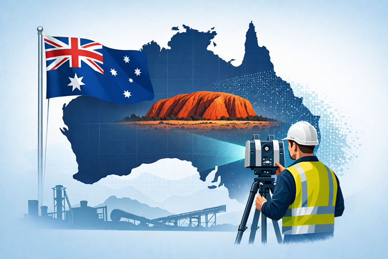
LiDAR scanning survey across Australia with engineer capturing industrial site data

When Photogrammetry is Useful

Photogrammetry remains a valuable tool for certain types of projects, particularly where large areas must be captured quickly.

Typical applications include:

  • drone-based terrain mapping
  • stockpile measurement
  • topographic surveys
  • construction progress documentation
  • infrastructure inspections

In these situations, photogrammetry provides an efficient method of capturing large datasets using aerial imagery.

However, for detailed industrial modelling, additional processing may be required to achieve the level of precision needed for engineering design.


Combining LiDAR and Photogrammetry

In some projects, engineers combine LiDAR scanning with photogrammetry to capture both accurate geometry and high-quality visual textures.

This approach can be useful when:

  • documenting heritage structures
  • visualising infrastructure for presentations
  • creating digital twins of facilities

However, for most industrial engineering applications, LiDAR scanning remains the primary technology used for accurate measurement.


From Scan Data to Engineering Models

Regardless of the capture method used, the final goal in engineering projects is often to convert the captured data into usable CAD models.

The typical workflow includes:

  1. Site data capture
  2. Data processing and alignment
  3. Point cloud generation
  4. Engineering modelling in CAD software
  5. Design and fabrication documentation

You can learn more about this process here:

Hamilton By Design logo displayed on a blue tilted rectangle with a grey gradient background

Conclusion

When comparing LiDAR vs photogrammetry, both technologies offer valuable tools for capturing real-world environments.

However, for most industrial engineering applications where accuracy and reliability are critical, LiDAR scanning typically provides the best results.

For mining, processing plants, and heavy industrial facilities, engineering-grade LiDAR scanning allows project teams to work from highly accurate digital models of existing infrastructure.

This improves design confidence, reduces installation risk, and helps ensure that new components integrate successfully with existing plant systems.

Hamilton By Design provides engineering-grade LiDAR scanning services to support industrial engineering projects across Australia.

3D LiDAR scanning and 3D modelling service button โ€” laser scanner capturing a point cloud for engineering and CAD modelling
Mechanical engineering services
Name
Would you like us to arrange a phone consultation for you?
Address
3D CAD Modelling Australia service banner for Hamilton By Design

Mechanical Engineering | Structural Engineering


3D LiDAR Scanning Darwin for engineering surveys, laser scanning, reality capture and point cloud modelling services
3D LiDAR Scanning Australia engineering services for laser scanning, reality capture, scan-to-CAD, Scan-to-BIM and as-built documentation across Australia
3D LiDAR scanning services on the Central Coast providing engineering-grade laser scanning, point cloud capture, scan-to-CAD modelling and industrial reality capture for infrastructure and industrial projects.
3D LiDAR Scanning Perth for engineering surveys, laser scanning, reality capture and point cloud modelling services
3D LiDAR Scanning Sydney for engineering surveys, laser scanning, reality capture and point cloud modelling services
3D LiDAR Scanning Brisbane for engineering surveys, laser scanning, reality capture and point cloud modelling services
3D LiDAR Scanning Canberra for engineering surveys, laser scanning, reality capture and point cloud modelling services
3D LiDAR Scanning Newcastle for engineering surveys, laser scanning, reality capture and point cloud modelling services
3D LiDAR Scanning Adelaide for engineering surveys, laser scanning, reality capture and point cloud modelling services

Scan for Conveyor Transfers

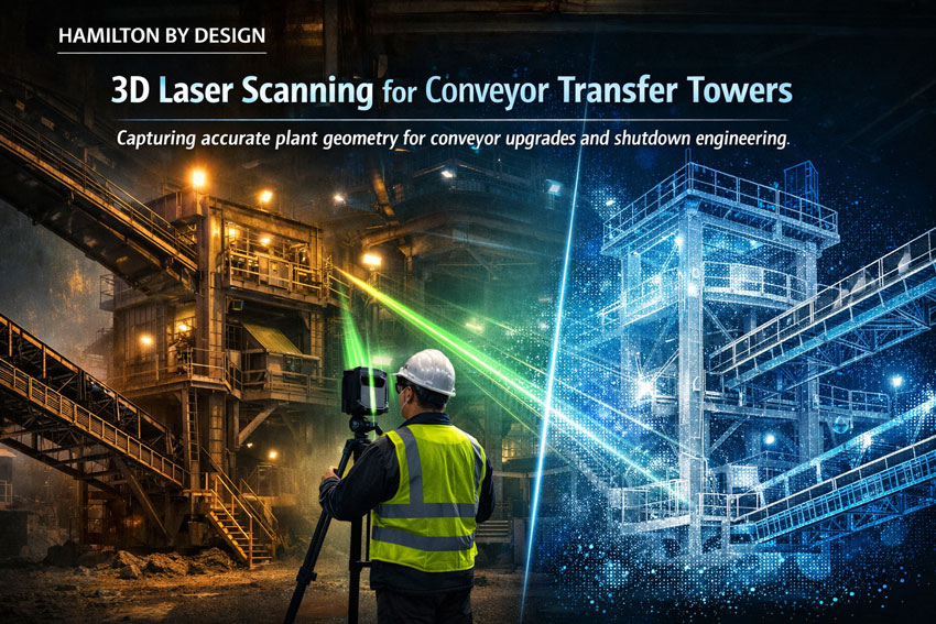
3D laser scanning of a mining conveyor transfer tower capturing point cloud data for engineering modelling.

Conveyor transfer towers are critical components within mining and bulk material handling operations. These structures control the movement of material between conveyors and often contain complex arrangements of chutes, structural steel, maintenance platforms, and access walkways.

Over time, many transfer towers are modified as production requirements change. Equipment upgrades, chute redesigns, and maintenance improvements can result in plant infrastructure that no longer matches the original engineering drawings.

For engineers planning upgrades or maintenance projects, accurate existing condition data is essential. One of the most effective ways to capture this information is through 3D laser scanning.

At Hamilton By Design, engineering-grade scanning is used to capture precise geometry of conveyor transfer towers and surrounding plant infrastructure. This data can then be converted into accurate digital models used for mechanical design, plant upgrades, and engineering analysis.

Engineer performing LiDAR scanning of a conveyor transfer tower in a mining processing plant.

Learn more about our engineering scanning capabilities here:
๐Ÿ‘‰ https://www.hamiltonbydesign.com.au/home/engineering-services/3d-laser-scanning/


Why Conveyor Transfer Towers Are Difficult to Measure

Transfer towers are often some of the most complex areas within a processing plant. They typically contain multiple systems operating within a confined structure including conveyors, transfer chutes, structural supports, and maintenance platforms.

These environments can include:

โ€ข multiple conveyors entering and exiting the structure
โ€ข chute systems with wear liners
โ€ข structural steel frames and supports
โ€ข maintenance walkways and access platforms
โ€ข dust control and service equipment

Because of the tight layout and elevation changes within these structures, traditional measurement methods can be slow and prone to error.

In many facilities, the original engineering drawings may also be outdated due to years of plant modifications.

Accurate measurement is therefore essential when designing upgrades or modifications to conveyor transfer systems.


Using 3D Laser Scanning to Capture Transfer Tower Geometry

Engineering-grade 3D laser scanning uses LiDAR technology to capture millions of spatial measurements of plant infrastructure.

The resulting dataset forms a point cloud model representing the exact geometry of conveyors, structural steel, chutes, and surrounding plant equipment.

This digital model allows engineers to analyse plant layouts and develop accurate engineering designs before physical work begins.

Laser scanning provides several advantages when working in conveyor transfer towers.

Accurate Existing Conditions

Scanning captures the true geometry of plant infrastructure, allowing engineers to design modifications based on reliable data rather than outdated drawings.

Improved Design Planning

Digital models generated from scan data allow engineers to verify clearances and identify potential clashes before installation.

Reduced Shutdown Risk

Engineering teams can plan installation work more effectively using digital models created from scan data.

Faster Data Capture

Laser scanning can capture complex structures quickly compared with traditional measurement methods.


3D Scanning for Mining Shutdown Projects

Many conveyor transfer tower upgrades are performed during planned mining shutdowns, where engineering teams must complete inspections, modifications, and installations within tight timeframes.

Laser scanning provides a fast and reliable way to capture accurate plant geometry before shutdown work begins. Engineers can then analyse the digital model and develop upgrade designs in advance.

This approach reduces the risk of unexpected installation issues during shutdown periods.

You can learn more about scanning applications during plant shutdowns here:

๐Ÿ‘‰ https://www.hamiltonbydesign.com.au/home/engineering-grade-3d-laser-scanning-mining-industrial/3d-scanning-mining-shutdown-projects/


From Laser Scan to Engineering Model

The laser scanning workflow for conveyor transfer towers typically follows a structured process.

  1. Planning scan locations within the transfer tower
  2. Capturing plant geometry using LiDAR scanners
  3. Registering scan positions to create a unified point cloud
  4. Extracting geometry from the point cloud dataset
  5. Creating engineering CAD models for design analysis

These models allow engineers to analyse plant infrastructure and design upgrade solutions with greater confidence.


Reverse Engineering Conveyor Infrastructure

In many mining plants, original equipment drawings are missing or no longer reflect the current infrastructure. In these cases, laser scanning can be used to reverse engineer existing equipment and structures.

By capturing the geometry of conveyors, chutes, and supporting structures, engineers can recreate accurate CAD models used for redesign, replacement components, or plant upgrades.

Hamilton By Design provides reverse engineering services using high-accuracy scanning technology.

Learn more about this process here:

๐Ÿ‘‰ https://www.hamiltonbydesign.com.au/reverse-engineer-3d-scanning/


Digital Engineering for Conveyor Transfer Towers

Digital models created from laser scanning allow engineers to analyse plant infrastructure in a controlled environment before work begins on site.

These models support engineering tasks such as:

โ€ข chute design and optimisation
โ€ข conveyor upgrade planning
โ€ข structural modifications
โ€ข clash detection and layout verification
โ€ข maintenance planning and documentation

For mining operations, this approach improves the reliability of plant upgrade projects and reduces engineering risk.


Engineering Support from Hamilton By Design

Hamilton By Design provides engineering-led 3D laser scanning and mechanical design services supporting mining and industrial infrastructure projects across Australia.

Our services include:

โ€ข conveyor transfer tower scanning
โ€ข plant upgrade engineering
โ€ข mechanical design and modelling
โ€ข reverse engineering of plant infrastructure
โ€ข digital engineering models and inspections

By combining scanning technology with engineering expertise, we help mining and industrial clients capture accurate plant geometry and convert it into practical engineering solutions.


Hamilton By Design logo displayed on a blue tilted rectangle with a grey gradient background

Learn More About Engineering-Grade Laser Scanning

For a full overview of engineering-grade laser scanning and its applications in mining and industrial plants, visit:
๐Ÿ‘‰ https://www.hamiltonbydesign.com.au/home/engineering-grade-3d-laser-scanning-mining-industrial/


Anthony Hamilton
Principal Engineer
Hamilton By Design


Name
Would you like us to arrange a phone consultation for you?
Address

3D CAD Modelling Australia service banner for Hamilton By Design