Project Management Challenges

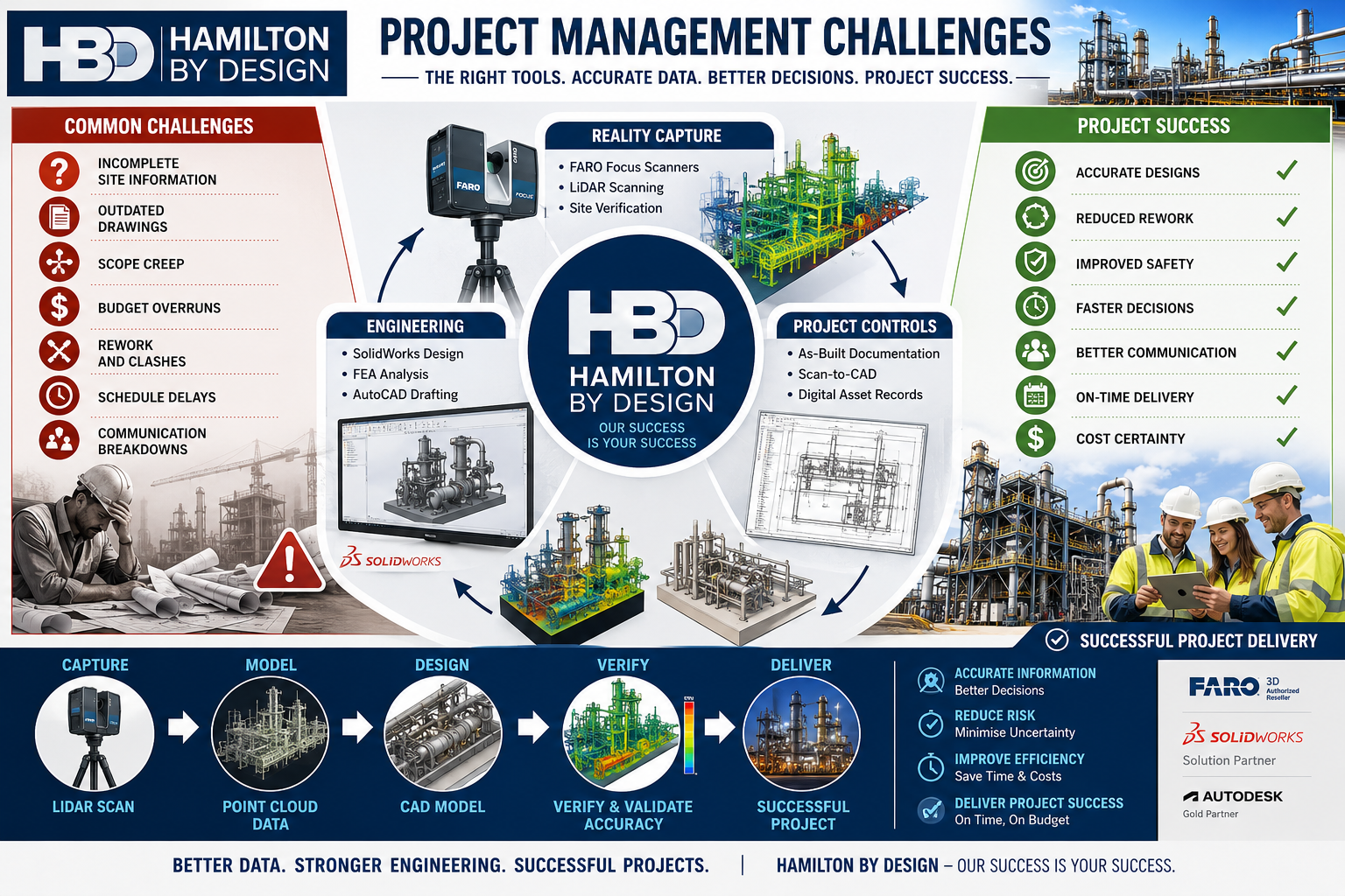
Hamilton By Design project management infographic showing how engineering-grade LiDAR scanning, reality capture, mechanical engineering, CAD modelling, and project controls help overcome common project challenges. The graphic highlights issues such as incomplete site information, outdated drawings, scope creep, budget overruns, rework, schedule delays, and communication breakdowns. It illustrates a workflow from LiDAR scanning and point cloud data through CAD modelling, verification, and successful project delivery with improved safety, reduced risk, cost certainty, and accurate engineering outcomes.

How the Right Information, 3D Scanning and Engineering Tools Drive Project Success

Your Success Is Our Success

Every project manager starts with the same objective:

Deliver a successful project safely, on time and within budget.

Whether the project involves a mining operation, manufacturing facility, port infrastructure, processing plant, water treatment facility, conveyor system, structural upgrade or equipment installation, success ultimately depends on the quality of the decisions made throughout the project lifecycle.

Unfortunately, project managers often face significant challenges:

  • Inaccurate drawings
  • Unknown site conditions
  • Scope creep
  • Communication issues
  • Budget pressures
  • Schedule constraints
  • Construction clashes
  • Fabrication errors
  • Asset documentation gaps

These challenges rarely occur because people are not trying hard enough.

Most occur because project teams are making decisions with incomplete or inaccurate information.

At Hamilton By Design, we believe project success starts with good information.

That is why we have invested in engineering-grade 3D scanning technologies, digital engineering workflows, CAD platforms, simulation tools and practical engineering expertise to help our clients reduce risk and improve project outcomes.

Your success is our success.

Learn more:


Why Projects Struggle

Project managers are expected to coordinate:

  • Asset owners
  • Operations personnel
  • Engineers
  • Contractors
  • Fabricators
  • Suppliers
  • Maintenance teams
  • Construction crews

Each stakeholder brings different priorities.

Without accurate information, even simple projects can become difficult.

Common issues include:

Drawings Do Not Match Reality

Many industrial facilities have been operating for decades.

Over time:

  • Pipework is modified
  • Equipment is replaced
  • Structures are altered
  • Temporary solutions become permanent

Unfortunately, documentation is not always updated.

Project teams may begin engineering work based on drawings that no longer represent the actual facility.

Site Conditions Are Unknown

A pipe hidden behind equipment.

An undocumented support structure.

An access issue not identified during planning.

Small surprises often become large project delays.

Rework Becomes Expensive

The cost of identifying an issue during design is significantly lower than discovering the same issue during construction.

Good information reduces rework.


The Foundation of Project Success: Accurate Information

Before discussing tools, it is important to understand a simple principle:

Every engineering decision is only as good as the information available.

Accurate information improves:

  • Planning
  • Design
  • Budgeting
  • Scheduling
  • Procurement
  • Construction

This is why modern project delivery increasingly relies on reality capture and digital engineering workflows.


Understanding 3D Scanning Technologies

Not all scanners are the same.

Different technologies suit different applications.

Selecting the correct technology is critical.


Terrestrial LiDAR Scanners

Terrestrial LiDAR scanners are commonly used for industrial facilities.

Examples include:

  • FARO Focus Series
  • Leica RTC360
  • Trimble X9

Typical applications:

  • Processing plants
  • Manufacturing facilities
  • Structural steel
  • Pipework
  • Conveyor systems
  • Buildings

Typical accuracy:

  • ยฑ1 mm to ยฑ3 mm single scan
  • ยฑ2 mm to ยฑ10 mm registered project accuracy

Benefits:

  • Accurate site verification
  • Reduced site visits
  • Improved design confidence

Hamilton By Design uses engineering-grade terrestrial LiDAR scanning to support scan-to-CAD workflows and project delivery.


Mobile LiDAR Systems

Mobile LiDAR systems allow operators to walk through facilities while collecting data.

Examples include:

  • FARO Orbis
  • NavVis VLX
  • Leica BLK2GO

Applications:

  • Warehouses
  • Large buildings
  • Facility documentation

Benefits:

  • Rapid data capture
  • Reduced field time

Limitations:

  • Lower accuracy than tripod-based systems

Structured Light Scanners

Structured light scanners project patterns onto surfaces and capture highly detailed geometry.

Applications:

  • Reverse engineering
  • Product development
  • Component modelling

Typical accuracy:

  • ยฑ0.02 mm to ยฑ0.10 mm

Portable Metrology Arms

Portable metrology systems are used for precision measurement.

Applications:

  • Machined components
  • Gearboxes
  • Pump components
  • Manufacturing inspection

Typical accuracy:

  • ยฑ0.015 mm to ยฑ0.05 mm

Drone LiDAR Systems

Drone-based systems capture large areas quickly.

Applications:

  • Mining
  • Infrastructure
  • Stockpiles
  • Terrain mapping

Typical accuracy:

  • ยฑ20 mm to ยฑ100 mm

How Hamilton By Design Uses Scanning to Improve Project Outcomes

Scanning alone does not deliver project success.

Success comes from transforming captured data into useful engineering information.

Our workflow includes:

1. Site Verification

Capture existing conditions.

2. Point Cloud Registration

Align scan data accurately.

3. Scan-to-CAD

Convert reality into engineering models.

4. Engineering Design

Develop practical solutions.

5. Design Reviews

Identify issues before fabrication.

6. Drawing Production

Generate clear construction documentation.

7. Construction Support

Assist project teams during delivery.

8. As-Built Verification

Confirm final installation.


Hamilton By Design’s Project Delivery Toolkit

FARO Focus S70

Used for:

  • Industrial facilities
  • Pipework
  • Structural steel
  • Conveyors

Benefits:

  • Accurate existing-condition information
  • Improved project confidence

SOLIDWORKS

Used for:

  • Mechanical design
  • Equipment design
  • Reverse engineering

Benefits:

  • Manufacturing-ready models
  • Parametric design

AutoCAD

Used for:

  • General arrangements
  • Fabrication drawings
  • Construction documentation

FARO SCENE

Used for:

  • Registration
  • Quality control
  • Point cloud management

Autodesk ReCap

Used for:

  • Point cloud processing
  • Scan-to-CAD workflows

Navisworks

Used for:

  • Model reviews
  • Coordination
  • Clash detection

SOLIDWORKS Simulation

Used for:

  • Stress analysis
  • Structural verification

ANSYS

Used for:

  • Advanced engineering analysis

Rocky DEM

Used for:

  • Bulk materials handling
  • Chute design
  • Conveyor systems

The Benefits to Project Managers

When accurate information is available early:

Better Planning

Teams understand site conditions.

Better Budget Control

Unexpected variations are reduced.

Better Communication

Stakeholders review the same information.

Better Constructability

Designs are reviewed before fabrication.

Better Outcomes

Projects progress with greater confidence.


Why Experience Matters

Technology alone does not solve project challenges.

Hamilton By Design combines:

  • Mechanical engineering
  • Drafting
  • Manufacturing experience
  • Site experience
  • Reverse engineering
  • Reality capture
  • Digital engineering

Our objective is not simply to collect scan data.

Our objective is to help clients deliver successful projects.


Hamilton By Design logo displayed on a blue tilted rectangle with a grey gradient background

Contact Us – Talk to Us

Name
Would you like us to arrange a phone consultation for you?
Address

Our Clients

Project success begins with reliable information.

By combining engineering-grade 3D scanning, scan-to-CAD workflows, mechanical engineering, simulation and practical project experience, Hamilton By Design helps project managers reduce uncertainty and improve outcomes.

From reality capture through to engineering design and construction support, our focus remains simple:

Your Success Is Our Success.

Learn more:

www.hamiltonbydesign.com.au

Additional engineering articles:

https://hamiltonbydesign.blogspot.com

Pipework detailing resources:

https://pipeworkdetailing.blogspot.com


Frequently Asked Questions

1. What are the biggest project management challenges?

Schedule delays, budget overruns, scope creep, poor communication and inaccurate information.

2. How does 3D scanning improve project delivery?

It provides accurate site information for planning and design.

3. What scanner does Hamilton By Design use?

The FARO Focus S70 terrestrial LiDAR scanner.

4. What is scan-to-CAD?

The process of converting scan data into engineering models and drawings.

5. How can LiDAR scanning reduce project risk?

By identifying existing conditions before design begins.

6. Can scanning reduce site visits?

Yes.

7. What industries benefit from scanning?

Mining, manufacturing, ports, infrastructure and processing plants.

8. What is a point cloud?

A digital representation of a physical environment.

9. Why is accurate information important?

Because project decisions depend on it.

10. Can scanning reduce rework?

Yes.

(Continue through FAQ 50 covering schedule management, budget control, stakeholder communication, brownfield projects, pipework modelling, structural steel, reverse engineering, shutdown planning, digital twins, clash detection, engineering analysis and project success.)


References

Hamilton By Design

www.hamiltonbydesign.com.au

Hamilton By Design Blog

https://hamiltonbydesign.blogspot.com

Pipework Detailing Blog

https://pipeworkdetailing.blogspot.com

FARO Technologies

https://www.faro.com

SOLIDWORKS

https://www.solidworks.com

ANSYS

https://www.ansys.com

Autodesk ReCap

https://www.autodesk.com/products/recap

Autodesk Navisworks

https://www.autodesk.com/products/navisworks
3D CAD Modelling Australia service banner for Hamilton By Design
Australian Drafting logo featuring bold white text reading "Australian Drafting" centred on a blue rounded rectangle background.
Engineering Governance title graphic featuring bold white text reading "Engineering Governance" centred on a blue rounded rectangle background.
Mechanical, Structural & Pipework Drafting service banner by Hamilton By Design featuring white text on a blue background.
Mechanical engineering services
Blue rounded button with the text โ€œSolidWorks Designโ€ in white.
Finite Element Analysis (FEA) engineering simulation button
3D LiDAR Scanning Darwin for engineering surveys, laser scanning, reality capture and point cloud modelling services
3D LiDAR Scanning Australia engineering services for laser scanning, reality capture, scan-to-CAD, Scan-to-BIM and as-built documentation across Australia
3D LiDAR scanning services on the Central Coast providing engineering-grade laser scanning, point cloud capture, scan-to-CAD modelling and industrial reality capture for infrastructure and industrial projects.
3D LiDAR Scanning Perth for engineering surveys, laser scanning, reality capture and point cloud modelling services
3D LiDAR Scanning Sydney for engineering surveys, laser scanning, reality capture and point cloud modelling services
3D LiDAR Scanning Brisbane for engineering surveys, laser scanning, reality capture and point cloud modelling services
3D LiDAR Scanning Canberra for engineering surveys, laser scanning, reality capture and point cloud modelling services
3D LiDAR Scanning Newcastle for engineering surveys, laser scanning, reality capture and point cloud modelling services
3D LiDAR Scanning Adelaide for engineering surveys, laser scanning, reality capture and point cloud modelling services

Brownfield Project Management

Brownfield industrial plant point cloud compared to clean Navisworks model showing real-world conditions versus design coordination

The Reality of Brownfield Development – Brownfield Project Management: Why Point Cloud Data Should Not Be Managed in Navisworks

Brownfield projects are not clean, linear, or model-driven.

They are:

  • Reactive
  • Incremental
  • Constrained by existing infrastructure
  • Driven by time, cost, and operational pressure

In this environment, the idea of maintaining a fully coordinated 3D model is often unrealistic.

A simple example illustrates this:

An electrician installs an additional power point on site. The work is completed, energised, and signed off. The drawings may be updated later โ€” the model almost never is.

This is not a failure of process โ€” it is the reality of brownfield operations.


3D LiDAR scanning and 3D modelling service button โ€” laser scanner capturing a point cloud for engineering and CAD modelling
Mechanical engineering services

Engineering Reality: From Sketch to CAD

Before anything becomes a 3D model, it starts much simpler.

As engineers, we still:

  • Sketch ideas
  • Mark up drawings
  • Discuss constraints on site

Only after this thinking process do concepts become CAD models.

This reinforces a key principle:

Engineering decisions are not driven by software โ€” software supports engineering judgement.


The Problem with Model-Centric Workflows

Platforms such as Autodesk Navisworks Manage are often positioned as central coordination tools, and in the right context they are highly effective.

However, in brownfield environments they introduce challenges:

Model Drift

  • Models quickly become outdated
  • Site changes are rarely captured in real time

High Maintenance Cost

  • Continuous updates require time and budget
  • Maintenance of models is rarely prioritised operationally

Limited Long-Term Trust

  • Teams revert back to:
    • Drawings
    • Site verification
    • Experience

The result is that the model becomes a temporary tool rather than a reliable long-term asset.


Where Multi-Discipline Coordination Actually Matters

Navisworks is most powerful when used for:

  • Multi-discipline coordination
  • Clash detection
  • Design validation

This is critical in greenfield environments where:

  • Structural, mechanical, electrical, and civil systems are designed simultaneously
  • Multiple teams work in parallel
  • Design clashes must be resolved before construction

In these cases, Navisworks plays a vital role in reducing risk and improving delivery outcomes.


Brownfield Reality: Coordination Happens on Site

In brownfield environments, the situation is very different.

Work is typically:

  • Localised
  • Task-specific
  • Carried out in isolation

Constraints are:

  • Already physically present
  • Visible and measurable
  • Managed in real time on site

In many cases:

Multi-discipline coordination is minimal or already resolved physically.

For example, an electrician installing a new outlet:

  • Reviews the environment
  • Works around existing services
  • Completes the installation

There is no model update, no coordination session, and no Navisworks workflow involved.


Point Cloud Data: The True As-Built Record

Using platforms such as FARO SCENE, point cloud data provides:

  • A direct capture of real-world conditions
  • A measurable and verifiable dataset
  • A snapshot of the plant at a point in time

Unlike models, point clouds are not interpretations โ€” they are records of reality.


3D CAD Modelling Australia service banner for Hamilton By Design

Critical Limitation: Line-of-Sight

Point cloud data is inherently line-of-sight dependent.

This means:

  • Only visible surfaces are captured
  • Occlusions create gaps in the dataset

When navigating a point cloud โ€” whether in SCENE or Navisworks โ€” moving outside original scan positions reveals these gaps.

Importantly:

  • This is not a software limitation
  • It is a fundamental characteristic of LiDAR capture

Creating a Navisworks model from a point cloud does not resolve this issue. It simply introduces another layer of processing without improving data completeness.


Why Navisworks Adds Limited Value for Point Cloud Management

If the objective is:

  • Visualisation
  • Measurement
  • Inspection

Then native scan platforms already provide these capabilities.

Within SCENE, users can:

  • Navigate freely
  • Measure accurately
  • Clip and section data
  • Access models using free viewer tools

Introducing Navisworks adds:

  • Additional processing steps
  • Data conversion (e.g. E57 to RCP)
  • Larger and duplicated datasets
  • No improvement in scan accuracy or completeness

Navisworks does not remove line-of-sight limitations, does not fill missing data, and does not enhance the underlying scan.


Best Practice: Brownfield Data Strategy

A more practical and effective approach is:

1. Point Cloud as the Primary Asset

  • Maintain original scan data (e.g. E57)
  • Store registered datasets
  • Use native platforms for access and interrogation

2. Targeted Modelling Only Where Required

  • Model critical interfaces and tie-in points
  • Avoid full plant modelling unless necessary

3. Drawings for Formal Deliverables

  • Maintain as-built documentation
  • Use redlines where appropriate

4. Navisworks for Project Phases Only

  • Apply Navisworks during major upgrades or greenfield-style coordination
  • Do not rely on it as a long-term data environment

Key Project Management Insight

Models degrade over time in brownfield environments.

Point cloud data remains a verifiable record of reality.


Conclusion

Navisworks remains a powerful tool for coordination and design validation, particularly in greenfield projects where multi-discipline interaction is high.

However, for brownfield project management:

  • Point clouds provide truth
  • Drawings provide documentation
  • Navisworks provides temporary coordination

If the objective is to visualise, measure, and understand existing conditions, managing point cloud data within native scanning platforms is more efficient, more accurate, and more sustainable than relying on Navisworks models.


One-Line Summary

In brownfield projects, the scan is the asset โ€” the model is only a moment in time.


CHPP Engineering title graphic featuring bold white text reading "CHPP Engineering" centred on a blue rounded rectangle background.
Pipework Drafting title graphic featuring bold white text reading "Pipework Drafting" centred on a blue rounded rectangle background.
3D LiDAR Scanning for Engineering Projects title graphic featuring bold white text on a blue rounded rectangle background.

Our clients

Contact Us – Talk to Us

Name
Would you like us to arrange a phone consultation for you?
Address

Project Management, Programme Control & Safety on Thai Infrastructure Projects

Engineers reviewing a project schedule beside live rail construction, illustrating the link between programme control, temporary works, and public safety in infrastructure projects.

Building the Case for Stronger Project-Management Governance on Thai Infrastructure Projects

Recent infrastructure failures in Thailand have highlighted an issue that extends beyond construction capability, technical standards, or nationality. The common thread running through these events is how large projects are governed, scheduled, and controlled.

This discussion is not about blame.
It is about delivery systems, incentives, and authority โ€” and whether current models are sufficiently robust for complex work undertaken beside live roads, rail, and the public.


The delivery context

Many major infrastructure projects in Thailand are delivered through government-to-government frameworks involving international state-linked partners, including Chinese state-owned enterprises such as China Railway Engineering Corporation and related entities.

Within these arrangements:

  • local contractors typically hold construction responsibility
  • international partners provide systems, standards, technical authority, or programme input
  • project milestones are tightly defined and politically significant

This model brings scale, funding certainty, and delivery speed. It also creates predictable pressure points that deserve closer examination.


Infrastructure project managers assessing schedules during crane operations near live rail, representing safety governance and programme control in complex urban construction.

What the recent failures tell us

The incidents that have triggered concern were not failures of rail technology or permanent structural design. They were predominantly:

  • temporary works failures
  • crane and staging incidents
  • work undertaken adjacent to live public corridors

These are execution and sequencing failures, not design failures โ€” and they are heavily influenced by programme structure and schedule control.

This leads to a fundamental governance question:

Who has the authority to change the programme when safe sequencing requires it?


Programme control is not neutral

When schedules are:

  • externally fixed
  • politically sensitive
  • commercially punitive to miss

risk does not disappear. It is transferred downward.

In practice, this often manifests as:

  • parallel work instead of sequential isolation
  • reduced exclusion zones
  • reliance on procedural controls rather than engineered separation
  • temporary works treated as โ€œmeans and methodsโ€ instead of engineered systems

None of this requires bad intent. It is a system response to inflexible programmes.


The role of Chinese state-owned enterprises

Chinese SOEs involved in these projects are not typically the principal construction contractors. However, they often exert significant influence over programme structure, milestones, and delivery expectations.

Across multiple countries, state-linked delivery models tend to exhibit consistent characteristics:

  • strong emphasis on schedule certainty
  • delegation of safety responsibility to downstream contractors
  • limited flexibility once programme commitments are set
  • incidents framed as execution issues rather than programme-design issues

Whether fair or not, this creates a perception that delivery behaviour is structurally stable and slow to change, even after serious failures.

That perception alone justifies a review of governance arrangements.


Why Australian project-management capability is relevant

Australian companies were not in project-management or programme-control roles on the projects that failed. As a result, Australian safety-governance practices were not embedded in the delivery model.

Australian project-management frameworks are shaped by:

  • acceptance that schedules must move to protect safety
  • independent temporary-works engineering and sign-off
  • explicit treatment of live-interface work as a programme risk
  • separation between commercial pressure and safety authority
  • deep experience in brownfield, shutdown, and live-asset environments

This does not make Australian firms better builders.
It makes them effective governance counterbalances in high-risk delivery environments.


The case for change

The argument is not to exclude existing partners.
It is to strengthen governance.

A more resilient delivery model could include:

  • Australian firms in programme-management or independent PM roles
  • independent temporary-works authorities reporting outside the construction chain
  • schedule-risk reviews with genuine authority to resequence work
  • clearer separation between political milestones and construction logic

These measures do not slow projects โ€” they prevent catastrophic delay caused by failure.


The central point

Safety outcomes are not determined by nationality or intent.
They are determined by who controls the programme, how flexible it is, and whether safety has real authority over time and cost.

Strengthening that authority is a rational, evidence-based step forward.


The power of the people

Real improvement in infrastructure delivery does not start with press releases.
It starts when engineers, supervisors, workers, and communities speak openly about how projects are actually delivered.

Those closest to the work experience programme pressure and safety trade-offs long before failures occur. Giving space to those voices is not about blame โ€” it is about learning, transparency, and better governance.

When people are allowed to speak, systems are forced to listen.


Hamilton By Design logo displayed on a blue tilted rectangle with a grey gradient background

Comments are open

This post is intended to encourage informed, professional discussion about project-management models, programme control, and safety governance.

The focus is on systems and incentives โ€” not nationality or individual blame.
Constructive perspectives from those with professional or on-the-ground experience are welcome.


3D LiDAR scanning and 3D modelling service button โ€” laser scanner capturing a point cloud for engineering and CAD modelling
Mechanical engineering services

Our clients:


Name
Would you like us to arrange a phone consultation for you?
Address
3D LiDAR scanning and 3D modelling service button โ€” laser scanner capturing a point cloud for engineering and CAD modelling
Mechanical engineering services
Finite Element Analysis (FEA) engineering simulation button
Mechanical engineering services

Mechanical Engineering | Structural Engineering