From Point Cloud to Engineering Documentation: Turning Existing Assets into Usable Information

Engineering-grade LiDAR scanning and digital engineering workflow showing point cloud data transformed into CAD models and fabrication-ready engineering documentation.

Industrial facilities are constantly changing. Equipment is upgraded, structures are modified, process lines evolve, and maintenance-driven changes gradually reshape plant layouts over time.

Unfortunately, engineering documentation does not always evolve at the same pace.

Many facilities eventually reach a point where the question becomes:

“What actually exists on site today?”

When drawings become outdated or documentation is missing, engineering teams can face increased project risk, fabrication challenges, and costly rework.

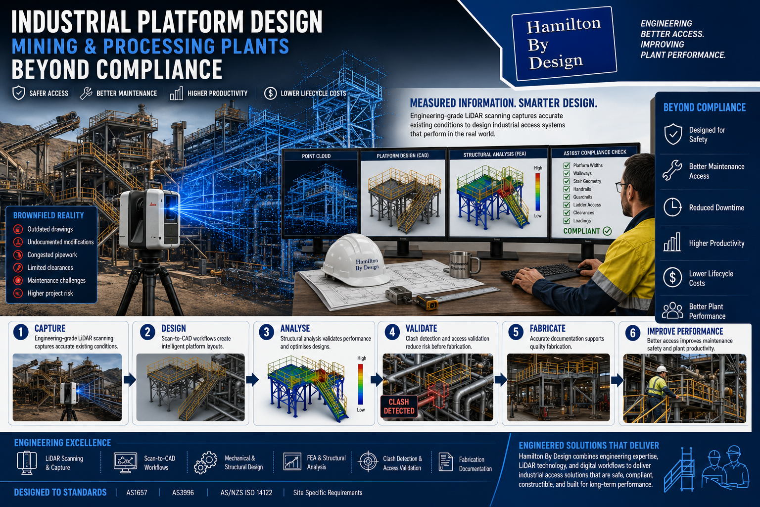
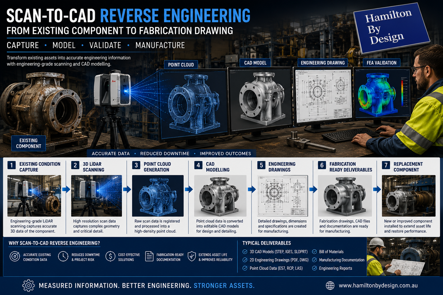
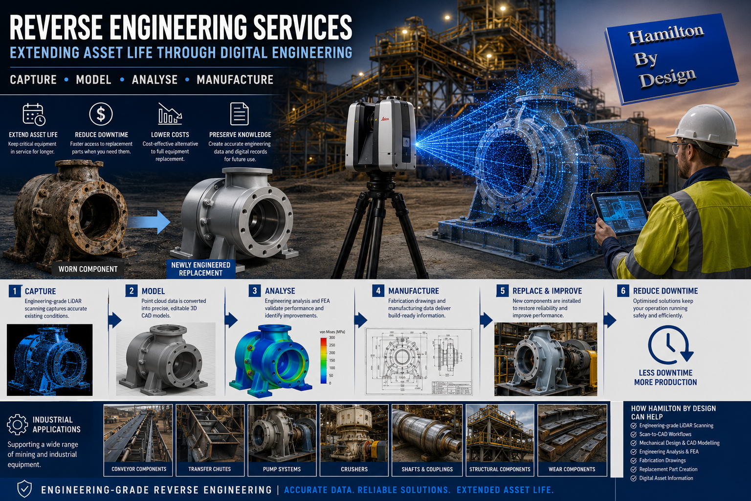
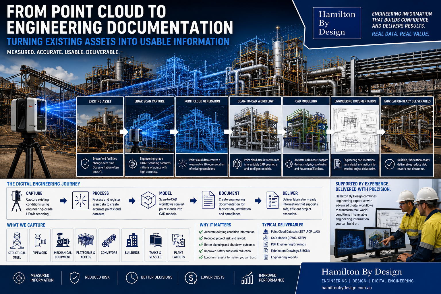
Modern digital engineering workflows now allow physical assets to be transformed into accurate engineering information through engineering-grade LiDAR scanning, point cloud generation, and Scan-to-CAD workflows.

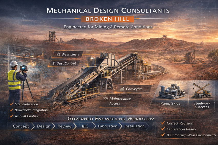
At Hamilton By Design, we support industrial and mining projects by converting real-world conditions into practical engineering deliverables that support design, fabrication, and long-term asset management.

Why Existing Information Matters

Engineering decisions rely on information.

Drawings and documentation support:

  • Plant upgrades
  • Maintenance activities
  • Shutdown planning
  • Equipment replacement
  • Fabrication projects
  • Asset management
  • Future modifications

When information becomes inaccurate, project uncertainty increases.

Potential impacts may include:

  • Installation clashes
  • Fabrication errors
  • Rework
  • Delays
  • Safety risks
  • Increased project cost

Reliable engineering information begins with understanding existing conditions.

Engineering-Grade LiDAR Scanning

The first step involves capturing the physical environment.

Hamilton By Design uses engineering-grade 3D LiDAR scanning to record:

  • Structural steel
  • Pipework
  • Mechanical equipment
  • Platforms and access systems
  • Buildings
  • Conveyors
  • Processing equipment
  • Existing plant layouts

Unlike manual measurements, LiDAR scanning captures millions of measured points from real operating environments.

Benefits can include:

  • Existing condition verification
  • Reduced assumptions
  • Improved accuracy
  • Faster information capture
  • Reduced project risk

Point Cloud Generation

Following site capture, scan information is processed into a point cloud dataset.

Point clouds provide a measurable digital representation of existing assets.

Typical outputs may include:

  • .E57 files
  • .RCP files
  • .LAS files
  • Registration reports

Point cloud datasets provide:

  • Spatial information
  • Existing geometry
  • Equipment relationships
  • Measured dimensions
  • Existing plant layouts

This information forms the foundation for engineering workflows.

Scan-to-CAD Workflows

Point cloud information becomes significantly more valuable when converted into editable engineering data.

Scan-to-CAD workflows allow engineers to transform captured geometry into:

  • Mechanical models
  • Structural models
  • Equipment layouts
  • Existing condition models
  • Plant modifications
  • Engineering assemblies

Rather than working from assumptions, engineers can work from measured information.

CAD Modelling

CAD models transform captured information into usable engineering assets.

Benefits may include:

  • Editable geometry
  • Future design flexibility
  • Improved project coordination
  • Better visualisation
  • Long-term asset information

Typical CAD outputs can include:

  • Solid models
  • Assembly models
  • Layout models
  • Mechanical drawings
  • Structural models

Digital models become valuable engineering assets beyond a single project.

Engineering Documentation

Models alone do not build equipment.

Engineering documentation converts digital information into practical project deliverables.

Documentation may include:

  • General arrangement drawings
  • Detail drawings
  • Fabrication drawings
  • Bills of materials
  • Assembly documentation
  • Engineering reports

Engineering documentation creates information that fabrication and construction teams can use confidently.

Fabrication-Ready Deliverables

The final objective is delivering usable engineering information.

Hamilton By Design deliverables may include:

  • Point cloud datasets
  • CAD models
  • PDF drawings
  • DWG files
  • STEP files
  • Fabrication documentation
  • Engineering reports

The focus is moving beyond visual models toward deliverables that support real-world implementation.

How Hamilton By Design Supports Digital Engineering

Hamilton By Design combines practical engineering knowledge and digital workflows including:

  • Engineering-grade 3D LiDAR scanning
  • Existing condition capture
  • Point cloud generation
  • Scan-to-CAD workflows
  • CAD modelling
  • Engineering documentation
  • Fabrication-ready deliverables

Our objective is creating accurate engineering information that reduces project uncertainty and supports better outcomes.

Turning Existing Assets into Usable Information

Existing assets contain valuable engineering information.

The challenge is transforming that information into something practical and usable.

3D LiDAR scanning and 3D modelling service button โ€” laser scanner capturing a point cloud for engineering and CAD modelling
Mechanical engineering services

Digital engineering workflows allow organisations to move from:

Physical Asset โ†’ Point Cloud โ†’ CAD Model โ†’ Engineering Documentation โ†’ Fabrication

When accurate information supports engineering decisions, project confidence improves.

Measured information creates better engineering outcomes than assumptions.

Hamilton By Design logo displayed on a blue tilted rectangle with a grey gradient background

Our Clients:

Name
Would you like us to arrange a phone consultation for you?
Address
Finite Element Analysis (FEA) engineering simulation button
Mechanical engineering services

Industrial Platform Design for Mining and Processing Plants: Beyond Compliance

Engineering-grade Scan-to-CAD reverse engineering workflow converting existing industrial equipment into CAD models and fabrication-ready drawings.

Industrial platforms are commonly viewed as supporting structures that simply provide access to equipment and operating areas. In many projects the design process focuses heavily on meeting minimum standards and compliance requirements.

While compliance is essential, successful platform design extends beyond satisfying engineering checklists.

Mining and processing facilities rely on platforms every day for:

  • Maintenance activities
  • Equipment inspections
  • Shutdown work
  • Operational access
  • Plant monitoring
  • Emergency access
  • Equipment removal and installation

Poor platform design can create safety concerns, maintenance challenges, and operational inefficiencies that remain throughout the life of the asset.

At Hamilton By Design, we view platform design as an engineering solution supporting productivity, maintenance, and long-term operational performance rather than simply meeting minimum requirements.

Why Industrial Platform Design Matters

Platforms directly affect how personnel interact with equipment and infrastructure.

Well-designed systems can improve:

  • Worker safety
  • Maintenance access
  • Equipment accessibility
  • Shutdown performance
  • Plant productivity
  • Long-term operating costs

Poor platform layouts may create:

  • Congested access areas
  • Restricted maintenance access
  • Increased manual handling risks
  • Difficult equipment removal
  • Longer shutdown durations
  • Increased project costs

Platform design influences how effectively a facility operates every day.

Compliance is the Starting Point

Mining and processing facilities frequently consider standards including:

  • AS1657 โ€“ Fixed Platforms, Walkways, Stairways and Ladders
  • AS3996 โ€“ Access Covers and Grates
  • Structural loading requirements
  • Site-specific engineering requirements

Standards establish minimum requirements for:

  • Platform dimensions
  • Walkway widths
  • Guardrails
  • Handrails
  • Stair geometry
  • Ladder systems
  • Access openings

Compliance is important, but meeting minimum requirements alone does not guarantee an efficient design.

3D CAD Modelling Australia service banner for Hamilton By Design

Maintenance Access Often Drives Better Outcomes

Maintenance teams commonly interact with platforms more frequently than operations personnel.

Platform design should consider:

  • Equipment removal paths
  • Tool access requirements
  • Safe working zones
  • Inspection locations
  • Clearance requirements
  • Shutdown activities
  • Future maintenance needs

Questions often worth asking include:

  • Can pumps or motors be removed safely?
  • Can maintenance teams work comfortably?
  • Is lifting equipment accessible?
  • Can personnel safely carry tools and equipment?
  • Is there room for future upgrades?

Designing around maintenance activities often improves long-term outcomes.

Human Factors Matter

Platform systems should be designed around how people actually move and work.

Human considerations can include:

  • Visibility
  • Reach distances
  • Working posture
  • Congestion
  • Manual handling requirements
  • Access frequency
  • Emergency escape routes

Designs that ignore human interaction can create unnecessary operational difficulties.

Brownfield Environments Create Additional Challenges

Most mining and processing facilities are not greenfield sites.

Brownfield facilities commonly include:

  • Existing structural steel
  • Pipework congestion
  • Historical modifications
  • Equipment additions
  • Limited clearances
  • Legacy infrastructure

Existing drawings may no longer represent current operating conditions.

Designing new platforms around assumptions can increase:

  • Fabrication risk
  • Site rework
  • Installation delays
  • Shutdown costs

Engineering-Grade LiDAR Scanning for Existing Condition Capture

Hamilton By Design supports platform projects through engineering-grade 3D LiDAR scanning.

Scanning may capture:

  • Structural steel
  • Existing platforms
  • Pipework
  • Equipment
  • Access systems
  • Buildings
  • Existing clearances

Measured information supports engineering decisions using actual site conditions rather than assumptions.

From Point Clouds to Platform Design

Captured information can be processed into engineering workflows through Scan-to-CAD systems.

This supports:

  • Existing condition modelling
  • Platform layouts
  • Structural design
  • Clash detection
  • Access validation
  • Fabrication drawings

Potential problems can often be identified digitally before fabrication begins.

Engineering Analysis and Validation

Platform systems frequently require engineering validation beyond simple geometry.

Hamilton By Design may support projects through:

  • Structural assessment
  • Finite Element Analysis (FEA)
  • Load validation
  • Design optimisation
  • Fabrication documentation

The objective is delivering practical designs that perform in operating environments.

How Hamilton By Design Supports Industrial Platform Projects

Hamilton By Design combines practical engineering experience and digital engineering workflows including:

  • Engineering-grade 3D LiDAR scanning
  • Existing condition capture
  • Scan-to-CAD workflows
  • Mechanical and structural design
  • Engineering analysis and simulation
  • CAD modelling
  • Fabrication documentation
3D LiDAR scanning and 3D modelling service button โ€” laser scanner capturing a point cloud for engineering and CAD modelling
Mechanical engineering services

Beyond Compliance

Industrial platform design should support more than standards compliance.

Successful designs support:

  • Safer workplaces
  • Better maintenance access
  • Reduced downtime
  • Improved operational efficiency
  • Lower lifecycle costs
  • Long-term asset performance

Standards establish minimum requirements.

Engineering adds value beyond them.

Better platform design supports better plant performance.

Hamilton By Design logo displayed on a blue tilted rectangle with a grey gradient background

Our Clients:

Name
Would you like us to arrange a phone consultation for you?
Address

From Existing Component to Fabrication Drawing: How Scan-to-CAD Supports Reverse Engineering

Engineering-grade Scan-to-CAD reverse engineering workflow converting existing industrial equipment into CAD models and fabrication-ready drawings.

Industrial facilities commonly rely on equipment that has operated for many years through upgrades, repairs, and ongoing modifications. Over time, engineering drawings may be lost, equipment may be altered from original configurations, or replacement components may become difficult to source.

When maintenance teams need to reproduce a component or modify an existing system, the challenge often becomes clear:

“We have the physical component, but we do not have the engineering information.”

Reverse engineering supported by Scan-to-CAD workflows provides a practical solution by converting physical assets into accurate digital engineering information.

At Hamilton By Design, we combine engineering-grade 3D LiDAR scanning, CAD modelling, and engineering documentation to transform existing components into fabrication-ready deliverables that support maintenance, upgrades, and improved asset management.

What is Scan-to-CAD Reverse Engineering?

Scan-to-CAD reverse engineering involves capturing a physical object or existing asset and converting it into editable engineering models and documentation.

Rather than relying on manual measurements or assumptions, engineering teams can create digital representations based on accurate measured information.

The workflow typically moves through:

Physical Component โ†’ Digital Capture โ†’ CAD Model โ†’ Engineering Documentation โ†’ Fabrication

The objective is creating engineering information that can support manufacturing and future asset management.

Existing Condition Capture

Reverse engineering begins with understanding the actual condition of an existing component.

Equipment operating in mining and industrial environments commonly experiences:

  • Wear
  • Modifications
  • Distortion
  • Repairs
  • Build-up
  • Material loss
  • Damage

Capturing existing conditions accurately becomes critical.

Typical assets may include:

  • Pump components
  • Shafts
  • Conveyor systems
  • Transfer chutes
  • Structural components
  • Wear liners
  • Mechanical assemblies
  • Processing equipment

Accurate existing condition capture reduces uncertainty before engineering work begins.

3D CAD Modelling Australia service banner for Hamilton By Design

Engineering-Grade 3D LiDAR Scanning

Hamilton By Design uses engineering-grade 3D LiDAR scanning to capture component geometry and surrounding environments.

LiDAR scanning can capture:

  • Complex geometry
  • Existing plant layouts
  • Mechanical equipment
  • Structural components
  • Dimensional relationships
  • Access constraints

Benefits may include:

  • Reduced manual measurement requirements
  • Improved accuracy
  • Faster information capture
  • Existing condition verification
  • Reduced engineering assumptions

Point Cloud Generation

Following site capture, scan information is processed into a point cloud dataset.

Point clouds provide:

  • Measured spatial information
  • Existing geometry
  • Dimensional verification
  • Digital representation of physical assets

Point cloud information becomes the foundation for further engineering development.

Point cloud deliverables may include:

  • .E57 files
  • .RCP files
  • .LAS files
  • Registration reports

Rather than relying on estimated dimensions, engineering decisions can be based on measured information.

CAD Modelling

Once point cloud information is generated, components can be converted into editable engineering models.

CAD modelling allows engineers to create:

  • Parametric models
  • Mechanical assemblies
  • Manufacturing geometry
  • Equipment layouts
  • Design modifications
  • Engineering improvements

Benefits include:

  • Improved visualisation
  • Future design flexibility
  • Digital asset information
  • Improved project coordination

For reverse engineering projects, editable CAD models become valuable long-term assets.

Engineering Drawings

Digital models can then be transformed into engineering documentation supporting fabrication and manufacturing activities.

Typical outputs include:

  • General arrangement drawings
  • Detail drawings
  • Assembly drawings
  • Dimensional drawings
  • Manufacturing drawings
  • Bills of materials

Documentation provides manufacturing teams with clear information for production.

Fabrication-Ready Deliverables

The final stage involves developing information that supports practical project execution.

Hamilton By Design deliverables may include:

  • 3D CAD models
  • PDF engineering drawings
  • DWG files
  • STEP files
  • Point cloud datasets
  • Manufacturing documentation
  • Engineering reports

The goal is delivering information that moves beyond visualisation and becomes usable engineering data.

Why Scan-to-CAD Matters for Reverse Engineering

Without digital engineering workflows, organisations may face:

  • Manual measurement errors
  • Missing information
  • Extended downtime
  • Increased fabrication risk
  • Higher project costs
  • Rework during installation

Scan-to-CAD workflows can improve:

  • Accuracy
  • Planning
  • Asset management
  • Fabrication outcomes
  • Project confidence
  • Long-term equipment support
3D LiDAR scanning and 3D modelling service button โ€” laser scanner capturing a point cloud for engineering and CAD modelling
Mechanical engineering services

How Hamilton By Design Supports Reverse Engineering Projects

Hamilton By Design combines practical engineering experience with digital engineering tools including:

  • Engineering-grade 3D LiDAR scanning
  • Existing condition capture
  • Scan-to-CAD workflows
  • CAD modelling
  • Engineering drawings
  • Fabrication documentation
  • Reverse engineering services

The objective is not simply reproducing components.

The objective is transforming existing assets into accurate engineering information that supports maintenance, manufacturing, and long-term operational performance.

Measured information creates better engineering outcomes than assumptions.

Our Clients:

Hamilton By Design logo displayed on a blue tilted rectangle with a grey gradient background
Name
Would you like us to arrange a phone consultation for you?
Address

Reverse Engineering for Mining and Industrial Equipment: Extending Asset Life

Engineering-grade reverse engineering workflow showing LiDAR scanning, CAD modelling, and FEA analysis used to recreate industrial equipment components.

Mining and industrial facilities often operate equipment for many years beyond its original installation date. Over time, machinery evolves through repairs, modifications, upgrades, and changing operational requirements. While equipment may continue performing effectively, obtaining replacement components can become increasingly difficult.

One of the most common challenges faced by industrial operations is finding replacement parts for ageing equipment where:

  • Original equipment manufacturers (OEMs) no longer support the product
  • Engineering drawings are unavailable
  • Documentation has been lost
  • Components have become obsolete
  • Lead times are excessive
  • Full equipment replacement becomes expensive

In these situations, reverse engineering can provide a practical pathway to maintain equipment performance and extend asset life.

At Hamilton By Design, we support mining and industrial operations through engineering-grade reverse engineering workflows incorporating 3D LiDAR scanning, CAD modelling, engineering analysis, and fabrication-ready documentation.

What is Reverse Engineering?

Reverse engineering involves capturing and analysing an existing component or system to recreate accurate engineering information.

Rather than starting from a new concept design, the process begins with an existing asset and develops:

  • Digital geometry
  • Engineering drawings
  • CAD models
  • Dimensional information
  • Design documentation
  • Manufacturing information

The goal is creating accurate engineering data that supports maintenance, fabrication, and equipment improvement.

Why Mining and Industrial Operations Use Reverse Engineering

Many industrial facilities contain equipment that may have operated for decades.

Examples include:

  • Conveyors
  • Transfer chutes
  • Pumps
  • Crushers
  • Structural components
  • Wear liners
  • Shafts
  • Fabricated assemblies
  • Mechanical components
  • Materials handling systems

As equipment ages, facilities can encounter increasing challenges obtaining replacement parts.

3D CAD Modelling Australia service banner for Hamilton By Design

Common issues include:

  • Obsolete components
  • Long manufacturing lead times
  • Missing drawings
  • Unknown modifications
  • Reduced OEM support
  • Increased maintenance costs

Reverse engineering helps bridge this information gap.

Obsolete Components and Missing Documentation

A common situation occurs when maintenance teams identify a failed component but no manufacturing information exists.

Examples may include:

  • Worn shafts
  • Custom brackets
  • Conveyor components
  • Pump assemblies
  • Structural items
  • Wear components

Without engineering information, organisations may face:

  • Extended downtime
  • Emergency fabrication
  • Manual measurement errors
  • Increased costs

Reverse engineering can convert physical components into accurate engineering data.

Extending Equipment Life

Full equipment replacement is not always necessary.

In many situations:

  • The surrounding system remains functional
  • Only selected components require replacement
  • Minor improvements may improve performance
  • Existing equipment can continue operating effectively

Extending equipment life may provide:

  • Lower capital expenditure
  • Reduced project risk
  • Reduced downtime
  • Improved return on investment
  • Improved operational continuity

Replacement Part Creation

Hamilton By Design can support replacement component development through engineering workflows including:

Existing Condition Capture

Capture existing equipment using:

  • Engineering-grade LiDAR scanning
  • Physical measurements
  • Dimensional verification

CAD Modelling

Develop:

  • Editable CAD models
  • Mechanical assemblies
  • Manufacturing information

Engineering Drawings

Generate:

  • General arrangement drawings
  • Fabrication drawings
  • Manufacturing documentation

Engineering Validation

Support projects through:

  • Design assessment
  • Engineering analysis
  • Finite Element Analysis (FEA)
  • Structural validation

Reducing Downtime

Unexpected equipment failures can significantly affect production.

Potential impacts may include:

  • Lost production
  • Shutdown delays
  • Increased labour requirements
  • Emergency maintenance costs
  • Reduced operational efficiency

Reverse engineering can support maintenance planning by creating:

  • Digital spare part libraries
  • Engineering records
  • Manufacturing information
  • Improved replacement processes

This allows organisations to move from reactive responses toward more structured asset management.

Cost Versus Full Equipment Replacement

Replacing an entire system can involve:

  • High capital cost
  • Long procurement timeframes
  • Installation costs
  • Production interruptions
  • Project risk

Reverse engineering may provide an alternative where:

  • Existing equipment remains suitable
  • Only selected components require replacement
  • Performance improvements can be introduced

Engineering decisions can then focus on lifecycle value rather than simply replacing complete systems.

Industrial Applications

Reverse engineering can support:

Mining Operations

  • Conveyor systems
  • Transfer chutes
  • Crushers
  • Pump systems
  • Structural assets
  • Processing equipment

Manufacturing Facilities

  • Production equipment
  • Mechanical assemblies
  • Custom components

Industrial Processing Plants

  • Wear components
  • Mechanical equipment
  • Plant modifications
  • Existing assets
3D LiDAR scanning and 3D modelling service button โ€” laser scanner capturing a point cloud for engineering and CAD modelling
Mechanical engineering services

How Hamilton By Design Supports Reverse Engineering Projects

Hamilton By Design combines engineering tools and practical engineering experience to support reverse engineering projects through:

  • Engineering-grade 3D LiDAR scanning
  • Scan-to-CAD workflows
  • Mechanical design
  • CAD modelling
  • Engineering analysis and FEA
  • Fabrication documentation
  • Existing condition verification

The objective is not simply reproducing a component.

The objective is creating reliable engineering information that supports productivity, maintenance, and long-term asset performance.

Engineering-grade reverse engineering helps transform ageing assets from a limitation into an opportunity for improved operational performance.

Our Clients:

Mechanical Design Consultants Broken Hill โ€“ Engineering for Mining, Materials Handling and Industrial Durability

Mechanical Design Consultants Broken Hill banner featuring mining conveyor system, chute transfers and governed engineering workflow.

Mechanical Design Consultants Broken Hill | Mining & Industrial Engineering

Broken Hill is more than an iconic Australian mining town โ€” itโ€™s a living industrial environment where mechanical design means engineering solutions that withstand harsh climate, challenging site conditions and highly specialised plant requirements.

At Hamilton By Design, we provide Mechanical Design Consultants Broken Hill services that go beyond drafting. We deliver practical engineering, fabrication-ready documentation and on-site validation for projects tied to mining, materials handling, industrial process systems and structural upgrades throughout the region.


Broken Hill mining mechanical engineering visual with site verification, conveyors, pump skids and steelwork design.

Why Mechanical Design in Broken Hill Is Unique

Broken Hillโ€™s heritage and industrial character make it unlike typical metropolitan engineering contexts. Key factors influencing mechanical design here include:

Mining Legacy and Heavy Industry
Broken Hillโ€™s economy is centred on mining โ€” zinc, lead, silver and associated concentrates. Mechanical design solutions must integrate with existing plant infrastructure, high wear environments and heavy materials handling.

Harsh Climate Conditions
Extreme summer heat, dusty conditions and significant thermal expansion cycles impact equipment life and material performance. Engineering design must account for thermal stresses, corrosion resistance and maintainability over extended asset life.

Remote Logistics and Cost Sensitivity
Because Broken Hill is distant from major fabrication centres, rework and revision errors are expensive in both time and cost. Mechanical design must be right the first time with robust documentation and controlled revision systems.


Mechanical Design Services Tailored to Broken Hill Industry

Hamilton By Design provides a range of mechanical design consulting services that support Broken Hillโ€™s key industrial and mining projects.


Chute Design & Transfer Systems

Material flow equipment such as chutes and transfer points are critical in mining operations. We design and optimise:

  • Rock and ore chutes
  • Dust-controlโ€‰feed transfers
  • Wear-liner selection and replaceable panels
  • Structural support interfaces

Our designs minimise plugging, reduce abrasion wear and improve operational reliability within dusty and high-impact environments.


Conveyor Systems

Conveyors move heavy materials across site, often over extended distances and challenging terrain. Design considerations we incorporate include:

  • Conveyor frame layout and structural routing
  • Loading and take-up systems
  • Belt alignment and tensioning
  • Access platforms and maintenance walkways
  • Integration with processing plant interfaces

Our designs are 3D modelled, clash-checked and documented for first-time fabrication and installation.


Pump Skids and Process Mechanical

Hydraulic systems and processing modules require precise mechanical design, especially in mobile or modular mining applications:

  • Pump skid engineering
  • Piping layout and support design
  • Equipment anchoring and vibration isolation
  • Corrosion protection in abrasive or corrosive environments

We produce fabrication-ready documentation and coordinated layouts that fit site constraints and satisfy engineering governance.


Steelwork, Cranes and Structural Interfaces

Heavy steelwork and lifting systems are common in Broken Hill facilities. Our services include:

  • Structural support and lifting frame design
  • Workshop steel detailing
  • Light crane and jib crane integration
  • Lift points, access platforms and walkways
  • Compliance with Australian steelwork and crane standards

Whether upgrading existing infrastructure or designing new installations, our mechanical design integrates structure and mechanical integrity.


Brownfield Engineering and On-Site Validation

Many Broken Hill projects occur in live facilities with legacy equipment and tight access constraints. Hamilton By Design uses verification methods such as laser scanning and measured site capture to reduce design assumptions and ensure fit-for-site outcomes.

By combining 3D modelling with real-world site conditions, we eliminate costly guesswork and minimise installation revisions.


Governance and Documentation that Reduces Risk

High freight costs, remote fabrication and limited on-site rework options mean that mechanical design documentation must be perfectly controlled. We deliver:

  • Revision-controlled issue states (Concept โ†’ Design โ†’ Review โ†’ IFC)
  • Clear markups and revision histories
  • Digital engineering workflows
  • Maintainability-centred design

This structured approach improves contractor alignment, reduces RFIs and lowers risk across the project lifecycle.


Supporting Mining and Industrial Clients in Broken Hill

From conveyor upgrades to chute optimisation, pump skid engineering to structural crane work, Hamilton By Design applies disciplined mechanical design that solves real Broken Hill problems.

We work with:

  • Mining operations and concentrator plants
  • Materials handling facilities
  • Industrial process upgrades
  • Remote site mechanical installations

Our designs are engineered for durability, constructability and long-term performance.


Hamilton By Design logo displayed on a blue tilted rectangle with a grey gradient background
3D LiDAR scanning and 3D modelling service button โ€” laser scanner capturing a point cloud for engineering and CAD modelling
Mechanical engineering services

Mechanical Design Consultants Broken Hill โ€“ Letโ€™s Talk

If your project in Broken Hill or regional NSW requires experienced mechanical design consulting โ€” whether itโ€™s conveyors, chutes, steelwork, process modules or structural interfaces โ€” Hamilton By Design is ready to support you with practical engineering that works on site.

Contact us today to discuss your mechanical design needs and get solutions that are precise, controlled and ready to build.

Name
Would you like us to arrange a phone consultation for you?
Address

3D CAD Modelling Australia service banner for Hamilton By Design

Identifying Fastener Threads in the Field

Metric vs American vs British Threads โ€” and the Australian Standards That Govern Them

In maintenance workshops and brownfield sites, one of the most common hidden problems is not bolt strength โ€” it is thread identification.

Equipment imported from the USA, Europe and the UK often ends up assembled together on Australian sites.
The bolts may look identical.
They may even screw together.

But they are not interchangeable.

Incorrect thread matching damages load capacity, prevents correct preload, and leads to loosening, fatigue cracking and eventual failure.

This guide explains the major fastening thread systems encountered in Australia (excluding pipe threads), how to recognise them, and the Australian Standards that apply.


1. The Three Fastener Thread Systems

There are three main fastening thread families encountered in mechanical and structural equipment:

SystemOriginThread AngleTypical Location
Metric ISOAustralia / Europe / modern equipment60ยฐMost modern machinery
Unified (UNC/UNF)USA60ยฐMining & imported plant
Whitworth (BSW/BSF/BA)UK / older Commonwealth55ยฐOlder equipment & legacy machinery

Even though UNC and Metric share a 60ยฐ angle, the pitch is different โ€” therefore they are not compatible.

Whitworth threads are particularly problematic because they will partially screw into metric or UNC holes before binding.


2. Metric Threads (ISO Metric โ€” Australian Standard Fasteners)

These are the primary fastening threads used in Australia.

(Coarse pitch series)

SizeMajor DiameterPitchMinor Diameter (approx)
M66.0 mm1.04.8 mm
M88.0 mm1.256.5 mm
M1010.0 mm1.58.2 mm
M1212.0 mm1.759.9 mm
M1616.0 mm2.013.8 mm
M2020.0 mm2.517.3 mm
M2424.0 mm3.020.8 mm

Fine pitch versions also exist for vibration and adjustment applications.

Typical Uses

  • Structural steel connections
  • Machinery assembly
  • Guards and access platforms
  • General engineering

3. Unified American Threads (UNC / UNF)

Common on imported mining and mobile equipment.

UNC โ€“ Coarse

SizeMajor DiameterPitch
1/4-206.35 mm1.27 mm
3/8-169.53 mm1.59 mm
1/2-1312.70 mm1.95 mm
3/4-1019.05 mm2.54 mm
1-825.40 mm3.18 mm

UNF โ€“ Fine

Used where vibration resistance is required.

Key Characteristic
UNC bolts will often start threading into metric holes but will not achieve correct preload.


4. British Threads (Whitworth Form)

Recognised by their 55ยฐ thread angle.

BSW โ€“ Coarse

SizeMajor DiameterPitch
1/4 BSW6.35 mm1.34 mm
3/8 BSW9.53 mm1.59 mm
1/2 BSW12.70 mm2.12 mm
3/4 BSW19.05 mm2.54 mm

BSF โ€“ Fine

Used historically in machinery.

BA Threads

Small instrumentation and electrical fasteners.

Typical Location

  • Pre-1980 plant
  • UK imported machinery
  • Electrical equipment

Why Incorrect Thread Matching Causes Failures

Threads do not primarily carry shear load โ€” they generate preload.

If pitch or angle differs:

  • preload is reduced
  • flank contact is uneven
  • joint loosens under vibration
  • fatigue cracking begins

Many failures blamed on vibration are actually incorrect thread engagement.


Field Identification Tips

ObservationLikely Thread
Marked M12Metric
Fraction size (1/2, 3/4)UNC/UNF or Whitworth
Smooth but tight engagementWrong pitch
Binds after 2 turnsWhitworth vs Metric

Thread gauge confirmation is always recommended.


Australian Standards Relating to Fastener Threads

Metric Thread Geometry

AS 1721 โ€” General purpose metric screw threads
AS 1275 โ€” Metric screw threads for fasteners

Fastener Product Standards

AS 1110 โ€” Metric hex bolts and screws
AS 1111 โ€” Commercial hex bolts and screws
AS 1112 โ€” Hexagon nuts
AS 1420 โ€” Socket head cap screws

Mechanical Properties

AS/NZS 4291.1 โ€” Mechanical properties of bolts, screws and studs
AS/NZS 4291.2 โ€” Mechanical properties of nuts
ISO 898-1 / ISO 898-2 โ€” Adopted strength properties
ISO 3506 โ€” Stainless steel fasteners

Structural Bolting

AS/NZS 1252 โ€” High strength structural bolting assemblies
AS 4100 โ€” Steel structures design
AS/NZS 5131 โ€” Fabrication and erection of structural steel

Coatings and Fit Allowances

AS/NZS 1214 โ€” Galvanised coatings on threaded fasteners
AS/NZS 4680 โ€” Hot dip galvanising
AS 2312.2 โ€” Corrosion protection guide
AS 1897 โ€” Electroplated coatings

3D LiDAR scanning and 3D modelling service button โ€” laser scanner capturing a point cloud for engineering and CAD modelling
Mechanical engineering services
Name
Would you like us to arrange a phone consultation for you?
Address

3D CAD Modelling Australia service banner for Hamilton By Design