Why Engineering-Grade Scanning Matters in Reverse Engineering Projects

Engineering-grade LiDAR scanning workflow comparing basic scanning and reverse engineering processes for industrial equipment.

Reverse engineering projects often begin with a simple challenge:

“We have the component, but we do not have the engineering information.”

Mining and industrial operations frequently rely on equipment that has been modified, repaired, or operating for many years beyond original installation. Drawings may no longer exist, replacement parts may be difficult to source, and physical components may have changed from their original design.

In these situations, reverse engineering allows existing equipment to be captured and converted into usable engineering information.

However, not all scanning methods deliver the same outcome.

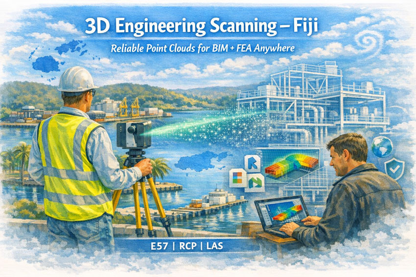
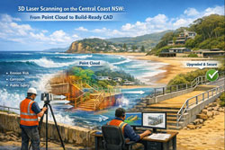
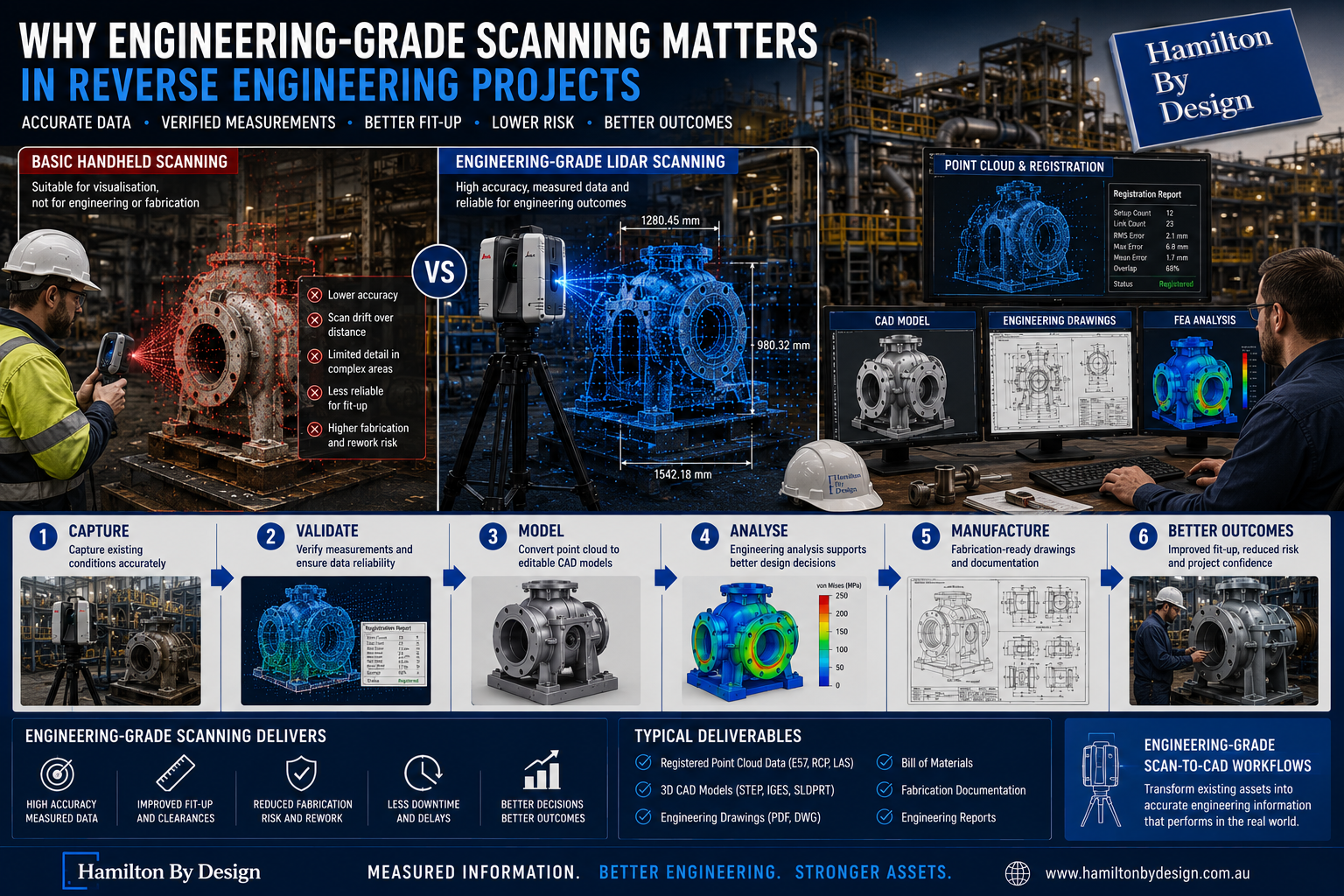
At Hamilton By Design, we use engineering-grade scanning workflows to support reverse engineering projects where accuracy, fit-up, and fabrication outcomes matter.

The objective is not simply creating a visual model.

The objective is creating reliable engineering information.

Why Scanning Accuracy Matters

Reverse engineering projects frequently involve components where small dimensional variations can create significant downstream impacts.

Examples may include:

  • Pump assemblies
  • Conveyor systems
  • Transfer chutes
  • Shafts and couplings
  • Structural components
  • Wear liners
  • Mechanical assemblies

Minor dimensional errors can potentially create:

  • Misalignment
  • Installation difficulties
  • Increased wear
  • Rework
  • Downtime
  • Manufacturing delays

A model that looks correct visually may not necessarily be suitable for fabrication or engineering analysis.

For engineering projects, measured information is critical.

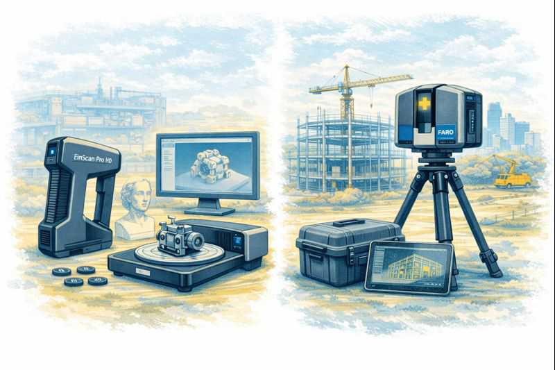
Handheld Scanning vs Terrestrial Scanning

Different scanning technologies are suited to different applications.

3D CAD Modelling Australia service banner for Hamilton By Design

Handheld Scanning Systems

Handheld systems may provide advantages including:

  • Rapid scanning
  • Mobility
  • Convenience
  • Fast visualisation

These systems are commonly used for:

  • Demonstrations
  • General visual models
  • Consumer products
  • Smaller objects
  • Architectural walkthroughs

However, challenges may include:

  • Drift over larger areas
  • Reduced positional control
  • Limited accuracy over extended environments
  • Difficulty in complex industrial sites

Engineering-Grade Terrestrial Scanning

Engineering-grade terrestrial LiDAR systems are typically designed for:

  • Existing condition capture
  • Industrial facilities
  • Brownfield environments
  • Structural information
  • Mechanical equipment
  • Engineering workflows

Potential benefits include:

  • High positional accuracy
  • Measured spatial relationships
  • Existing condition verification
  • Repeatable information capture
  • Better support for engineering decisions

The goal is producing information suitable for engineering use rather than visualisation alone.

Measurement Validation

Engineering workflows often require verification rather than assumptions.

Validation processes may include:

  • Dimensional checks
  • Registration reports
  • Measurement verification
  • Control point assessment
  • Existing condition review

Measurement validation helps ensure information can support:

  • Design development
  • Engineering analysis
  • Manufacturing
  • Construction activities

Confidence in the information improves confidence in the outcome.

Mechanical Fit-Up Requirements

Reverse engineering projects frequently involve equipment that must physically integrate with existing systems.

Examples may include:

  • Conveyor modifications
  • Pump replacements
  • Structural upgrades
  • Access platforms
  • Mechanical assemblies
  • Wear components

Poor fit-up can create:

  • Site rework
  • Delays
  • Fabrication changes
  • Additional labour
  • Installation difficulties

Engineering-grade capture helps reduce uncertainty before fabrication begins.

Brownfield Environments Create Additional Challenges

Brownfield facilities rarely match original documentation.

Industrial sites commonly include:

  • Historical modifications
  • Congested layouts
  • Existing pipework
  • Structural changes
  • Equipment additions
  • Limited access areas

These environments create challenges for reverse engineering because:

  • Drawings may be outdated
  • Components may differ from original designs
  • Existing clearances may be limited

Engineering-grade scanning provides measurable information from the actual operating environment.

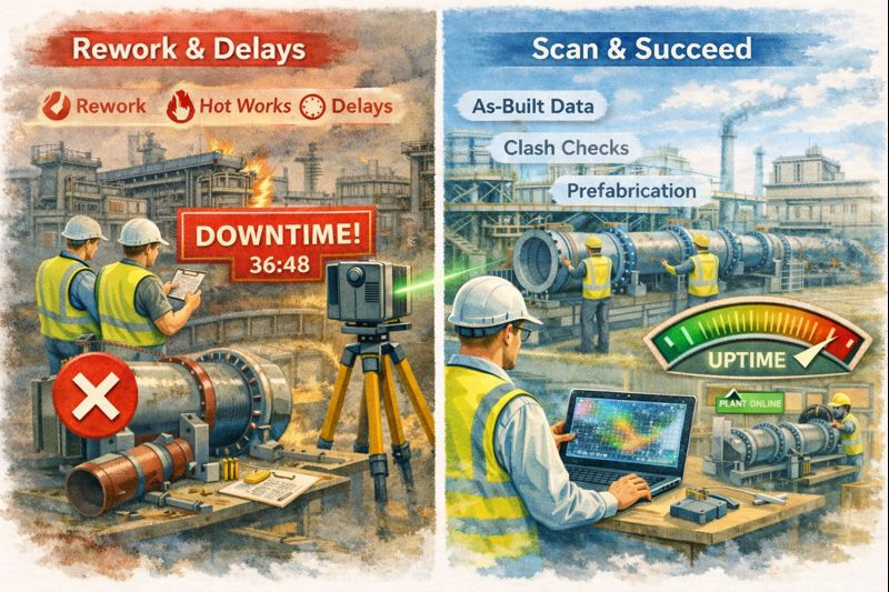
Reducing Fabrication Risk

Fabrication errors can become expensive when discovered during installation.

Typical causes of fabrication risk may include:

  • Missing dimensions
  • Incorrect assumptions
  • Clash issues
  • Existing condition inaccuracies
  • Poor fit-up

Engineering-grade scanning can support:

  • Existing condition verification
  • Improved design development
  • Clash detection
  • Better fabrication planning
  • Reduced site modifications

Identifying problems digitally generally costs less than discovering them during installation.

How Hamilton By Design Supports Reverse Engineering Projects

Hamilton By Design combines engineering experience with digital engineering workflows including:

  • Engineering-grade 3D LiDAR scanning
  • Existing condition capture
  • Scan-to-CAD workflows
  • CAD modelling
  • Engineering drawings
  • Engineering analysis and simulation
  • Fabrication documentation
  • Mechanical engineering services

Our workflows naturally support broader engineering services including:

  • 3D CAD Design & Drafting
  • Engineering Analysis & Simulation
  • Mining Mechanical Engineering
  • Engineering Documentation & Digital Engineering
  • Industrial Plant Optimisation
  • LiDAR Scanning Services
3D LiDAR scanning and 3D modelling service button โ€” laser scanner capturing a point cloud for engineering and CAD modelling
Mechanical engineering services

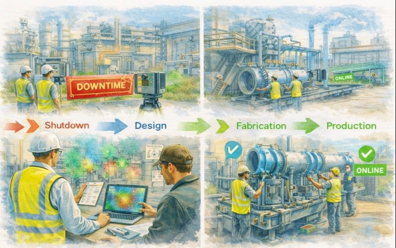
Moving Beyond Visual Models

Reverse engineering projects require more than attractive 3D models.

They require engineering information that supports:

  • Manufacturing
  • Installation
  • Reliability
  • Maintenance
  • Long-term asset management

Engineering-grade scanning helps transform physical assets into measurable engineering information that reduces risk and improves confidence in project outcomes.

Better information supports better engineering decisions.

Hamilton By Design logo displayed on a blue tilted rectangle with a grey gradient background

Our Clients:

Name
Would you like us to arrange a phone consultation for you?
Address

3D Engineering Scanning in Fiji โ€“ Reliable Point Clouds for Global Engineering

Engineer performing 3D laser scanning in Fiji with point cloud transforming into BIM model and FEA analysis beside a tropical port.

3D Engineering Scanning Fiji โ€“ Point Clouds for Design & FEA | Hamilton By Design

Hamilton By Design provides professional 3D laser scanning services across Fiji, delivering high-accuracy point clouds that allow designers, engineers, and asset owners anywhere in the world to work with real, measured dataโ€”without stepping foot on site.

Our focus is simple:
capture the truth of your asset once, and let every engineering discipline design from the same digital backbone.


Engineering-Grade Data You Can Design From

In Fiji, many industrial, marine, and commercial assets have:

  • incomplete or outdated drawings
  • decades of informal modifications
  • mixed construction standards
  • corrosion and cyclone damage history

Traditional measurement methods struggle in this environment. Our 3D scanning service produces a survey-accurate digital replica that can be used for:

  • 3D modelling in Revit, Plant3D, Tekla, SolidWorks
  • structural analysis and FEA studies
  • clash detection for new equipment
  • fabrication of steel and pipework
  • condition assessments and deformation checks

We deliver neutral, open formats so your teamโ€”anywhere in Australia, New Zealand, Fiji, or globallyโ€”can immediately begin engineering work.


What We Deliver

Core Outputs

  • Registered point clouds (E57 / RCP / LAS)
  • Colourised, engineering-accurate datasets
  • Site coordinate systems or project datum
  • Mesh models for Navisworks / visualisation
  • 2D plans, elevations, and sections

Optional Engineering Deliverables

  • Scan-to-BIM models (LOD 200โ€“350)
  • Steel and pipe geometry extraction
  • Tie-in coordinates for brownfields projects
  • Deformation and roundness reports
  • Clash and constructability reviews

Every dataset is processed in Australia under formal QA procedures so it can be relied upon for detailed design, certification, and FEA modelling.


Designed for Fiji Conditions

Scanning in Fiji requires more than equipmentโ€”it requires experience in Pacific environments.

We plan projects around:

  • tropical heat and humidity
  • sudden rain events
  • reflective stainless and bright sunlight
  • inter-island logistics
  • remote power and access constraints
  • cyclone season scheduling

Our workflows are built so field capture is efficient and robust, while processing and modelling are completed by our Australian engineering team.


Industries We Support in Fiji

  • Ports and wharves โ€“ Suva, Lautoka, Levuka
  • Power generation and utilities
  • Sugar and food processing plants
  • Water and wastewater infrastructure
  • Resorts and commercial buildings
  • Bridges and civil structures
  • Post-cyclone assessments
  • Mining and materials handling

A Digital Backbone for Global Teams

A quality scan is the backbone of every downstream task.
If the backbone is wrong, every model, drawing, and FEA result is compromised.

Our aim is to give your project a foundation that:

  • removes re-measure risk
  • allows off-site fabrication
  • supports remote engineering teams
  • shortens shutdowns
  • improves safety and constructability

Designers and engineers in any location can open our data and begin work immediatelyโ€”confident it represents the real world.

3D LiDAR scanning and 3D modelling service button โ€” laser scanner capturing a point cloud for engineering and CAD modelling
Mechanical engineering services

Hamilton By Design logo displayed on a blue tilted rectangle with a grey gradient background

Why Choose Hamilton By Design

  • Engineer-led scanning team
  • Australian processing and QA
  • experience in PNG and Pacific brownfields
  • deliverables tailored to your software
  • practical understanding of fabrication and FEA requirements

We donโ€™t just capture pointsโ€”we deliver usable engineering information.


Talk to Us About Your Fiji Project

Whether you need a single building, a wharf, or a full processing plant captured, we can mobilise quickly and provide data your global team can trust.

Hamilton By Design
Engineering certainty through 3D scanning.

Name
Would you like us to arrange a phone consultation for you?
Address

3D CAD Modelling Australia service banner for Hamilton By Design
Finite Element Analysis (FEA) engineering simulation button
Mechanical engineering services

Supporting Australian Coal โ€“ Engineering-Led 3D Scanning for CHPP & Coal Wash Plants

CHPP wash plant illustration comparing shutdown rework with LiDAR scanning and prefabrication success.

3D Scanning Services for CHPP โ€“ Reduce Rework, Maximise Uptime

Australian coal operations depend on reliable Coal Handling & Preparation Plants (CHPP), wash facilities, conveyors and mechanical systems. Every shutdown, upgrade and modification must be delivered quickly and safely to protect production. The most effective way to achieve this is through engineering-led 3D scanning services that capture real site conditions before a single component is fabricated.

Hamilton By Design specialises in FARO LiDAR and structured-light 3D scanning for the coal sector, turning complex brownfield sites into accurate digital models that drive practical engineering outcomes. Our focus is simple: maximise plant uptime by reducing rework.


Why Shutdowns Need Better Information

Coal wash plants are dynamic environments. Over decades of modifications:

  • drawings no longer match reality
  • structures move under load
  • pipe routes are altered
  • access becomes restricted

Relying on tape measures and sketches during a shutdown invites risk. A bracket that is 20 mm wrong or a spool that fouls an existing service can cost days of lost production. Accurate 3D scanning before the outage removes those unknowns.


Coal wash plant shutdown workflow from delays to scan-led success using LiDAR.

Hamilton By Design 3D Scanning Services

Our scanning services are built specifically for industrial and mining applications:

FARO LiDAR As-Built Capture

  • full plant and conveyor surveys
  • transfer stations, bins and pump boxes
  • structural steel and foundations
  • tie-in points for new pipework
  • clearance verification for maintenance

Structured-Light Scanning (EinScan)

  • motors, gearboxes and legacy parts
  • guards, covers and small assemblies
  • reverse engineering for obsolete components
  • detailed capture for first-time-fit design

Point Cloud to CAD Workflows

  • modelling in SolidWorks & Fusion
  • fabrication drawings for local workshops
  • clash detection and installation planning
  • digital twins for ongoing maintenance

These services ensure that design decisions are based on measured reality, not assumptions.


Engineering-led LiDAR scanning sequence from downtime to online restart.

FARO LiDAR for CHPP As-Builts

Terrestrial LiDAR creates a high-density point cloud of the entire coal wash facility. Engineers can:

  • design new chutes and spools directly over site geometry
  • confirm conveyor alignments
  • plan access platforms and walkways
  • test installation sequences digitally

By linking scanning to engineering, components arrive on site ready to install โ€” protecting uptime and reducing rework during critical shutdown windows.


Practical Outcomes for Coal Plants

Conveyor & Transfer Upgrades

  • accurate chute replacements
  • skirt and belt line verification
  • drive and pulley modifications
  • minimal site adjustments

Pump Boxes & Pipework

  • prefabricated spools that fit first time
  • reverse engineering of worn equipment
  • safe tie-ins without surprises

Structural & Access Works

  • platform and handrail retrofits
  • screen support modifications
  • crane and lifting planning

Every task is driven by 3D scan data so workshops fabricate with confidence.


Visual comparison of EinScan object scanner and LiDAR terrestrial laser scanner in matching sketch style.

Engineering-Led, Not Just Surveying

Hamilton By Design treats scanning as part of the engineering process:

  1. 3D capture of the live plant
  2. engineering review of critical datums
  3. point cloud modelling in parametric CAD
  4. fabrication drawings for Australian workshops
  5. shutdown planning to ensure first-time fit

This approach directly supports the goal of maximum plant uptime.


Supporting Australian Capability

Scan-driven design keeps work local. Regional fabricators receive accurate models and drawings that reflect the real CHPP environment, enabling:

  • faster workshop production
  • fewer site variations
  • safer installations
  • reduced dependence on imported components

Committed to the Coal Sector

Hamilton By Design supports coal operations across NSW, the Central Coast, Sydney and regional Queensland including Mount Isa. Our 3D scanning services enhance every stage of shutdown planning and brownfield upgrades by eliminating guesswork and cutting rework.


Hamilton By Design logo displayed on a blue tilted rectangle with a grey gradient background
3D LiDAR scanning and 3D modelling service button โ€” laser scanner capturing a point cloud for engineering and CAD modelling
Mechanical engineering services

Our Services

  • FARO LiDAR scanning for CHPP as-builts
  • EinScan component capture
  • Point cloud to CAD modelling
  • Fabrication drawings & DXF outputs
  • Clash detection and digital twin support

Maximise your plant uptime by reducing rework โ€” talk to us before your next shutdown.

Name
Would you like us to arrange a phone consultation for you?
Address

3D CAD Modelling Australia service banner for Hamilton By Design
Finite Element Analysis (FEA) engineering simulation button
Mechanical engineering services

Engineering-Led 3D Scanning for Inner West Sydney Refurbishments

Engineer and client reviewing 3D laser scan data inside an Inner West Sydney heritage building with ANZAC Bridge and Sydney Fish Market in the background.

Refineries, Heritage Buildings & Industrial Retrofits Done Right

The Inner West of Sydney is home to some of the cityโ€™s most complex refurbishment environments.
From legacy refinery and industrial sites through to heritage-listed warehouses, factories, and commercial buildings, these assets were never designed with modern codes, loading requirements, or services in mind.

Yet today, theyโ€™re being asked to support:

  • New plant and equipment
  • Adaptive re-use and change of occupancy
  • Heavier floor loads
  • Updated fire, seismic, and structural standards
  • Modern services routing in very old structures

This is where many refurbishment projects run into trouble โ€” not because the design is poor, but because the starting information is wrong or incomplete.


The Inner West Problem: Old Buildings, New Standards

Much of the Inner Westโ€™s industrial and heritage building stock was constructed:

  • Under superseded Australian Standards
  • With unknown material properties
  • Using construction methods no longer permitted
  • With undocumented modifications over decades of use

What often looks acceptable visually may be:

  • Structurally marginal under modern load cases
  • Locally compromised due to corrosion, settlement, or fatigue
  • Modified in ways that no longer match original drawings

When these issues are discovered late in the design process, the outcome is almost always the same:

  • Redesign
  • Strengthening
  • Programme delays
  • Budget escalation

Engineering-led 3D scanning of an existing Inner West Sydney industrial building prior to refurbishment and structural assessment.

Why Waiting Until โ€œDetailed Designโ€ Is Too Late

A common scenario we see in Inner West refurbishments:

  1. Concept design proceeds based on legacy drawings or assumptions
  2. Floor layouts, equipment, and architectural intent are developed
  3. Engineering review begins
  4. Structural checks identify:
    • Inadequate floor capacity
    • Unsupported penetrations
    • Changed load paths
    • Degraded or altered members
  5. Design is forced to change โ€” often significantly

At this point, the engineer isnโ€™t blocking creativity โ€” theyโ€™re responding to reality.

The issue isnโ€™t engineering input.
The issue is when the true condition of the structure becomes visible.


Start With a Scan: Let Designers Create With Confidence

Engineering-grade 3D laser scanning at the very beginning of a refurbishment changes the entire dynamic of a project.

Instead of reacting to unknowns later, the project team starts with:

  • Verified geometry
  • True floor levels and deflection
  • Structural alignment and deformation
  • Accurate column, beam, and slab positions
  • Measured deviations from original drawings

This gives architects and designers something powerful:

Freedom to design within known constraints โ€” not guessed ones.


Heritage & Industrial Retrofits: Why Scanning Matters Even More

Heritage Buildings

Heritage structures often prohibit invasive investigation early on.
3D scanning allows:

  • Non-intrusive verification of geometry
  • Identification of movement or deformation
  • Assessment of tolerance drift over time
  • Planning of sympathetic strengthening solutions

Refineries & Legacy Industrial Sites

Inner West refinery and process facilities bring additional challenges:

  • Tight access
  • Live plant interfaces
  • Safety-critical environments
  • Brownfield congestion

Scanning provides:

  • Safe remote measurement
  • Clash-free retrofit design
  • Confidence before shutdowns
  • Reduced rework during construction

When Standards Change, Reality Matters

One of the most common late-stage surprises in refurbishments is floor capacity.

Buildings that performed adequately for decades may no longer comply with:

  • Current live load requirements
  • Change-of-use provisions
  • Equipment point loads
  • Modern safety factors

Without accurate structural geometry and context, engineers are forced to:

  • Assume worst-case scenarios
  • Over-design strengthening
  • Restrict layouts unnecessarily

Early scanning supports informed engineering judgement, often resulting in:

  • Targeted strengthening instead of blanket solutions
  • Retention of original fabric where possible
  • Reduced material and construction costs

Blue banner graphic displaying the text "Point Cloud to CAD - Australia" in large white lettering, representing point cloud processing, scan-to-CAD conversion and digital engineering services across Australia.
Blue banner graphic displaying the text "Scan to CAD Sydney" in large white lettering, representing engineering-led point cloud to CAD conversion, LiDAR scanning and digital engineering services in Sydney.
Blue banner graphic displaying the text "Reality Capture Sydney - CBD" in large white lettering, representing engineering-led reality capture, LiDAR scanning and digital engineering services within Sydney CBD commercial buildings and infrastructure.

From Point Cloud to Engineering Decisions

At Hamilton By Design, scanning is not a standalone service โ€” itโ€™s an engineering tool.

Our process typically supports:

  • Structural verification of existing buildings
  • Floor flatness, level, and deflection assessment
  • Alignment checks of columns and frames
  • Scan-to-CAD models for design integration
  • Fit-for-purpose information for refurbishment decisions

This is especially critical in Inner West projects, where:

  • Every millimetre matters
  • Access is limited
  • Heritage considerations are real
  • Late changes are costly

Design With Knowledge, Not Surprises

Refurbishments donโ€™t fail because buildings are old.
They fail because assumptions survive too long.

By starting with an engineering-led scan:

  • Designers get space to create
  • Engineers get data they can trust
  • Asset owners avoid late-stage shocks
  • Projects move forward with confidence

If youโ€™re planning a refinery upgrade, heritage refurbishment, or adaptive re-use project in Inner West Sydney, the smartest decision you can make is to scan first โ€” before concept becomes constraint.


Thinking about a refurbishment or retrofit in the Inner West?

Engineering-grade 3D scanning at the start gives your project clarity, confidence, and creative freedom โ€” not limitations.

3D LiDAR scanning and 3D modelling service button โ€” laser scanner capturing a point cloud for engineering and CAD modelling
Mechanical engineering services
Name
Would you like us to arrange a phone consultation for you?
Address
3D CAD Modelling Australia service banner for Hamilton By Design

How AS 1100 and LiDAR Scanning Work Together: From Point Cloud to Compliant Drawings

Graduate engineer and senior engineer using LiDAR scanning on a Parramatta River construction site, reviewing point cloud data for accurate design.

AS 1100 & LiDAR Scanning: Compliant Engineering Drawings from Point Clouds

If youโ€™ve ever tried to update old plant drawings, verify a brownfield tie-in, or issue โ€œas-builtโ€ documentation after a shutdown, youโ€™ll know the pain: the site never matches the drawings, access is limited, and the smallest dimensional miss can cascade into rework, clashes, and schedule blowouts.

Thatโ€™s where engineering-grade LiDAR scanning and AS 1100 (the Australian Standard for technical drawing) make a powerful combination. LiDAR gives you truth data (reality capture), and AS 1100 gives you a shared language for turning that truth into clear, consistent, contract-ready documentation.

At Hamilton By Design, we treat scanning and drawing as one joined workflow: capture accurately โ†’ model intelligently โ†’ document to AS 1100 so everyone downstream can build, fabricate, install, and sign off with confidence.
(If you want to see the service side of this workflow, start here: https://www.hamiltonbydesign.com.au/home/engineering-services/3d-laser-scanning/3d-laser-scanning-for-engineering-projects/ and here: https://www.hamiltonbydesign.com.au/home/3d-lidar-scanning-digital-quality-assurance/)


What AS 1100 actually โ€œdoesโ€ in the real world

AS 1100 standardises the way we communicate engineering information through drawings: layout, line types, projection methods, dimensioning rules, tolerancing conventions, symbols, notes, and drawing presentation.

In practice, AS 1100 helps you answer questions like:

  • Which edges are visible vs hidden? (line conventions)
  • How are views arranged and interpreted? (projection and view layout)
  • How do we dimension so the fabricator canโ€™t misread it? (dimensioning rules)
  • How do we document what matters vs whatโ€™s โ€œreference onlyโ€? (notes and drawing hierarchy)
  • How do we keep drawing sets consistent across multiple contributors? (formatting + standards)

That consistency is exactly whatโ€™s needed after a scanโ€”because point clouds are rich, but theyโ€™re not automatically โ€œcommunicableโ€ in the way a compliant drawing set is.


What LiDAR scanning adds that drawings alone canโ€™t

A LiDAR scanner captures millions (often billions) of spatial points that represent real surfacesโ€”steel, concrete, pipe, equipment, structureโ€”creating a point cloud that can be registered into a unified coordinate system.

Dassault Systรจmes SolidWorks Professional Weldments certification badge

In the engineering context, the big advantages are:

  • Speed: capture complex geometry quickly, often with minimal disruption
  • Coverage: see whatโ€™s hard to measure with tape/total station (overhead services, congested pipe racks, odd geometry)
  • Context: capture โ€œeverything,โ€ not just what someone remembered to measure
  • Traceability: you can always โ€œgo backโ€ to the scan for verification and queries
  • Clash prevention: scan-to-CAD makes it far easier to design upgrades that actually fit

But hereโ€™s the key: a point cloud isnโ€™t a deliverable most trades can fabricate from directly.
Thatโ€™s why AS 1100 becomes the bridge between capture and construction.


The combined workflow: Point cloud โ†’ model โ†’ AS 1100 drawings

1) Capture the site as it really is

We scan the area of interest and register scans into a coordinated dataset. This becomes the base truth for everything that follows. If the project is shutdown-driven, we plan scanning around access windows and risk controls (often capturing adjacent tie-in zones too, because โ€œnearbyโ€ services are where surprises live).

2) Establish intent: โ€œWhat are we delivering?โ€

Not every project needs the same output. Typical outcomes include:

  • As-built drawings for existing assets
  • As-found models to support new design work
  • Dimensional verification for fit-up and prefabrication
  • Digital QA against design intent (scan-vs-model comparison)

Hamilton By Design leans hard into this QA piece where it matters mostโ€”because catching a misalignment early is cheaper than discovering it on install day.
More on the QA angle here: https://www.hamiltonbydesign.com.au/home/3d-lidar-scanning-digital-quality-assurance/

3) Convert scan data into engineering geometry (as much as needed)

Sometimes the best output is a controlled 3D model (plant layout, pipe spools, structural members). Other times the project is best served by 2D drawings extracted from a model.

Weโ€™ll typically create:

  • key datums and grids
  • primary steel / structure
  • equipment envelopes and critical interfaces
  • piping runs and connection points (where relevant)
  • floor levels, platforms, access constraints, clearance zones

4) Document to AS 1100 so the drawing set is unambiguous

This is where AS 1100 shines. We turn geometry into drawings that read cleanly and consistently across teams.

That includes:

  • correct view layouts (plan/elevation/section/detail)
  • line conventions (visible/hidden/centre lines)
  • clear dimensioning strategy (functional dims first)
  • consistent annotation and notes
  • drawing borders, title blocks, revision control, and drawing register discipline

In short: LiDAR gives accuracy, AS 1100 gives clarity.


Where AS 1100 + LiDAR scanning delivers immediate value

Brownfield upgrades and tie-ins

Tie-ins fail when the โ€œas-builtโ€ condition is wrong. A scan gives you real geometry; AS 1100 drawings package it so designers, fabricators, and installers share the same reference. This is especially useful when multiple contractors are interfacing.

Fabrication and spool accuracy

If youโ€™re fabricating offsite (pipe spools, platform steel, handrail sections, ducting), you need dependable dimensions and an agreed drawing language. Scan-derived models support accuracy; AS 1100 drawings support fabrication interpretation and QA sign-off.

Shutdown planning and constructability

A point cloud is a brilliant planning toolโ€”access routes, crane clearances, removal paths, temporary works, and โ€œwhatโ€™s in the way.โ€ But shutdown packages still need compliant drawings for permits, isolations, install workpacks, and handover packs. AS 1100 keeps those packages readable and defensible.

Verification and โ€œwhat changed?โ€

Sites evolve. A scan provides a timestamped snapshot. Drawings updated to AS 1100 become the controlled record: what was there, what was installed, and what the current state is. That matters for maintenance, safety, and future projects.


Practical example: Turning a congested pipe rack into a buildable upgrade

Imagine youโ€™re adding a new line through an existing pipe rack:

  1. Scan the rack to capture all existing services, supports, cable trays, and steel
  2. Model critical geometry (existing plus proposed) to check routing and supports
  3. Clash check before fabrication begins
  4. Issue AS 1100 drawings for:
    • support details
    • spool isometrics (if applicable)
    • arrangement drawings showing tie-in locations
    • sections through congestion zones
    • installation notes and tolerances where appropriate
  5. Verify post-install with a follow-up scan if required for QA/closeout

Thatโ€™s the โ€œwork togetherโ€ part: the scan stops guesswork, and AS 1100 stops misinterpretation.


Common mistakes when scanning isnโ€™t tied back to AS 1100

  • Delivering point clouds without a drawing strategy (stakeholders canโ€™t use them effectively)
  • Over-modelling everything (time is spent modelling non-critical items instead of delivering useful documentation)
  • Unclear dimensioning (scan accuracy is wasted if dimensions are presented ambiguously)
  • No controlled datums (people argue about โ€œwhere zero isโ€ and models drift between disciplines)
  • Weak revision control (the drawing set becomes untrustworthy fast)

A standards-led drawing approach prevents most of these.


How we approach it at Hamilton By Design

Our angle is simple: engineering-led scanningโ€”not scanning for its own sake.

  • We capture reality with LiDAR.
  • We translate it into the level of model detail the project actually needs.
  • We document outputs with the discipline and consistency expected in Australian engineering environments.

If you want the practical breakdown of how we do scan capture and modelling for projects, start here:
https://www.hamiltonbydesign.com.au/home/engineering-services/3d-laser-scanning/3d-laser-scanning-for-engineering-projects/

And if your priority is dimensional verification, fit-up confidence, or proving compliance against design intent, this page explains our digital QA approach:
https://www.hamiltonbydesign.com.au/home/3d-lidar-scanning-digital-quality-assurance/


Hamilton By Design logo displayed on a blue tilted rectangle with a grey gradient background

Closing thought: accuracy is only valuable if itโ€™s understandable

LiDAR scanning can deliver millimetre-grade spatial truth. But in real projects, truth still has to travel through peopleโ€”engineers, drafters, fabricators, installers, supervisors, and asset owners.

AS 1100 makes that truth readable.
LiDAR makes it reliable.

3D LiDAR scanning and 3D modelling service button โ€” laser scanner capturing a point cloud for engineering and CAD modelling
Mechanical engineering services

Together, they turn messy real-world geometry into clear, controlled documentation that supports safer installs, faster shutdowns, and fewer surprises.

Name
Would you like us to arrange a phone consultation for you?
Address

3D Laser Scanning on the Central Coast NSW: From Point Cloud to Build-Ready CAD

From laser scan to CAD: point cloud of Avoca Beach foreshore assets converted into build-ready engineering drawings.

Accurate site data is the difference between a smooth upgrade and a shutdown full of surprises.
At Hamilton By Design, we provide engineering-grade 3D laser scanning (LiDAR) across the Central Coast NSW โ€” including Wyong, Gosford, Tuggerah and Somersby โ€” and convert that data into design-ready CAD and 3D models for industrial and building projects.

If youโ€™re planning equipment upgrades, new conveyors, structural modifications or fabrication packages, scanning gives you reliable geometry before steel is cut or contractors mobilise.


Who this service is for

Our Central Coast scanning services are typically used by:

  • Project engineers planning plant or building upgrades
  • Maintenance teams preparing shutdown scopes
  • Fabricators needing accurate tie-in dimensions
  • Asset owners updating as-built records
  • Consultants managing brownfield modifications

If drawings donโ€™t match reality โ€” or donโ€™t exist at all โ€” scanning becomes the safest and fastest way to establish an accurate baseline.


3D LiDAR scanning services on the Central Coast providing engineering-grade laser scanning, point cloud capture, scan-to-CAD modelling and industrial reality capture for infrastructure and industrial projects.
Drafting services on the Central Coast providing engineering drawings, fabrication detailing, as-built documentation, reverse engineering and CAD drafting for industrial and infrastructure projects.
Mechanical engineering services on the Central Coast providing industrial design, plant inspections, pump calculations, reverse engineering and engineering support for manufacturing, infrastructure and heavy industry projects.

From scan to CAD: turning site data into buildable designs

A point cloud on its own doesnโ€™t solve project risk.
What matters is converting scan data into usable engineering outputs.

Our workflow supports:

  • 2D CAD drawings (plans, sections, elevations)
  • 3D CAD models for layout and clash detection
  • Tie-in modelling for new equipment and structures
  • Verification of clearances and access zones
  • Fabrication-ready geometry for workshop drawings

This scan-to-CAD process is especially valuable for retrofit projects where new components must integrate with existing assets.


Why 3D scanning is ideal for brownfield upgrades

Most Central Coast industrial and commercial sites are brownfield environments โ€” tight access, legacy equipment and undocumented modifications.

3D laser scanning helps to:

  • Reduce site re-visits and manual re-measuring
  • Identify clashes early in the design phase
  • Support off-site prefabrication
  • Shorten shutdown windows
  • Improve safety by limiting exposure time on site

When combined with engineering design, scanning becomes a risk-reduction tool, not just a survey method.


Engineer using 3D laser scanner at Avoca Beach foreshore with point cloud and CAD model showing upgrade of coastal stairs and seawall.

Typical Central Coast applications

We regularly support projects across:

Manufacturing and processing facilities

Equipment replacements, conveyor upgrades, access platform modifications.

Warehousing and logistics buildings

Structural modifications, mezzanine installations, services coordination.

Building services upgrades

Plantroom retrofits, mechanical services coordination, compliance verification.

Mining-related fabrication and off-site packages

Where Central Coast workshops are producing components for remote sites.


Local coverage: Wyong, Gosford, Tuggerah and Somersby

Being based on the Central Coast means we can support:

  • Rapid site capture
  • Staged scanning across multiple areas
  • Follow-up verification scans as scope evolves

That flexibility is important when designs change during live projects or shutdown preparation.


How accurate is engineering-grade LiDAR scanning?

Accuracy depends on site conditions and scope, but scanning provides consistent, repeatable geometry across complex environments that would be difficult and time-consuming to measure manually.

More importantly, it captures:

  • Spatial relationships
  • Real clearances
  • True equipment alignment

which are critical for retrofit engineering and fabrication.


When is scanning worth the investment?

Scanning typically delivers the best value when:

  • Drawings are outdated or incomplete
  • Fabrication must fit first time
  • Shutdown time is expensive
  • Access is restricted or unsafe
  • Multiple trades must coordinate in tight spaces

In many projects, preventing one major clash or rework cycle pays for the scan many times over.


Hamilton By Design logo displayed on a blue tilted rectangle with a grey gradient background

3D LiDAR scanning and 3D modelling service button โ€” laser scanner capturing a point cloud for engineering and CAD modelling
Mechanical engineering services

Planning an upgrade or fabrication project on the Central Coast?

If youโ€™re preparing for a shutdown, equipment upgrade or fabrication package across the Central Coast, early scanning can significantly reduce downstream risk.

Talk to Hamilton By Design about 3D laser scanning and point cloud to CAD support for your project.
Weโ€™ll help define the scope and deliverables that best suit your engineering and construction needs.

Name
Would you like us to arrange a phone consultation for you?
Address