Terrestrial LiDAR Scanner | Engineering-Grade 3D Laser Scanning

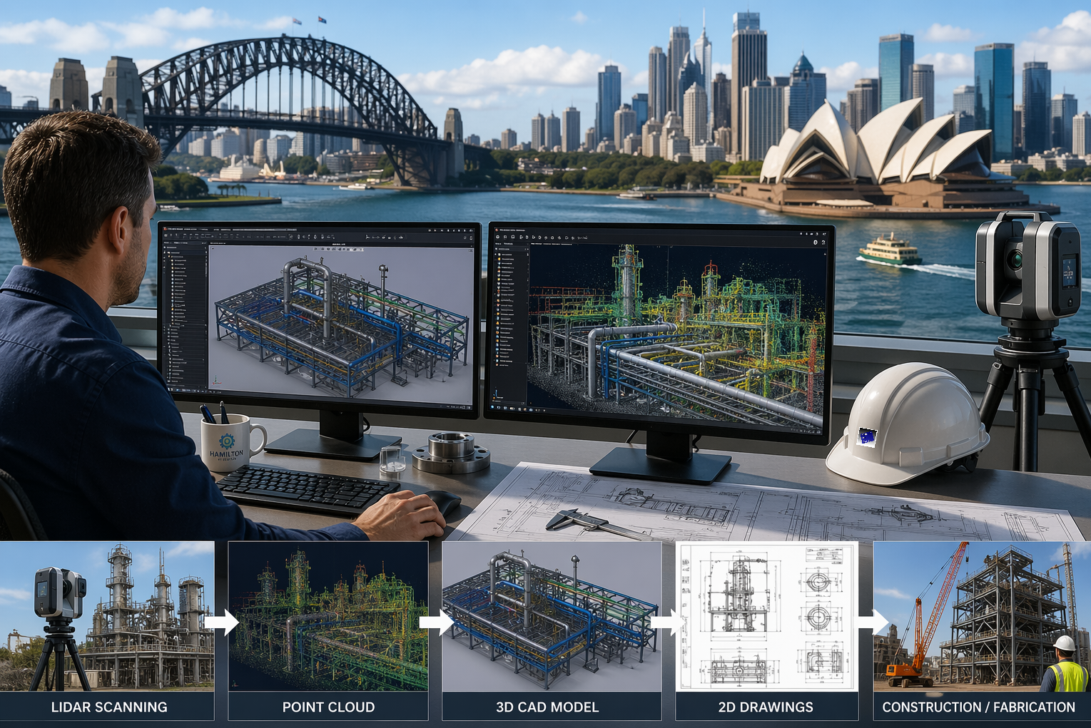
Terrestrial LiDAR scanner capturing industrial plant

What is a Terrestrial LiDAR Scanner?

A terrestrial LiDAR scanner is a ground-based 3D laser scanning system used to capture highly accurate measurements of real-world environments and convert them into detailed digital models known as point clouds.

At Hamilton By Design, we use engineering-grade terrestrial LiDAR scanning to support design, drafting, and construction across industrial, mining, and infrastructure projects.

3D LiDAR scanning and 3D modelling service button โ€” laser scanner capturing a point cloud for engineering and CAD modelling
Mechanical engineering services

How a Terrestrial LiDAR Scanner Works

A terrestrial LiDAR scanner measures distance using laser technology:

  • A laser beam is emitted from the scanner
  • The beam reflects off surfaces such as steel, concrete, or pipework
  • The scanner records the return signal
  • Distance is calculated using time-of-flight or phase shift
  • Millions of measurements are captured per second

The result is a dense and accurate 3D point cloud representing the scanned environment.


What is a Point Cloud?

A point cloud is a digital dataset made up of millions (or billions) of points.

Each point contains:

  • X, Y, Z coordinates
  • Spatial position in 3D space
  • Optional colour information (RGB)

This creates a true-to-life digital representation of physical assets, forming the foundation for CAD modelling and engineering design.


Why Use a Terrestrial LiDAR Scanner?

Accuracy

Terrestrial LiDAR scanners provide millimetre-level accuracy, making them suitable for engineering and fabrication.

Speed

Large and complex environments can be captured quickly compared to traditional survey methods.

Safety

Data can be captured without direct access to hazardous or difficult-to-reach areas.

Reduced Rework

Designs are based on real-world data, reducing clashes and site modifications.

3D CAD Modelling Australia service banner for Hamilton By Design

Engineering Applications

Terrestrial LiDAR scanning is widely used across:

  • Industrial plant upgrades
  • Mining and processing facilities
  • Structural and mechanical design
  • Brownfield engineering projects
  • As-built verification
  • Reverse engineering

For projects requiring integration with your team, this capability can also be delivered through our engineering secondment services:
https://www.hamiltonbydesign.com.au/home/secondment-services/


Engineering-Led LiDAR Scanning

Not all LiDAR scanning is equal.

At Hamilton By Design, scanning is performed with an engineering-first approach, ensuring the data is suitable for downstream use in CAD and design.

Key considerations include:

  • Line-of-sight limitations
  • Scan density and coverage
  • Registration accuracy
  • Data structure and usability

This ensures the output is not just a visual model, but a usable engineering dataset.


From Scan to CAD

Our workflow converts LiDAR data into practical deliverables:

Scan โ†’ Register โ†’ Model โ†’ Detail โ†’ Deliver

This includes:

  • Point cloud registration (.E57, .RCP, .LAS)
  • 3D CAD modelling (SolidWorks and other platforms)
  • 2D drawings and fabrication-ready documentation

Terrestrial vs Other Scanning Methods

  • Terrestrial LiDAR: High accuracy, long range, ideal for engineering
  • Handheld scanners: Faster but lower accuracy, suited to small objects
  • Photogrammetry: Visual models, not typically engineering-grade

For industrial and brownfield environments, terrestrial LiDAR remains the preferred method.


Terrestrial LiDAR scanner capturing industrial plant with Sydney Harbour Bridge in background

In-House & Secondment Delivery

We provide flexible delivery models to suit your project:

  • In-house scanning and modelling (fully managed)
  • Secondment services (embedded within your team)

Learn more about our secondment capability:
https://www.hamiltonbydesign.com.au/home/secondment-services/


Why Choose Hamilton By Design

  • Engineering-led LiDAR scanning
  • Integration with CAD modelling and drafting
  • Strong experience in industrial and mining environments
  • Brownfield project expertise
  • Practical, buildable outputs

Hamilton By Design logo displayed on a blue tilted rectangle with a grey gradient background

Get Started with Terrestrial LiDAR Scanning

If you require accurate, engineering-grade 3D data for your project, a terrestrial LiDAR scanner provides the foundation for reliable design and execution.

Hamilton By Design delivers scanning, modelling, and engineering support across Sydney and Australia.
Talk to Us – Contact Us

Name
Would you like us to arrange a phone consultation for you?
Address

Mechanical Engineering | Structural Engineering


CAD Services Sydney | In-House & Secondment Engineering Support

Engineer developing 3D CAD model from LiDAR point cloud data with Sydney Harbour in background

Professional CAD Services in Sydney

When it comes to CAD services in Sydney, the difference is not just capability โ€” itโ€™s how that capability is delivered.

At Hamilton By Design, we provide both:

  • In-house CAD services (fully managed delivery)
  • Secondment CAD services (embedded within your team)

This gives you the flexibility to choose the right approach for your project โ€” whether you need a complete outsourced solution or direct support within your team.


3D LiDAR scanning and 3D modelling service button โ€” laser scanner capturing a point cloud for engineering and CAD modelling
Mechanical engineering services

In-House CAD Services (Fully Managed Delivery)

Our in-house CAD services are designed to deliver complete, end-to-end outcomes.

We manage:

  • Scope definition
  • CAD modelling and drafting
  • Engineering review and quality control
  • Final deliverables ready for fabrication or construction

This approach is ideal for:

  • Defined project scopes
  • Drawing packages
  • Scan-to-CAD modelling
  • Brownfield upgrades with clear deliverables

Secondment CAD Services (Embedded Support)

For projects requiring closer collaboration, we offer Secondment Services:
https://www.hamiltonbydesign.com.au/home/secondment-services/

This allows our engineers and designers to:

  • Work directly within your systems and processes
  • Integrate with your project teams
  • Support shutdowns and peak workloads
  • Provide continuity across design and execution

Secondment is ideal for:

  • Long-term projects
  • Multi-vendor environments
  • Ongoing plant upgrades
  • Internal resource gaps

3D CAD Modelling Australia service banner for Hamilton By Design

Engineering-Led CAD โ€” Not Just Drafting

Whether delivered in-house or through secondment, our CAD services are always engineering-led.

We focus on:

  • Constructability
  • Real-world constraints
  • Alignment with Australian standards
  • Practical, buildable outcomes

Our CAD Services in Sydney

2D Drafting & Drawing Development

  • General Arrangement (GA) drawings
  • Layout drawings for engineering proposals
  • Sections, elevations, and details
  • Drawing revisions and updates

3D CAD Modelling

  • SolidWorks mechanical modelling
  • Plant and equipment modelling
  • Structural and pipework modelling
  • Simplified coordination models

Point Cloud to CAD (Scan-to-Model)

  • Conversion of LiDAR scans (.E57, .RCP, .LAS)
  • Accurate as-built modelling
  • Critical for brownfield and retrofit projects

Built for Brownfield Projects

Sydney projects are typically brownfield, not greenfield.

We specialise in:

  • Retrofit design
  • Existing plant modifications
  • Clearance verification
  • Working with incomplete or outdated drawings

Delivery can be:

  • Fully managed in-house, or
  • Supported through secondment

LiDAR Scanning Integration

Our CAD services integrate with engineering-grade LiDAR scanning, ensuring designs are based on real-world data rather than assumptions.

This results in:

  • Accurate as-built models
  • Reduced rework
  • Improved design confidence

Drawing Control & Engineering Governance

We also support:

  • Revision control (IFR / IFA / IFC)
  • Drawing registers and version tracking
  • Cloud-based access via 3DEXPERIENCE
  • 24/7 access to current drawings

This can be delivered as a managed service or integrated through secondment.


From Scan to Fabrication

Our workflow:

Scan โ†’ Model โ†’ Detail โ†’ Review โ†’ Build

Delivered either:

  • In-house by our team, or
  • Embedded within your team via secondment

Get Started with CAD Services in Sydney

Whether you need:

  • A complete CAD package
  • Additional resources embedded in your team
  • Or a hybrid approach

Hamilton By Design delivers flexible, engineering-driven CAD services in Sydney.

Learn more about our Secondment Services:

Our clients

Talk to Us – Contact Us

Name
Would you like us to arrange a phone consultation for you?
Address
3D Scanning Sydney banner promoting engineering-grade 3D laser scanning, LiDAR scanning, and reality capture services by Hamilton By Design.
Mechanical Engineering Sydney banner with white text on a blue background representing Hamilton By Design's mechanical engineering services in Sydney.
Mechanical Drafting and 3D Modelling Sydney banner highlighting Hamilton By Design's CAD drafting, 3D modelling, and engineering design services in Sydney.


Mechanical Engineering | Structural Engineering


Hamilton By Design provides engineering-led 3D scanning, LiDAR scanning, mechanical engineering and digital engineering services throughout Sydney and Greater Sydney.

Explore our related Sydney services:


  • 3D Scanning Sydney โ€“ Engineering-grade terrestrial laser scanning, as-built surveys and point cloud capture for industrial, infrastructure and commercial projects.
  • Reality Capture Sydney โ€“ High-accuracy reality capture, digital twins, asset documentation and engineering-grade site verification.
  • Scan to CAD Sydney โ€“ Convert point cloud data into AutoCAD, SolidWorks, Inventor and other engineering-ready CAD deliverables.
  • Point Cloud Modelling Sydney โ€“ Engineering-grade point cloud processing, clash detection, as-built verification and 3D modelling.
  • Mechanical Engineering Sydney โ€“ Mechanical design, plant upgrades, materials handling systems, conveyors, chutes, platforms and engineering support.
  • Structural Drafting Sydney โ€“ Structural steel drafting, fabrication drawings, GA drawings, workshop detailing and as-built documentation.

Hamilton By Design supports projects throughout Sydney CBD, Parramatta, Liverpool, Penrith, Blacktown, Chatswood, Alexandria, Mascot, Newcastle and the Central Coast.


Blue banner graphic displaying the text "Point Cloud to CAD - Australia" in large white lettering, representing point cloud processing, scan-to-CAD conversion and digital engineering services across Australia.
Blue banner graphic displaying the text "Scan to CAD Sydney" in large white lettering, representing engineering-led point cloud to CAD conversion, LiDAR scanning and digital engineering services in Sydney.

Blue banner graphic displaying the text "Reality Capture Sydney - CBD" in large white lettering, representing engineering-led reality capture, LiDAR scanning and digital engineering services within Sydney CBD commercial buildings and infrastructure.

Brownfield Costโ€“Benefit: Engineering Design vs Continuous Navisworks Model Maintenance

Executive Summary

In brownfield projects, the highest return comes from applying engineering design effort at the point of change, supported by accurate point cloud data, rather than continuously updating a federated model.

The practical reality is:

Invest in engineering decisions, not in maintaining a model that becomes outdated faster than the plant changes.


3D LiDAR scanning and 3D modelling service button โ€” laser scanner capturing a point cloud for engineering and CAD modelling
Mechanical engineering services

Two Approaches

1. Model Maintenanceโ€“Centric (Navisworks)

Using Autodesk Navisworks Manage as an ongoing platform:

  • Maintain a full federated model
  • Update after every site change
  • Re-run coordination and clash detection
  • Manage model alignment across disciplines

2. Engineering-Driven (Point Cloud + Targeted CAD)

Using:

  • FARO SCENE
  • SOLIDWORKS eDrawings
  • Capture and retain point cloud data as the primary asset
  • Model only what is being modified
  • Use CAD and drawings for fabrication and communication

Cost Drivers

Navisworks Model Maintenance

  • Initial model creation and federation
  • Continuous updates after modifications
  • Data conversion and reprocessing
  • Coordination meetings and clash resolution
  • Ongoing QA and model validation

Additional hidden costs include:

  • Model drift corrections
  • Rework due to mismatch with site conditions
  • Reliance on a limited number of trained users

Engineering-Driven Workflow

  • Targeted scanning where required
  • Point cloud processing and validation
  • Engineering design effort for modifications
  • Drawing and component model production

Additional benefits include:

  • Reusable scan data
  • No requirement to maintain a full plant model
  • Faster response to site-driven changes

3D CAD Modelling Australia service banner for Hamilton By Design

Benefit Comparison

Navisworks model maintenance offers strong upfront coordination, particularly in greenfield projects, but suffers from degradation over time and high ongoing cost.

Engineering-driven workflows using point cloud data provide higher long-term accuracy, faster turnaround for small changes, and better alignment with real site conditions.


Line-of-Sight Reality

Point cloud data is inherently line-of-sight dependent. This means:

  • Only visible surfaces are captured
  • Occlusions result in gaps in the dataset

This limitation exists regardless of software platform.

Importing a point cloud into Navisworks does not improve data completeness or accuracy โ€” it simply presents the same data in a different environment.


Practical Example

For a minor electrical upgrade:

Navisworks Approach

  • Update the federated model
  • Re-run coordination
  • Issue revised model
  • Proceed with installation

This introduces significant overhead for a simple task.


Engineering Approach

  • Review point cloud or site conditions
  • Confirm clearances
  • Design locally
  • Install
  • Update drawings if required

This approach is faster, lower cost, and aligned with how work is actually executed.


Where Navisworks Adds Value

Navisworks remains effective when:

  • Multiple disciplines are designing simultaneously
  • Large-scale coordination is required
  • Clash detection is critical

This typically applies to:

  • Greenfield projects
  • Major brownfield upgrades

It should be treated as a project-phase coordination tool, not a long-term data management system.


  • Use point cloud data as the primary reference
  • Maintain raw and registered datasets (e.g. E57)
  • Model only critical interfaces and new work
  • Use drawings for formal deliverables
  • Apply Navisworks selectively where coordination is required

Final Position

In brownfield environments, value is created through engineering design and decision-making, not through continuous model maintenance.


One-Line Summary

Design what youโ€™re changing. Scan what youโ€™re keeping. Donโ€™t model what you wonโ€™t maintain.

Our clients

Talk to Us – Contact Us

Name
Would you like us to arrange a phone consultation for you?
Address
CHPP Engineering title graphic featuring bold white text reading "CHPP Engineering" centred on a blue rounded rectangle background.
Pipework Drafting title graphic featuring bold white text reading "Pipework Drafting" centred on a blue rounded rectangle background.
3D LiDAR Scanning for Engineering Projects title graphic featuring bold white text on a blue rounded rectangle background.

Brownfield Project Management

Brownfield industrial plant point cloud compared to clean Navisworks model showing real-world conditions versus design coordination

The Reality of Brownfield Development – Brownfield Project Management: Why Point Cloud Data Should Not Be Managed in Navisworks

Brownfield projects are not clean, linear, or model-driven.

They are:

  • Reactive
  • Incremental
  • Constrained by existing infrastructure
  • Driven by time, cost, and operational pressure

In this environment, the idea of maintaining a fully coordinated 3D model is often unrealistic.

A simple example illustrates this:

An electrician installs an additional power point on site. The work is completed, energised, and signed off. The drawings may be updated later โ€” the model almost never is.

This is not a failure of process โ€” it is the reality of brownfield operations.


3D LiDAR scanning and 3D modelling service button โ€” laser scanner capturing a point cloud for engineering and CAD modelling
Mechanical engineering services

Engineering Reality: From Sketch to CAD

Before anything becomes a 3D model, it starts much simpler.

As engineers, we still:

  • Sketch ideas
  • Mark up drawings
  • Discuss constraints on site

Only after this thinking process do concepts become CAD models.

This reinforces a key principle:

Engineering decisions are not driven by software โ€” software supports engineering judgement.


The Problem with Model-Centric Workflows

Platforms such as Autodesk Navisworks Manage are often positioned as central coordination tools, and in the right context they are highly effective.

However, in brownfield environments they introduce challenges:

Model Drift

  • Models quickly become outdated
  • Site changes are rarely captured in real time

High Maintenance Cost

  • Continuous updates require time and budget
  • Maintenance of models is rarely prioritised operationally

Limited Long-Term Trust

  • Teams revert back to:
    • Drawings
    • Site verification
    • Experience

The result is that the model becomes a temporary tool rather than a reliable long-term asset.


Where Multi-Discipline Coordination Actually Matters

Navisworks is most powerful when used for:

  • Multi-discipline coordination
  • Clash detection
  • Design validation

This is critical in greenfield environments where:

  • Structural, mechanical, electrical, and civil systems are designed simultaneously
  • Multiple teams work in parallel
  • Design clashes must be resolved before construction

In these cases, Navisworks plays a vital role in reducing risk and improving delivery outcomes.


Brownfield Reality: Coordination Happens on Site

In brownfield environments, the situation is very different.

Work is typically:

  • Localised
  • Task-specific
  • Carried out in isolation

Constraints are:

  • Already physically present
  • Visible and measurable
  • Managed in real time on site

In many cases:

Multi-discipline coordination is minimal or already resolved physically.

For example, an electrician installing a new outlet:

  • Reviews the environment
  • Works around existing services
  • Completes the installation

There is no model update, no coordination session, and no Navisworks workflow involved.


Point Cloud Data: The True As-Built Record

Using platforms such as FARO SCENE, point cloud data provides:

  • A direct capture of real-world conditions
  • A measurable and verifiable dataset
  • A snapshot of the plant at a point in time

Unlike models, point clouds are not interpretations โ€” they are records of reality.


3D CAD Modelling Australia service banner for Hamilton By Design

Critical Limitation: Line-of-Sight

Point cloud data is inherently line-of-sight dependent.

This means:

  • Only visible surfaces are captured
  • Occlusions create gaps in the dataset

When navigating a point cloud โ€” whether in SCENE or Navisworks โ€” moving outside original scan positions reveals these gaps.

Importantly:

  • This is not a software limitation
  • It is a fundamental characteristic of LiDAR capture

Creating a Navisworks model from a point cloud does not resolve this issue. It simply introduces another layer of processing without improving data completeness.


Why Navisworks Adds Limited Value for Point Cloud Management

If the objective is:

  • Visualisation
  • Measurement
  • Inspection

Then native scan platforms already provide these capabilities.

Within SCENE, users can:

  • Navigate freely
  • Measure accurately
  • Clip and section data
  • Access models using free viewer tools

Introducing Navisworks adds:

  • Additional processing steps
  • Data conversion (e.g. E57 to RCP)
  • Larger and duplicated datasets
  • No improvement in scan accuracy or completeness

Navisworks does not remove line-of-sight limitations, does not fill missing data, and does not enhance the underlying scan.


Best Practice: Brownfield Data Strategy

A more practical and effective approach is:

1. Point Cloud as the Primary Asset

  • Maintain original scan data (e.g. E57)
  • Store registered datasets
  • Use native platforms for access and interrogation

2. Targeted Modelling Only Where Required

  • Model critical interfaces and tie-in points
  • Avoid full plant modelling unless necessary

3. Drawings for Formal Deliverables

  • Maintain as-built documentation
  • Use redlines where appropriate

4. Navisworks for Project Phases Only

  • Apply Navisworks during major upgrades or greenfield-style coordination
  • Do not rely on it as a long-term data environment

Key Project Management Insight

Models degrade over time in brownfield environments.

Point cloud data remains a verifiable record of reality.


Conclusion

Navisworks remains a powerful tool for coordination and design validation, particularly in greenfield projects where multi-discipline interaction is high.

However, for brownfield project management:

  • Point clouds provide truth
  • Drawings provide documentation
  • Navisworks provides temporary coordination

If the objective is to visualise, measure, and understand existing conditions, managing point cloud data within native scanning platforms is more efficient, more accurate, and more sustainable than relying on Navisworks models.


One-Line Summary

In brownfield projects, the scan is the asset โ€” the model is only a moment in time.


CHPP Engineering title graphic featuring bold white text reading "CHPP Engineering" centred on a blue rounded rectangle background.
Pipework Drafting title graphic featuring bold white text reading "Pipework Drafting" centred on a blue rounded rectangle background.
3D LiDAR Scanning for Engineering Projects title graphic featuring bold white text on a blue rounded rectangle background.

Our clients

Contact Us – Talk to Us

Name
Would you like us to arrange a phone consultation for you?
Address

Laser Scanning for Engineering

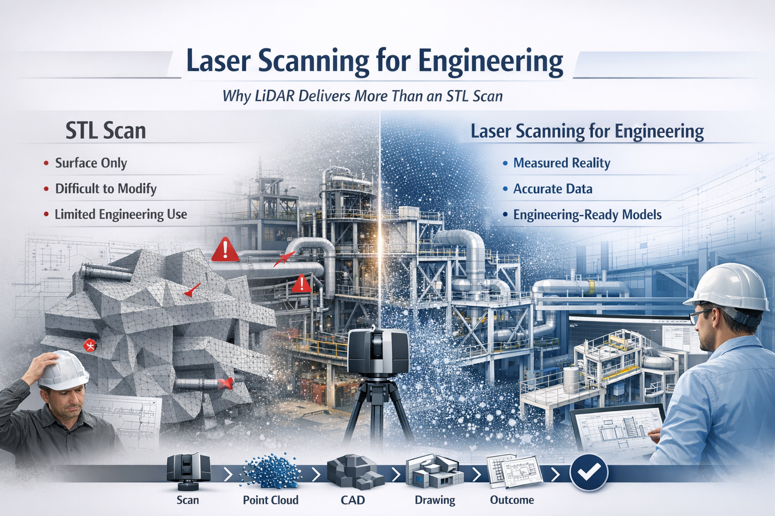
Laser scanning for engineering infographic comparing LiDAR point cloud data with STL mesh scanning, showing improved CAD modelling and engineering workflows.

Why LiDAR Delivers Real Engineering Outcomes

In modern engineering, accuracy is everything. Whether you are working in mining, manufacturing, infrastructure, or plant design, the difference between success and costly rework often comes down to how well you understand what has actually been built.

This is where laser scanning for engineering has become a critical tool.

While many providers offer โ€œ3D scanning,โ€ not all data is created equal. There is a significant difference between engineering-grade LiDAR point cloud data and basic STL mesh outputs. Understanding that difference can determine whether your project moves forward efficientlyโ€”or gets stuck in rework, assumptions, and redesign.


3D LiDAR scanning and 3D modelling service button โ€” laser scanner capturing a point cloud for engineering and CAD modelling
Mechanical engineering services

What is Laser Scanning for Engineering?

Laser scanning for engineering uses LiDAR (Light Detection and Ranging) technology to capture millions of precise measurements of a physical environment. The result is a high-density point cloudโ€”a true digital representation of reality.

Unlike traditional measurement methods, LiDAR captures:

  • Complex geometry
  • Structural relationships
  • Equipment positioning
  • Real-world deviations from design

This data becomes the foundation for:

  • CAD modelling (SolidWorks, AutoCAD, Revit)
  • Engineering drawings
  • Clash detection
  • Retrofit and upgrade design

In short, it bridges the gap between design intent and as-built reality.


The Problem with STL-Based Scanning

Many scanning providers deliver outputs as STL, OBJ, or mesh files. While these formats are useful for visualisation or 3D printing, they fall short in engineering applications.

Key limitations of STL scans:

  • No intelligence โ€“ Meshes are just surfaces, not structured geometry
  • Difficult to modify โ€“ Not suitable for parametric design workflows
  • Poor for engineering drawings โ€“ Cannot easily generate sections, tolerances, or fabrication details
  • Heavy and inefficient โ€“ Large file sizes with limited usability
  • No clear chain of accuracy โ€“ Hard to verify measurement reliability

In practical terms, an STL file often becomes a dead-end deliverableโ€”you can look at it, but you canโ€™t engineer from it effectively.


Why LiDAR Point Clouds Are Built for Engineering

LiDAR-based laser scanning for engineering produces structured, measurable, and verifiable data that integrates directly into engineering workflows.

Key advantages:

1. True-to-Reality Accuracy

Point clouds capture millions of measured points, providing a high-confidence representation of the real world.

2. Direct CAD Integration

Data can be converted into:

  • Parametric 3D models
  • Fabrication-ready drawings
  • Plant layouts and assemblies

3. Supports Engineering Decisions

Engineers can:

  • Measure directly from the dataset
  • Validate clearances and tolerances
  • Design with confidence

4. Enables Retrofit and Brownfield Design

In existing plants, nothing is ever exactly โ€œas drawn.โ€ LiDAR ensures your design fits what is actually there, not what was intended years ago.

5. Reduces Risk and Rework

Accurate input data leads to:

  • Fewer site revisits
  • Reduced fabrication errors
  • Lower project costs

6. Maintains Chain of Custody

Engineering-grade scanning supports data governance, traceability, and verificationโ€”critical in legal, compliance, and high-risk environments.


Engineering vs Visualisation: A Critical Distinction

A key misunderstanding in the industry is assuming all 3D scanning is equal.

  • STL / Mesh Scanning โ†’ Visualisation Output
  • LiDAR Point Cloud โ†’ Engineering Input

If your goal is:

  • 3D printing โ†’ STL may be enough
  • Engineering design, fabrication, or upgrades โ†’ LiDAR is essential

Real-World Application: Engineering in Practice

Across mining, manufacturing, and infrastructure, laser scanning for engineering is used to:

  • Capture conveyor systems before modification
  • Model structural steel for upgrades
  • Verify equipment installation
  • Design pipework and mechanical systems
  • Plan shutdown works with precision

Instead of guessing dimensions or relying on outdated drawings, engineers work from measured reality.


The Workflow That Delivers Results

A proper engineering workflow looks like this:

Scan โ†’ Register โ†’ Model โ†’ Detail โ†’ Deliver

Not:

Scan โ†’ Export STL โ†’ End

That difference defines whether you receive a usable engineering deliverable or just a digital artifact.


3D CAD Modelling Australia service banner for Hamilton By Design

Laser scanning for engineering is not just about capturing dataโ€”itโ€™s about enabling better engineering outcomes.

LiDAR-based point cloud data provides:

  • Accuracy
  • Usability
  • Engineering value

In contrast, STL-based scanning often limits what you can achieve.

If your project requires real design, real drawings, and real decisions, then the choice is clear:

Use laser scanning for engineeringโ€”not just scanning for appearance.

Our clients

Contact Us

Name
Would you like us to arrange a phone consultation for you?
Address
3D CAD Modelling Australia service banner for Hamilton By Design
Australian Drafting logo featuring bold white text reading "Australian Drafting" centred on a blue rounded rectangle background.
Engineering Governance title graphic featuring bold white text reading "Engineering Governance" centred on a blue rounded rectangle background.
Mechanical, Structural & Pipework Drafting service banner by Hamilton By Design featuring white text on a blue background.
Mechanical engineering services
Blue rounded button with the text โ€œSolidWorks Designโ€ in white.
Finite Element Analysis (FEA) engineering simulation button
3D LiDAR Scanning Darwin for engineering surveys, laser scanning, reality capture and point cloud modelling services
3D LiDAR Scanning Australia engineering services for laser scanning, reality capture, scan-to-CAD, Scan-to-BIM and as-built documentation across Australia
3D LiDAR scanning services on the Central Coast providing engineering-grade laser scanning, point cloud capture, scan-to-CAD modelling and industrial reality capture for infrastructure and industrial projects.
3D LiDAR Scanning Perth for engineering surveys, laser scanning, reality capture and point cloud modelling services
3D LiDAR Scanning Sydney for engineering surveys, laser scanning, reality capture and point cloud modelling services
3D LiDAR Scanning Brisbane for engineering surveys, laser scanning, reality capture and point cloud modelling services
3D LiDAR Scanning Canberra for engineering surveys, laser scanning, reality capture and point cloud modelling services
3D LiDAR Scanning Newcastle for engineering surveys, laser scanning, reality capture and point cloud modelling services
3D LiDAR Scanning Adelaide for engineering surveys, laser scanning, reality capture and point cloud modelling services

High Court Changes Engineering Liability

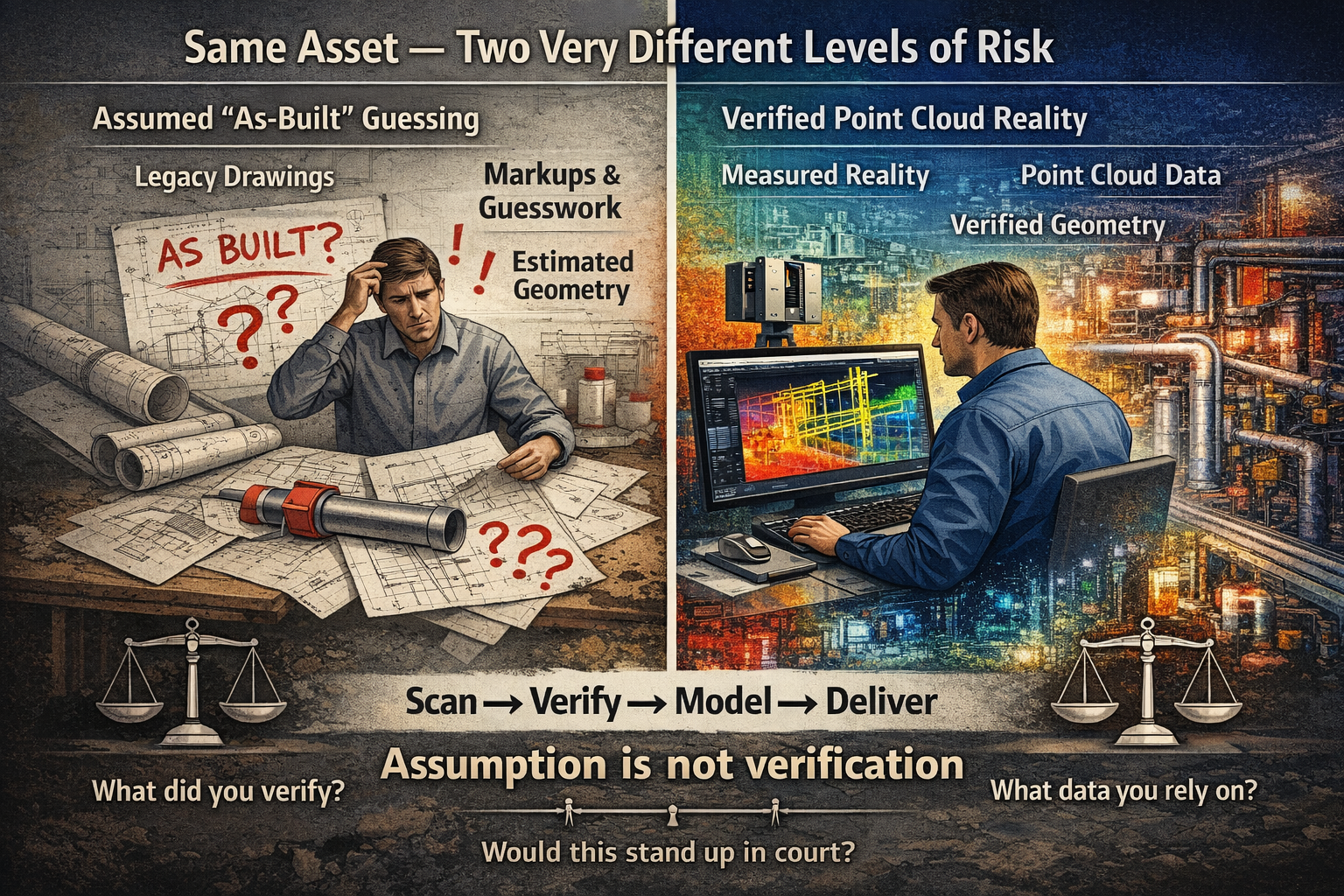
Split-screen engineering graphic comparing assumed as-built drawings with verified point cloud scanning data, highlighting the difference between estimated geometry and measured reality.

The High Court Just Changed Engineering Liability โ€” Why โ€œAs-Built Guessingโ€ Is No Longer Enough

The recent High Court decision in Pafburn Pty Ltd v The Owners โ€“ Strata Plan No 84674 has been widely discussed across the construction and legal sectors. Most commentary has focused on developers and builders, particularly the finding that they can be held fully liable for defects and cannot rely on proportionate liability to distribute responsibility.

But for engineers, designers, and anyone working in brownfield environments, the real impact runs deeper.

This case signals a clear shift in expectation โ€” away from assumption, and toward verified reality.


3D LiDAR scanning and 3D modelling service button โ€” laser scanner capturing a point cloud for engineering and CAD modelling
Mechanical engineering services

The Hidden Risk in โ€œAs-Builtโ€ Drawings

Across many projects, particularly in retrofit, maintenance, and upgrade work, design offices rely on what are commonly referred to as โ€œas-builtโ€ drawings.

In theory, these drawings represent what has actually been constructed on site.

In practice, however, that is not always the case.

Many โ€œas-builtsโ€ are produced through:

  • Manual markups during construction
  • Redline drawings updated after installation
  • Verbal confirmation from site teams
  • Interpretation of incomplete or outdated information

In some cases, they are never formally verified at all.

This creates a fundamental problem.

The design office is making decisions based on information that may be:

  • Incomplete
  • Inaccurate
  • Or in the worst case โ€” assumed

The Question That Is Now Being Asked

Following this High Court decision, the legal environment is changing.

It is no longer sufficient to say:

โ€œI worked from the drawings provided.โ€

Instead, the question is becoming:

What should a competent engineer have verified?

This is a significant shift.

It places responsibility not just on what information was used โ€” but on whether that information should have been trusted in the first place.


Assumption vs Measured Reality

At its core, this issue comes down to a simple comparison:

Does guessing what has been built offer the same level of coverage as measured data?

The answer is increasingly clear โ€” it does not.

When geometry is assumed:

  • Tolerances are unknown
  • Deviations from design are hidden
  • Errors compound as projects progress
  • Rework risk increases

More importantly, from a legal standpoint:

There is no defensible evidence of what actually existed at the time decisions were made.


The Role of Point Cloud Scanning

This is where point cloud scanning and reality capture fundamentally change the workflow.

Rather than relying on interpretation, point cloud data provides a direct measurement of site conditions.

A properly captured scan:

  • Records millions of measured points across the asset
  • Captures geometry exactly as installed
  • Provides a timestamped dataset of site conditions
  • Can be referenced, rechecked, and validated at any time

Most importantly, it creates a feedback loop between site and design.

Instead of guessing what has been built, the design office receives:

  • Accurate geometry
  • Verified spatial relationships
  • Real-world constraints

This allows models and drawings to be developed based on reality, not assumption.


Feeding Reality Back Into the Design Office

One of the most overlooked issues in engineering workflows is the disconnect between site and design.

Information typically flows in one direction:

  • Design โ†’ Construction

But the return flow:

  • Construction โ†’ Design

Is often inconsistent or incomplete.

Point cloud scanning closes this gap.

By scanning installed conditions and feeding that data back into the design environment, engineers can:

  • Align models with actual site geometry
  • Identify clashes before fabrication or installation
  • Validate clearances and fitment
  • Reduce the risk of downstream errors

This is not just about accuracy โ€” it is about confidence.


Why This Matters More After the High Court Decision

The implications of Pafburn Pty Ltd v The Owners โ€“ Strata Plan No 84674 go beyond contractual structures.

They influence how engineering decisions are evaluated.

When something goes wrong, the question is no longer simply:

โ€œWho was responsible for the design?โ€

It becomes:

  • What information was relied upon?
  • Was it reasonable to rely on that information?
  • Could the actual conditions have been verified?

If the tools to verify existed โ€” and were not used โ€” that becomes part of the discussion.


From Design Intent to Verified Condition

The industry is moving through a transition.

Historically, projects were driven by:

  • Design intent
  • Nominal dimensions
  • Idealised geometry

Today, the expectation is shifting toward:

  • Verified condition
  • Measured data
  • Real-world constraints

This shift is particularly important in:

  • Brownfield upgrades
  • Industrial plants
  • Mining infrastructure
  • Retrofit and modification projects

Where existing conditions rarely match original design documentation.


Practical Implications for Engineers

For engineers and designers, this means a change in approach.

Relying solely on drawings โ€” particularly for existing assets โ€” introduces risk.

A more robust workflow includes:

  • Verification of critical geometry
  • Clear documentation of data sources
  • Separation of assumed vs measured information
  • Use of reality capture where accuracy matters

This is not about replacing engineering judgement.

It is about supporting that judgement with evidence.


Conclusion: Coverage, Confidence, and Accountability

At the centre of this discussion is a simple idea:

Not all information offers the same level of coverage.

โ€œAs-builtโ€ drawings based on interpretation provide one level of confidence.

Measured point cloud data provides another.

As legal expectations evolve, the difference between the two becomes more significant.

Guessing what has been built โ€” even when done carefully โ€” does not offer the same level of coverage as data that can be measured, verified, and defended.


How We Approach It

At Hamilton By Design, our workflow is built around this principle:

Scan โ†’ Verify โ†’ Model โ†’ Deliver

By capturing real-world conditions and feeding that data back into the design process, we reduce uncertainty and provide a clear basis for engineering decisions.

Not just for better outcomes โ€” but for greater accountability.


If your next project relies on โ€œas-builtโ€ drawings alone, it is worth asking:

Are they measuredโ€ฆ or assumed?

3D CAD Modelling Australia service banner for Hamilton By Design

Our clients