Engineering Design and Drafting Services | Hamilton By Design

Engineering design and drafting for an industrial plant, showing 3D CAD modelling, technical drawings, LiDAR scanning and fabrication documentation.

Engineering Design and Drafting for Industrial, Mining and Infrastructure Projects

Successful engineering projects depend on more than a good idea. They require accurate information, practical design decisions and clear technical documentation that can be understood by engineers, fabricators, contractors, installers and asset owners.

Engineering design and drafting connect the initial project requirement with the final manufactured or installed result. They transform site information, calculations, concepts and operational requirements into coordinated 3D models and technical drawings.

Hamilton By Design provides Australian engineering design and drafting services for industrial plants, mining operations, manufacturing facilities, infrastructure projects and brownfield upgrades.

The objective is not simply to produce drawings. It is to create practical engineering information that supports decision-making, procurement, fabrication, construction, installation, operation and future maintenance.

What Is Engineering Design and Drafting?

Engineering design is the process of developing a practical solution to a technical problem. It considers how an asset should function, how it will be manufactured or constructed, how it interfaces with existing equipment and how it can be safely operated and maintained.

Engineering drafting communicates that solution through accurate models and drawings.

Depending on the project, engineering drafting deliverables may include:

  • three-dimensional CAD models
  • general arrangement drawings
  • manufacturing drawings
  • structural steel layouts
  • fabrication and workshop drawings
  • assembly and exploded views
  • pipework layouts and isometrics
  • equipment arrangement drawings
  • installation details
  • bills of materials
  • sections, elevations and details
  • as-built documentation
  • redline drawing updates

The design and drafting stages should work together. A technically sound concept must be converted into documentation that is clear, coordinated and suitable for its intended use.

Hamilton By Designโ€™s broader mechanical engineering services connect engineering analysis, site investigation, CAD modelling and drafting within a coordinated project workflow.

Why Engineering-Led Drafting Matters

Drafting software can create accurate lines and geometry, but software alone does not determine whether a design is practical.

Engineering-led drafting considers the real conditions that affect fabrication and installation, including:

  • available materials and standard sections
  • welding and machining requirements
  • practical tolerances
  • equipment loads
  • access for assembly and maintenance
  • lifting and installation constraints
  • clearances around existing plant
  • interfaces with structural, mechanical and civil systems
  • relevant Australian Standards
  • the sequence in which components will be manufactured and installed

A drawing may appear complete while still containing unresolved engineering issues. For example, a platform may fit within the available space but restrict maintenance access. A pipe route may avoid one structural member while conflicting with another service. A fabricated frame may be dimensionally correct but impossible to lift into position as a complete assembly.

Combining engineering knowledge with professional mechanical and structural drafting helps identify these issues before they reach the workshop or site.

Mechanical Design and Drafting

Mechanical design and drafting are used to develop machinery, plant equipment and supporting systems.

Typical applications include:

  • conveyors and transfer stations
  • chutes and hoppers
  • mechanical guards
  • pump and motor arrangements
  • tanks and process equipment
  • equipment support frames
  • pipework and ducting
  • lifting and handling equipment
  • maintenance platforms
  • replacement components
  • machine modifications
  • industrial equipment layouts

The process may begin with an existing concept, a site problem, a marked-up drawing, a physical component or a functional requirement.

A mechanical design can then be developed progressively through concept layouts, review models, detailed assemblies and fabrication drawings. This incremental approach allows assumptions to be checked and important interfaces to be confirmed before unnecessary detailing is completed.

Structural and Fabrication Drafting

Industrial projects frequently require new structural steel to support equipment, improve access or accommodate plant modifications.

Structural and fabrication drafting may include:

  • platforms and walkways
  • stairs, ladders and handrails
  • equipment support structures
  • conveyor support frames
  • maintenance access systems
  • structural modifications
  • connection details
  • base plates and brackets
  • lifting frames
  • workshop drawing packages

Fabrication drawings need to communicate more than overall dimensions. They may also need to identify materials, weld requirements, hole positions, fasteners, surface treatments, part numbers and assembly relationships.

Clear documentation reduces uncertainty in the workshop and allows questions to be addressed before fabrication begins.

Using 3D Laser Scanning to Improve Design Accuracy

Brownfield and retrofit projects often begin with incomplete or outdated information.

Original drawings may no longer represent the installed plant. Equipment may have been moved, structural steel modified, pipework rerouted or access systems added over many years.

Manual measurements can capture selected dimensions, but they may not provide enough information to understand a congested three-dimensional environment.

Engineering-grade 3D laser scanning captures millions of measured points across visible plant, equipment and structures. These points form a registered point cloud representing existing site conditions.

The point cloud can support:

  • existing-condition verification
  • equipment positioning
  • clash detection
  • access and clearance reviews
  • pipework routing
  • structural modification planning
  • installation sequencing
  • fabrication interface checks
  • as-built documentation
  • reverse engineering

Scanning is particularly valuable where site access is limited, shutdown periods are short or fabrication errors would be costly.

From Point Cloud to Engineering Model

A point cloud is a detailed spatial record, but it is not automatically an engineering model.

The dataset must be reviewed in relation to the project objective. Critical equipment, structures and interfaces can then be converted into practical CAD geometry.

Hamilton By Design provides point-cloud-to-AutoCAD services for projects requiring 2D plans, sections, elevations, layouts and engineering drawings developed from scanned site conditions.

Depending on the project, point-cloud information may be used to produce:

  • simplified equipment envelopes
  • structural steel models
  • mechanical assemblies
  • plant layouts
  • installation interfaces
  • existing pipework routes
  • general arrangement drawings
  • proposed-design overlays
  • fabrication geometry

Not every visible object needs to be modelled. The appropriate level of detail depends on how the information will be used.

Modelling only the important project interfaces can reduce processing time while preserving the information needed for engineering decisions.

SolidWorks Design and Drafting

Three-dimensional parametric modelling allows equipment, parts and assemblies to be developed in a coordinated digital environment.

Hamilton By Design uses SolidWorks for engineering and drafting to produce parts, assemblies, layouts, manufacturing drawings and design documentation.

A coordinated SolidWorks model can assist with:

  • visualising the proposed design
  • checking component relationships
  • identifying potential clashes
  • creating drawing views and sections
  • generating bills of materials
  • managing design revisions
  • developing sheet-metal components
  • producing assembly documentation
  • exporting neutral CAD formats for other project participants

Three-dimensional models also allow clients, fabricators and site teams to review a proposal before fabrication begins. This can make design discussions clearer than relying only on conventional two-dimensional drawings.

Engineering Design for Brownfield Projects

Brownfield projects involve modifying or adding to an existing facility.

They can be more complex than greenfield projects because the new design must fit around installed structures, operating equipment and established services.

Typical brownfield constraints include:

  • restricted installation space
  • unknown or undocumented geometry
  • limited site access
  • existing assets that must remain operational
  • short shutdown windows
  • multiple design interfaces
  • legacy equipment and drawings
  • restricted lifting and transport routes

A practical brownfield workflow may involve site inspection, laser scanning, point-cloud registration, CAD modelling, engineering review and staged drawing development.

The design team can first confirm the existing conditions and major interfaces. The proposed design can then be developed around reliable site data rather than assumptions.

Supporting Fabrication and Installation

Engineering design and drafting should make the next stage of the project easier.

Fabricators need clear information about what must be manufactured. Installers need to understand where components are located and how they connect to the existing plant. Project managers need confidence that interfaces have been reviewed.

Useful drawing packages may include:

  • drawing registers
  • general arrangement drawings
  • detailed part drawings
  • welded assembly drawings
  • installation layouts
  • material specifications
  • bills of materials
  • revision records
  • notes identifying site verification requirements

Where dimensions cannot be confirmed, assumptions and hold points should be clearly identified rather than hidden within the model.

This provides a more transparent basis for project decisions and helps prevent unverified information from being treated as confirmed site data.

Local and Australia-Wide Drafting Support

Hamilton By Design is based on the NSW Central Coast and supports projects throughout Australia.

Clients requiring local assistance can learn more about engineering drafting services on the Central Coast, including mechanical drafting, fabrication drawings, legacy drawing updates and as-built documentation.

Services can be provided for individual components, plant modifications, ongoing project support or larger engineering packages.

Frequently Asked Questions

What information is needed to begin an engineering drafting project?

Useful starting information may include sketches, photographs, existing drawings, dimensions, equipment data, design calculations, site constraints and the intended use of the final drawings. Where reliable site information is unavailable, a site inspection or 3D laser scan may be recommended.

Can drawings be produced from an existing physical component?

Yes. Existing components can be measured manually or captured using 3D scanning, depending on their size, complexity and required accuracy. The information can then be used to develop a reverse-engineered CAD model and manufacturing drawings.

What is the difference between a 3D model and a fabrication drawing?

A 3D model represents the geometry and relationships between components. A fabrication drawing communicates the dimensions, materials, tolerances, welds, finishes and other information required to manufacture the component. A model alone may not contain everything a fabricator needs.

Can old drawings be updated?

Yes. Legacy paper drawings, PDFs, marked-up prints and older CAD files can be reviewed and converted into updated digital drawings. Site verification may be required where the existing asset has been modified since the original drawings were issued.

Can point clouds be used directly for design?

Yes. Point clouds can be referenced in CAD software to measure existing conditions, position proposed equipment and check clearances. Selected geometry can also be converted into structured CAD models where required.

Do all objects in a scan need to be modelled?

No. The modelling scope should reflect the engineering objective. Modelling only the relevant equipment, structures and interfaces is often more efficient than creating a highly detailed model of the entire facility.

What drawing formats can be supplied?

Typical deliverables may include PDF, DWG and DXF drawings, together with SolidWorks, STEP, SAT or Parasolid models. Point-cloud formats may include E57, RCP, RCS and LAS, depending on the project requirements.

Can Hamilton By Design support both design and site capture?

Yes. Hamilton By Design combines site measurement, 3D LiDAR scanning, engineering design, CAD modelling and drafting. This creates a coordinated workflow from existing-condition capture through to engineering documentation.

Additional answers about scanning, modelling and engineering deliverables are available in the Hamilton By Design frequently asked questions.

Discuss Your Engineering Design and Drafting Project

Accurate engineering design and drafting create a reliable connection between an initial requirement and the final fabricated or installed asset.

By combining practical engineering experience, 3D CAD modelling, LiDAR scanning and clear technical documentation, Hamilton By Design helps clients reduce uncertainty, coordinate project interfaces and develop information that can be used confidently by fabricators, contractors and site teams.

Whether the requirement involves a single replacement component, a mechanical assembly, structural steel, a plant upgrade or a complete brownfield documentation package, the process should begin by defining the project objective, critical interfaces and required deliverables.

Hamilton By Design Co.
Mechanical Engineering | 3D Laser Scanning | 3D Modelling
Australia-wide engineering and project support


Hamilton By Design logo displayed on a blue tilted rectangle with a grey gradient background

Contact Us – Talk To Us

Name
Would you like us to arrange a phone consultation for you?
Address

Our clients:



Engineering Resources for Mining, Mechanical and Industrial Design

Mining and industrial engineering design montage showing conveyors, pipework systems, structural steel platforms and a mechanical assembly CAD model.

Supporting Engineering Knowledge Across Multiple Industry Blogs

At Hamilton By Design Co., we regularly publish engineering insights, technical discussions, and project examples across a number of specialist industry blogs.

These resources support engineers, plant operators, maintenance managers, and project teams working across mining, manufacturing, industrial infrastructure and structural design.

Many of these posts explore the practical engineering challenges encountered when designing, upgrading, or reverse engineering industrial equipment and facilities.

Topics include:

  • Mining plant design
  • Conveyor transfer systems
  • Structural steel detailing
  • Mechanical drafting
  • SolidWorks engineering design
  • Point cloud modelling and laser scanning
  • Design for manufacturing
  • Industrial plant upgrades

These blogs form part of the broader Hamilton By Design engineering knowledge network, providing practical insight into the real-world challenges of industrial design and engineering projects.


Hamilton By Design Engineering Blog Network

Hamilton By Design Engineering Blog

https://hamiltonbydesign.blogspot.com

This blog focuses on engineering services delivered by Hamilton By Design, including:

  • 3D laser scanning for engineering projects
  • Reverse engineering workflows
  • Industrial plant modelling
  • Engineering design case studies

It provides insights into how scanning and modelling technologies are applied to real engineering projects across Australia.


Mining Infrastructure and SolidWorks Design

https://mininginfrastructuresolidworksdesign.blogspot.com

This engineering blog focuses on the design and modelling of mining infrastructure, including:

  • Conveyor systems
  • Transfer chutes
  • Structural supports
  • Plant layout modelling

Articles often explore how SolidWorks and engineering modelling tools are used to develop reliable infrastructure for mining and bulk material handling.


Chutes and Transfer Stations

https://chutesandtransferstations.blogspot.com

Transfer chutes are one of the most critical components in bulk material handling systems.

This blog discusses:

  • Common chute failures in mining plants
  • Conveyor loading problems
  • Transfer point design
  • Bulk material handling improvements

Engineering design decisions made at transfer stations can significantly impact conveyor reliability, maintenance costs, and plant performance.


Design for Manufacturing

https://design-for-manufacturing.blogspot.com

The Design for Manufacturing (DFM) blog focuses on improving product and equipment designs to simplify fabrication and assembly.

Topics include:

  • Fabrication-friendly engineering design
  • Cost reduction through smarter design
  • Manufacturing workflow improvements
  • Practical mechanical engineering tips

Industrial Design Australia

https://industrialdesignaustralia.blogspot.com

This blog discusses engineering and industrial design challenges across Australian industries including:

  • Mining infrastructure
  • Industrial plants
  • Equipment upgrades
  • Plant shutdown planning

It highlights the engineering considerations required when working within complex operating facilities.


Mechanical Drafting Sydney

https://mechanical-drafting-sydney.blogspot.com

This blog focuses on professional drafting services including:

  • Mechanical design documentation
  • Engineering drawings
  • Industrial layout modelling
  • Detailed fabrication drawings

It provides insights into the role of drafting in delivering successful engineering projects.


Pipework Detailing

https://pipeworkdetailing.blogspot.com

Industrial pipe systems are critical infrastructure within processing plants.

This blog covers:

  • Pipe routing design
  • Pipe spool drawings
  • Scan-to-model workflows
  • Pipework engineering documentation

The content is particularly relevant to projects where laser scanning is used to capture existing plant geometry before upgrades.


SolidWorks Designer

https://solidworksdesigner.blogspot.com

This blog focuses on 3D mechanical design using SolidWorks, including:

  • Industrial equipment design
  • Mechanical assemblies
  • Engineering modelling workflows
  • Reverse engineering projects

SolidWorks Sydney

https://solidworkssydney.blogspot.com

This site focuses on SolidWorks engineering services in Australia, including:

  • Mechanical design
  • Industrial equipment modelling
  • Manufacturing design support

Structural Detailing

https://structural-detailing.blogspot.com

Structural detailing plays an important role in industrial plant upgrades and infrastructure projects.

This blog discusses:

  • Structural steel detailing
  • Engineering drawings for fabrication
  • Industrial infrastructure design

Structural Drafting

https://structural-drafting.blogspot.com

This blog focuses on structural drafting services including:

  • Steel framing drawings
  • Fabrication documentation
  • Structural engineering support for industrial facilities.

Structural Steel Drafting

https://structural-steel-drafting.blogspot.com

This blog focuses specifically on steel structures used in industrial plants and mining facilities, including:

  • Conveyor structures
  • Plant platforms
  • Maintenance walkways
  • Equipment support frames

Supporting Industrial Engineering Projects Across Australia

These blogs collectively explore the practical engineering knowledge required to support industrial facilities across Australia.

Many of the engineering topics discussed across these blogs are connected to services provided by Hamilton By Design, including:

  • Engineering grade 3D laser scanning
  • Point cloud to engineering model workflows
  • Mechanical and structural engineering design
  • Reverse engineering of industrial equipment
  • Plant upgrades and shutdown preparation

These resources help engineers and plant operators better understand how modern digital engineering tools can support safer, more efficient industrial infrastructure projects.

Hamilton By Design logo displayed on a blue tilted rectangle with a grey gradient background

3D LiDAR scanning and 3D modelling service button โ€” laser scanner capturing a point cloud for engineering and CAD modelling
Mechanical engineering services
Name
Would you like us to arrange a phone consultation for you?
Address


3D CAD Modelling Australia service banner for Hamilton By Design

Mechanical Engineering | Structural Engineering


3D LiDAR Scanning Darwin for engineering surveys, laser scanning, reality capture and point cloud modelling services
3D LiDAR Scanning Australia engineering services for laser scanning, reality capture, scan-to-CAD, Scan-to-BIM and as-built documentation across Australia
3D LiDAR scanning services on the Central Coast providing engineering-grade laser scanning, point cloud capture, scan-to-CAD modelling and industrial reality capture for infrastructure and industrial projects.
3D LiDAR Scanning Perth for engineering surveys, laser scanning, reality capture and point cloud modelling services
3D LiDAR Scanning Sydney for engineering surveys, laser scanning, reality capture and point cloud modelling services
3D LiDAR Scanning Brisbane for engineering surveys, laser scanning, reality capture and point cloud modelling services
3D LiDAR Scanning Canberra for engineering surveys, laser scanning, reality capture and point cloud modelling services
3D LiDAR Scanning Newcastle for engineering surveys, laser scanning, reality capture and point cloud modelling services
3D LiDAR Scanning Adelaide for engineering surveys, laser scanning, reality capture and point cloud modelling services

Identifying Fastener Threads in the Field

Metric vs American vs British Threads โ€” and the Australian Standards That Govern Them

In maintenance workshops and brownfield sites, one of the most common hidden problems is not bolt strength โ€” it is thread identification.

Equipment imported from the USA, Europe and the UK often ends up assembled together on Australian sites.
The bolts may look identical.
They may even screw together.

But they are not interchangeable.

Incorrect thread matching damages load capacity, prevents correct preload, and leads to loosening, fatigue cracking and eventual failure.

This guide explains the major fastening thread systems encountered in Australia (excluding pipe threads), how to recognise them, and the Australian Standards that apply.


1. The Three Fastener Thread Systems

There are three main fastening thread families encountered in mechanical and structural equipment:

SystemOriginThread AngleTypical Location
Metric ISOAustralia / Europe / modern equipment60ยฐMost modern machinery
Unified (UNC/UNF)USA60ยฐMining & imported plant
Whitworth (BSW/BSF/BA)UK / older Commonwealth55ยฐOlder equipment & legacy machinery

Even though UNC and Metric share a 60ยฐ angle, the pitch is different โ€” therefore they are not compatible.

Whitworth threads are particularly problematic because they will partially screw into metric or UNC holes before binding.


2. Metric Threads (ISO Metric โ€” Australian Standard Fasteners)

These are the primary fastening threads used in Australia.

(Coarse pitch series)

SizeMajor DiameterPitchMinor Diameter (approx)
M66.0 mm1.04.8 mm
M88.0 mm1.256.5 mm
M1010.0 mm1.58.2 mm
M1212.0 mm1.759.9 mm
M1616.0 mm2.013.8 mm
M2020.0 mm2.517.3 mm
M2424.0 mm3.020.8 mm

Fine pitch versions also exist for vibration and adjustment applications.

Typical Uses

  • Structural steel connections
  • Machinery assembly
  • Guards and access platforms
  • General engineering

3. Unified American Threads (UNC / UNF)

Common on imported mining and mobile equipment.

UNC โ€“ Coarse

SizeMajor DiameterPitch
1/4-206.35 mm1.27 mm
3/8-169.53 mm1.59 mm
1/2-1312.70 mm1.95 mm
3/4-1019.05 mm2.54 mm
1-825.40 mm3.18 mm

UNF โ€“ Fine

Used where vibration resistance is required.

Key Characteristic
UNC bolts will often start threading into metric holes but will not achieve correct preload.


4. British Threads (Whitworth Form)

Recognised by their 55ยฐ thread angle.

BSW โ€“ Coarse

SizeMajor DiameterPitch
1/4 BSW6.35 mm1.34 mm
3/8 BSW9.53 mm1.59 mm
1/2 BSW12.70 mm2.12 mm
3/4 BSW19.05 mm2.54 mm

BSF โ€“ Fine

Used historically in machinery.

BA Threads

Small instrumentation and electrical fasteners.

Typical Location

  • Pre-1980 plant
  • UK imported machinery
  • Electrical equipment

Why Incorrect Thread Matching Causes Failures

Threads do not primarily carry shear load โ€” they generate preload.

If pitch or angle differs:

  • preload is reduced
  • flank contact is uneven
  • joint loosens under vibration
  • fatigue cracking begins

Many failures blamed on vibration are actually incorrect thread engagement.


Field Identification Tips

ObservationLikely Thread
Marked M12Metric
Fraction size (1/2, 3/4)UNC/UNF or Whitworth
Smooth but tight engagementWrong pitch
Binds after 2 turnsWhitworth vs Metric

Thread gauge confirmation is always recommended.


Australian Standards Relating to Fastener Threads

Metric Thread Geometry

AS 1721 โ€” General purpose metric screw threads
AS 1275 โ€” Metric screw threads for fasteners

Fastener Product Standards

AS 1110 โ€” Metric hex bolts and screws
AS 1111 โ€” Commercial hex bolts and screws
AS 1112 โ€” Hexagon nuts
AS 1420 โ€” Socket head cap screws

Mechanical Properties

AS/NZS 4291.1 โ€” Mechanical properties of bolts, screws and studs
AS/NZS 4291.2 โ€” Mechanical properties of nuts
ISO 898-1 / ISO 898-2 โ€” Adopted strength properties
ISO 3506 โ€” Stainless steel fasteners

Structural Bolting

AS/NZS 1252 โ€” High strength structural bolting assemblies
AS 4100 โ€” Steel structures design
AS/NZS 5131 โ€” Fabrication and erection of structural steel

Coatings and Fit Allowances

AS/NZS 1214 โ€” Galvanised coatings on threaded fasteners
AS/NZS 4680 โ€” Hot dip galvanising
AS 2312.2 โ€” Corrosion protection guide
AS 1897 โ€” Electroplated coatings

3D LiDAR scanning and 3D modelling service button โ€” laser scanner capturing a point cloud for engineering and CAD modelling
Mechanical engineering services
Name
Would you like us to arrange a phone consultation for you?
Address

3D CAD Modelling Australia service banner for Hamilton By Design
3D LiDAR scanning and 3D modelling service button โ€” laser scanner capturing a point cloud for engineering and CAD modelling
Mechanical engineering services
Mechanical drafting services button
Blue rounded button with the text โ€œSolidWorks Designโ€ in white.
Blue banner graphic displaying the text "Point Cloud to CAD - Australia" in large white lettering, representing point cloud processing, scan-to-CAD conversion and digital engineering services across Australia.
Mechanical, Structural & Pipework Drafting service banner by Hamilton By Design featuring white text on a blue background.
Engineering Governance title graphic featuring bold white text reading "Engineering Governance" centred on a blue rounded rectangle background.
Mining Plant Upgrades promotional graphic with bold white text on a blue background representing mining infrastructure, plant improvement, and engineering upgrade projects.
3D Pipework promotional graphic with bold white text on a blue background representing pipework design, modelling, drafting, and engineering services.
Australian Drafting logo featuring bold white text reading "Australian Drafting" centred on a blue rounded rectangle background.
3D Pipework promotional graphic with bold white text on a blue background representing pipework design, modelling, drafting, and engineering services.
Mining Plant Upgrades promotional graphic with bold white text on a blue background representing mining infrastructure, plant improvement, and engineering upgrade projects.
3D LiDAR Scanning for Engineering Projects title graphic featuring bold white text on a blue rounded rectangle background.
Australian Drafting logo featuring bold white text reading "Australian Drafting" centred on a blue rounded rectangle background.
Engineering Governance title graphic featuring bold white text reading "Engineering Governance" centred on a blue rounded rectangle background.
Mechanical, Structural & Pipework Drafting service banner by Hamilton By Design featuring white text on a blue background.
Mechanical engineering services
Blue rounded button with the text โ€œSolidWorks Designโ€ in white.
Finite Element Analysis (FEA) engineering simulation button

Mechanical Engineering | Structural Engineering


Bolts, Grades, Materials and Standards

A Practical Engineering Guide to Correct Fastener Selection in Australia

Bolts are one of the most common engineered components on any project โ€” and also one of the most misunderstood.

In drawings they appear as a simple note:
M16 โ€“ 8.8 โ€“ GALV

Yet behind that small call-out sits structural capacity, fatigue life, corrosion resistance, inspection compliance, and legal responsibility.

Many engineering failures do not occur because a beam was undersized or a calculation was incorrect.
They occur because the wrong fastener type was selected for the application.

This article explains:

  • Bolt and nut property classes
  • Where each class should be used
  • Carbon steel vs stainless steel
  • Coatings and environment suitability
  • Structural vs mechanical bolting
  • Australian Standards governing fasteners
  • How to review and challenge incorrect selections โ€” especially when mentoring graduate engineers

1. The Three Different Worlds of Bolting

Most confusion exists because people think a bolt is simply a stronger or weaker version of the same item.

In reality, bolts exist in three different engineering systems:

SystemPurposeGoverning Standards
General Mechanical FasteningHolding components togetherISO / AS 1110 / AS 4291
Structural BoltingLoad transfer between steel membersAS/NZS 1252 / AS 4100
Corrosion Resistant FasteningSurvive environmentStainless / coatings standards

Using a bolt from the wrong system often creates hidden failures.


2. Bolt Property Classes (Metric)

Metric bolts are marked with numbers such as 4.6, 8.8, 10.9, 12.9

These numbers define material strength.

What the Numbers Mean

First number โ†’ Ultimate tensile strength (ร—100 MPa)
Second number โ†’ Yield ratio

Example:

8.8 bolt
800 MPa tensile strength
Yields at 80% = 640 MPa


Typical Bolt Classes and Their Uses

ClassStrength LevelTypical Applications
4.6LowLight brackets, sheet metal
4.8Lowโ€“mediumGeneral hardware
5.8MediumAutomotive covers
6.8MediumMachinery guards
8.8High tensileGeneral engineering & structural connections
9.8Higher tensileAutomotive mechanical
10.9Very high tensileMining equipment, heavy plant
12.9Ultra high tensileTooling, precision machinery

Important Engineering Concept

A stronger bolt is not always better.

Higher strength bolts:

  • are less ductile
  • tolerate less misalignment
  • fatigue faster in bending

Many failures occur when 12.9 bolts are used where 8.8 bolts were intended.


3. Nut Property Classes

Nuts are graded differently.
They must match the bolt strength.

Nut ClassSuitable Bolt
44.6
55.8
66.8
88.8
99.8
1010.9
1212.9

Critical Rule

Nut class must be equal or higher than bolt class first number

If not, the joint will strip before correct preload is reached.


4. Carbon Steel vs Stainless Steel

Many installations choose stainless assuming it is โ€œbetterโ€.

It is not stronger โ€” it is more corrosion resistant.


Mechanical Comparison

PropertyHigh Tensile Carbon SteelStainless Steel
StrengthHighMedium
Fatigue resistanceGoodLower
Vibration resistanceGoodPoorer
Corrosion resistanceDepends on coatingExcellent
Galling riskVery lowHigh
Torque capacityHighLimited

Stainless Grades

GradeEquivalent StrengthTypical Use
A2-50~5.8General hardware
A2-70~7.0Outdoor equipment
A4-80~8.8 tensileMarine / chemical

Important

Stainless steel often fails in structural joints due to:

  • lower yield strength
  • thread galling
  • relaxation under load

5. Coatings and Environment Suitability

Carbon steel requires corrosion protection.

CoatingEnvironment
Black oxideIndoor machinery
Zinc platedIndoor dry
Zinc passivateWorkshop conditions
Hot dip galvanisedOutdoor structural
Mechanical galvanisedStructural bolting
Dacromet / GeometMining & heavy corrosion

Engineering Impact of Coatings

Coatings change friction.

Friction changes preload.

Therefore torque charts must match coating type.

Incorrect torque values are one of the most common installation errors.


6. Structural Bolting vs Mechanical Bolting

These must never be confused.

Mechanical Bolting

Purpose: hold parts together

Failure mode: loosening

Structural Bolting

Purpose: transfer load through friction or bearing

Failure mode: structural collapse

Structural bolts require:

  • certified assemblies
  • controlled tightening method
  • inspection records

General hardware bolts must never be substituted.


7. Storage and Handling Requirements

Fasteners can degrade before use.

Problems Caused by Poor Storage

  • Coating breakdown
  • Hydrogen embrittlement risk
  • Rust under galvanising
  • Lost certification traceability
  • Incorrect torque performance

Recommended Storage Practices

Environment

Dry
Covered
Off concrete
Stable temperature

Handling

Keep manufacturer packaging
Do not mix batches
Record heat numbers

Stainless Steel

Must be isolated from carbon steel contamination.

Carbon particles embed โ†’ rust later appears


8. Australian Standards for Fasteners

Below is a consolidated list relevant to Australian engineering practice.


Mechanical Properties

AS/NZS 4291.1 โ€” Mechanical properties of bolts, screws and studs
AS/NZS 4291.2 โ€” Mechanical properties of nuts
ISO 898-1 / ISO 898-2 โ€” Referenced strength properties
ISO 3506 โ€” Stainless steel fasteners


Dimensions & Threads

AS 1110 โ€” Metric hex bolts & screws
AS 1111 โ€” Metric fasteners
AS 1112 โ€” Hexagon nuts
AS 1275 โ€” Metric screw threads
AS 1721 โ€” General purpose metric threads


Structural Bolting

AS/NZS 1252 โ€” High strength structural bolting assemblies
AS 4100 โ€” Steel structures design
AS/NZS 5131 โ€” Structural steel fabrication & erection


3D LiDAR scanning and 3D modelling service button โ€” laser scanner capturing a point cloud for engineering and CAD modelling
Mechanical engineering services

Corrosion Protection

AS/NZS 1214 โ€” Galvanised coatings on threaded fasteners
AS/NZS 4680 โ€” Hot dip galvanising
AS 2312.2 โ€” Corrosion protection guide
AS 1897 โ€” Electroplated coatings


Locking and Reliability

AS 4145.2 โ€” Locking devices for fasteners


9. Mentoring the Graduate Engineer

What To Do When the Selection Is Wrong

One of the responsibilities of senior engineers is not just checking work โ€” but teaching judgement.

A graduate will often select bolts by:

  • copying an old drawing
  • choosing stainless for safety
  • choosing highest strength available
  • assuming galvanised means structural

Rather than correcting immediately, guide the reasoning.


Questions That Help Them Learn

Instead of saying โ€œthat is wrongโ€, ask:

What load path is the bolt carrying?
Is it clamping, locating, or supporting?

What failure mode are we preventing?
Slip, fatigue, shear, corrosion, loosening?

Is the environment or the force governing selection?

Does the standard require a certified assembly?

What inspection method applies?


The Goal

Teach that engineering is not selecting a stronger component โ€”
it is selecting the correct component for the failure mode.


Hamilton By Design logo displayed on a blue tilted rectangle with a grey gradient background

Conclusion

Fasteners are engineered components.

Correct selection depends on understanding:

  • strength class
  • application type
  • environment
  • installation method
  • applicable standards

Most bolted joint failures occur not from calculation error, but from incorrect assumptions about what the bolt is meant to do.

Engineering quality is achieved when design intent matches real behaviour.

Name
Would you like us to arrange a phone consultation for you?
Address
3D CAD Modelling Australia service banner for Hamilton By Design
Finite Element Analysis (FEA) engineering simulation button
Mechanical engineering services

Why Good Design Matters More Than Project Management

Why Engineering Design Matters More Than Project Management

Lessons from Tailings Dam Failures in the Global Mining Industry

In engineering-led industries such as mining, construction, and heavy manufacturing, project management is often seen as the key to success โ€” on time, on budget, and on scope.

However, history shows that when failures occur, they are rarely caused by poor project management alone.

Some of the most serious industrial failures in the world โ€” including tailings dam collapses โ€” demonstrate a critical truth:

Project management cannot compensate for poor or marginal engineering design.

At Hamilton By Design, we believe design sets the safety ceiling. Project management operates within it.


Project Management Executes โ€” Design Determines Risk

Project management is essential. It coordinates people, schedules, procurement, and delivery. But it does not:

  • Increase a structureโ€™s factor of safety
  • Prevent liquefaction
  • Change material behaviour
  • Improve drainage capacity
  • Create resilience to abnormal conditions

Those outcomes are locked in at the design stage.

If a system requires perfect execution to remain safe, then the design is already fragile.

Good engineering design assumes:

  • Humans make mistakes
  • Weather exceeds forecasts
  • Equipment fails
  • Maintenance is imperfect

And it builds in margin, redundancy, and tolerance accordingly.


Tailings Dam Failures: A Clear Engineering Example

Tailings dam failures provide one of the clearest illustrations of the difference between design responsibility and project management responsibility.

Post-failure investigations across multiple countries consistently show that:

  • Many failed dams were operating as intended
  • Rainfall events were often within design assumptions
  • Operators followed approved procedures
  • Warning signs existed but reflected systemic weakness, not isolated mistakes

The common thread was not poor scheduling or cost control โ€” it was design philosophy.

Typical design-level issues identified:

  • Excess water retained in tailings
  • Low-density slurry disposal
  • Marginal stability under normal variability
  • Reliance on operational controls to maintain safety
  • Legacy designs never upgraded to match increased production

When a dam fails after a rainfall event, the rain is usually the trigger โ€” not the root cause.


Why Design Must Be Forgiving of Operations

Engineering design should be robust, not optimistic.

A safe design is one where:

  • Small operational deviations do not create instability
  • Water balance can tolerate extreme events
  • Safety does not depend on constant intervention
  • Failure modes are slow, visible, and recoverable

When operators or project managers are forced to โ€œmanage aroundโ€ design weaknesses, risk accumulates silently.

If safety relies on perfect behaviour, the system is unsafe by design.


The Australian Perspective: Design First, Then Manage

Australiaโ€™s generally strong tailings safety record reflects a broader engineering mindset:

  • Conservative design assumptions
  • Strong emphasis on water recovery and thickened tailings
  • Avoidance of high-risk construction methods
  • Independent engineering review
  • Design-for-closure thinking

Project management remains critical โ€” but it is not asked to compensate for marginal engineering.

This philosophy extends beyond tailings dams into:

  • Bulk materials handling
  • Structural steelwork
  • Brownfield upgrades
  • Shutdown-critical fabrication
  • Plant modifications

What This Means for Mining and Industrial Projects

The lesson is simple but powerful:

Engineering design controls risk.
Project management controls delivery.

When design is done properly:

  • Project management becomes easier
  • Variability is absorbed safely
  • Failures become unlikely rather than inevitable

When design is compromised:

  • Project management is left managing risk it cannot remove
  • The system becomes fragile
  • Incidents become a matter of when, not if

Our Approach at Hamilton By Design

At Hamilton By Design, we work from the principle that:

  • Design must be defensible
  • Assumptions must be explicit
  • Failure modes must be understood
  • Engineering judgement must lead delivery

Whether weโ€™re supporting:

  • Mining infrastructure
  • Tailings-adjacent plant systems
  • Bulk materials handling
  • Brownfield modifications
  • Shutdown-critical upgrades

We prioritise engineering-led design decisions that reduce reliance on operational heroics.


Final Thought

Project management is essential โ€” but it should never be asked to solve problems that only engineering design can prevent.

The safest projects are not the best managed ones โ€”
they are the best designed ones.

Hamilton By Design logo displayed on a blue tilted rectangle with a grey gradient background
3D LiDAR scanning and 3D modelling service button โ€” laser scanner capturing a point cloud for engineering and CAD modelling
Mechanical engineering services

Talk to an Engineer First

If your project involves:

  • High-risk infrastructure
  • Brownfield modifications
  • Water-sensitive systems
  • Shutdown-critical works

Get engineering involved early.
Contact Hamilton By Design to discuss an engineering-led approach that reduces risk before construction begins or Be part of the discussion.

Name
Would you like us to arrange a phone consultation for you?
Address
3D LiDAR scanning and 3D modelling service button โ€” laser scanner capturing a point cloud for engineering and CAD modelling
Mechanical engineering services
Finite Element Analysis (FEA) engineering simulation button
Mechanical engineering services

SolidWorks Perth | Engineering-Led SolidWorks Drafting Services

Engineering-led SolidWorks drafting in Perth with 25 years of Hamilton By Design experience

If youโ€™re searching for SolidWorks Perth, youโ€™re likely looking for reliable SolidWorks drafting support that produces drawings and models that fabricate and install correctly โ€” not just CAD files that look good on screen.

Hamilton By Design provides engineer-led SolidWorks drafting services in Perth, supporting WA fabricators, contractors, and industrial operators with fabrication-ready documentation and practical engineering judgement.


Engineer-Led SolidWorks Drafting Support for Perth & WA Projects

Perth projects often involve brownfield assets, tight access, and programmes where mistakes turn into rework, delays, and cost. The biggest risk isnโ€™t โ€œcan we model it?โ€ โ€” itโ€™s whether the drawings reflect:

  • Site reality
  • Fabrication constraints
  • Tolerances and interfaces
  • Installation sequencing and access

Thatโ€™s why our SolidWorks drafting is engineering-led.


Who Engages SolidWorks Drafting Services in Perth

Perth clients commonly engage us when they need to:

  • Outsource SolidWorks drafting with engineering oversight
  • Update or recreate drawings that no longer match existing plant
  • Add drafting capacity during tenders, shutdowns, or project spikes
  • Produce workshop drawings that fabricators can build from
  • Reduce fit-up risk on modifications and upgrades

Many enquiries start as โ€œhire a SolidWorks drafter Perthโ€ โ€” but our service is built for clients who also want engineering judgement behind every drawing.


SolidWorks Drafting Services We Provide in Perth

Our Perth SolidWorks drafting support includes:

  • Mechanical part and assembly drafting
  • Fabrication-ready workshop drawings
  • Structural and support steel detailing (where applicable)
  • Upgrade and modification drawing packages
  • Reverse-engineered part drawings (from site data)
  • As-built documentation and drawing updates
  • CAD outputs suitable for fabrication workflows and project handover

All deliverables are created with fabrication and installation readiness in mind โ€” not just CAD accuracy.


Why Engineering-Led Drafting Matters

SolidWorks is a powerful platform, but CAD alone does not prevent project failure.

Engineering-led drafting helps Perth teams by:

  • Reducing tolerance and interface clashes before fabrication
  • Producing drawings that are clear and buildable under real constraints
  • Supporting tender-stage decisions with accurate documentation
  • Minimising rework and improving shutdown certainty

This approach is particularly valuable on brownfield and shutdown-critical works in WA.


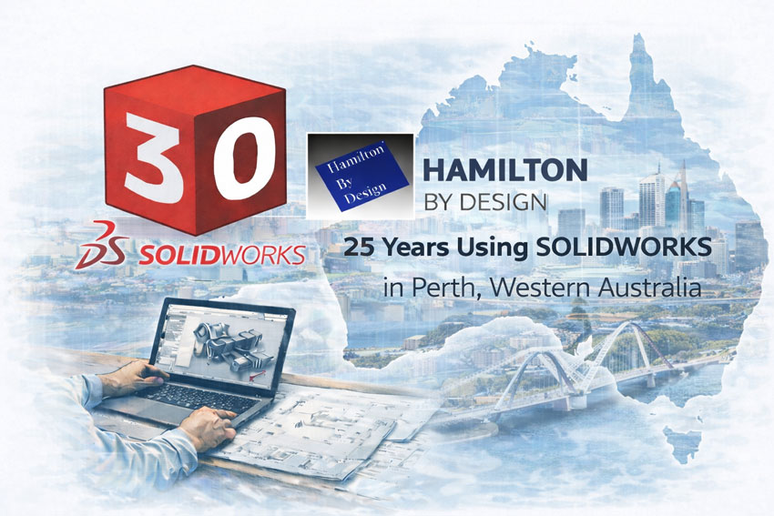
SolidWorks 30 years cube with Hamilton By Design highlighting 25 years of SolidWorks use in Perth, Western Australia

Need Extra Drafting Capacity? Secondment Available

If your Perth team needs extra drafting capacity integrated into your workflow, we also offer engineering-led secondment services.

Learn more about Secondment Services

Secondment is ideal for:

  • Fabricators scaling up for tenders
  • Project teams during peak design / drafting loads
  • Shutdown and brownfield upgrade packages requiring close coordination

Industries We Commonly Support Around Perth

We support SolidWorks drafting and engineering documentation for:

  • Mining services and resources contractors
  • Oil & gas / energy infrastructure
  • Fabrication and structural steel workshops
  • Ports, logistics, and bulk handling facilities
  • Manufacturing and industrial maintenance teams

Whether youโ€™re in Perth metro, Kwinana, Henderson, or supporting regional WA operations, we can deliver drafting support with clear scope and disciplined outputs.


Our clients:


How We Differ From Drafting-Only Providers

Many drafting vendors deliver CAD files but do not own fit-up risk.

Hamilton By Design provides:
  • Engineering ownership, not drafting in isolation
  • Fabrication-aware drawings aligned to real build constraints
  • Better interface clarity and reduced interpretation risk
  • Accountable outputs suited to procurement, fabrication, and installation

This is drafting designed to perform on site.


Hamilton By Design logo displayed on a blue tilted rectangle with a grey gradient background
3D LiDAR scanning and 3D modelling service button โ€” laser scanner capturing a point cloud for engineering and CAD modelling
Mechanical engineering services

Speak With an Engineer About SolidWorks Drafting in Perth

If youโ€™re looking for SolidWorks drafting support in Perth โ€” whether as a defined drafting package or embedded secondment โ€” letโ€™s talk early and reduce risk before fabrication begins.

Use the contact form below to discuss your Perth SolidWorks drafting requirements.

Name
Would you like us to arrange a phone consultation for you?
Address


https://www.hamiltonbydesign.com.au/perth-wa
Mechanical Engineering Perth WA banner for Hamilton By Design featuring white text on a blue background.
3D Laser Scanning Perth WA banner for Hamilton By Design with white text on a blue background.
SolidWorks Perth WA banner for Hamilton By Design featuring white text on a blue background.
3D LiDAR scanning and 3D modelling service button โ€” laser scanner capturing a point cloud for engineering and CAD modelling
Mechanical engineering services
https://www.hamiltonbydesign.com.au/perth-wa

3D CAD Modelling Australia service banner for Hamilton By Design


CHPP Engineering title graphic featuring bold white text reading "CHPP Engineering" centred on a blue rounded rectangle background.
Pipework Drafting title graphic featuring bold white text reading "Pipework Drafting" centred on a blue rounded rectangle background.
3D LiDAR Scanning for Engineering Projects title graphic featuring bold white text on a blue rounded rectangle background.


Finite Element Analysis (FEA) engineering simulation button
Structural drafting services button
Mechanical drafting services button


Australian Drafting logo featuring bold white text reading "Australian Drafting" centred on a blue rounded rectangle background.
Engineering Governance title graphic featuring bold white text reading "Engineering Governance" centred on a blue rounded rectangle background.
Engineering-Grade LiDAR Scanning title graphic featuring bold white text on a blue rounded rectangle background.


Mechanical drafting services button
Structural drafting services button


Fabrication and product design services
3D CAD Modelling Australia service banner for Hamilton By Design
Mechanical, Structural & Pipework Drafting service banner by Hamilton By Design featuring white text on a blue background.


3D LiDAR scanning and 3D modelling service button โ€” laser scanner capturing a point cloud for engineering and CAD modelling
Mechanical engineering services
Mining & Processing Perth WA banner for Hamilton By Design featuring white text on a blue background.
Scan to BIM Perth WA banner for Hamilton By Design featuring white text on a blue background.
Ship Building Perth WA banner for Hamilton By Design featuring white text on a blue background.
Structural drafting services button
3D LiDAR scanning and 3D modelling services button
Mechanical drafting services button