Mechanical Engineering | 3D Scanning | 3D Modelling
Tag: as-built-drawings
Hamilton By Design prepares as-built drawings for industrial facilities, buildings, machinery and fixed plant using 3D LiDAR scanning and site measurements.
As-built drawings document the position, dimensions and arrangement of assets as they exist at the time of capture. They are particularly valuable where original drawings are incomplete, unavailable or no longer reflect modifications made during construction, installation or ongoing plant operation.
Our services can include site scanning, point-cloud registration, dimensional verification and the preparation of:
Existing-condition plans and elevations
Equipment and machinery layouts
General arrangement drawings
Building and facility layouts
Pipework and service arrangements
Platforms, walkways and access systems
Industrial plant and structural-steelwork drawings
Roof, façade and floor-level documentation
The registered point cloud provides a measurable spatial reference from which the agreed features can be traced and documented. The required scope, accuracy, drawing scale and level of detail should be confirmed before drafting begins.
Deliverables may include PDF drawing packages, AutoCAD-compatible DWG or DXF files, registered E57 or RCP point clouds and associated 3D CAD or BIM models.
As-built drawings record the visible and accessible conditions captured during the survey. Concealed services, internal construction details and inaccessible areas cannot be confirmed unless suitable additional information or investigation is provided.
It sounds like a line from a dispute you would rather avoid. But a staircase, lift, custom joinery package or new opening can be designed around dimensions that looked reasonable on a drawing and still fail to fit the finished space.
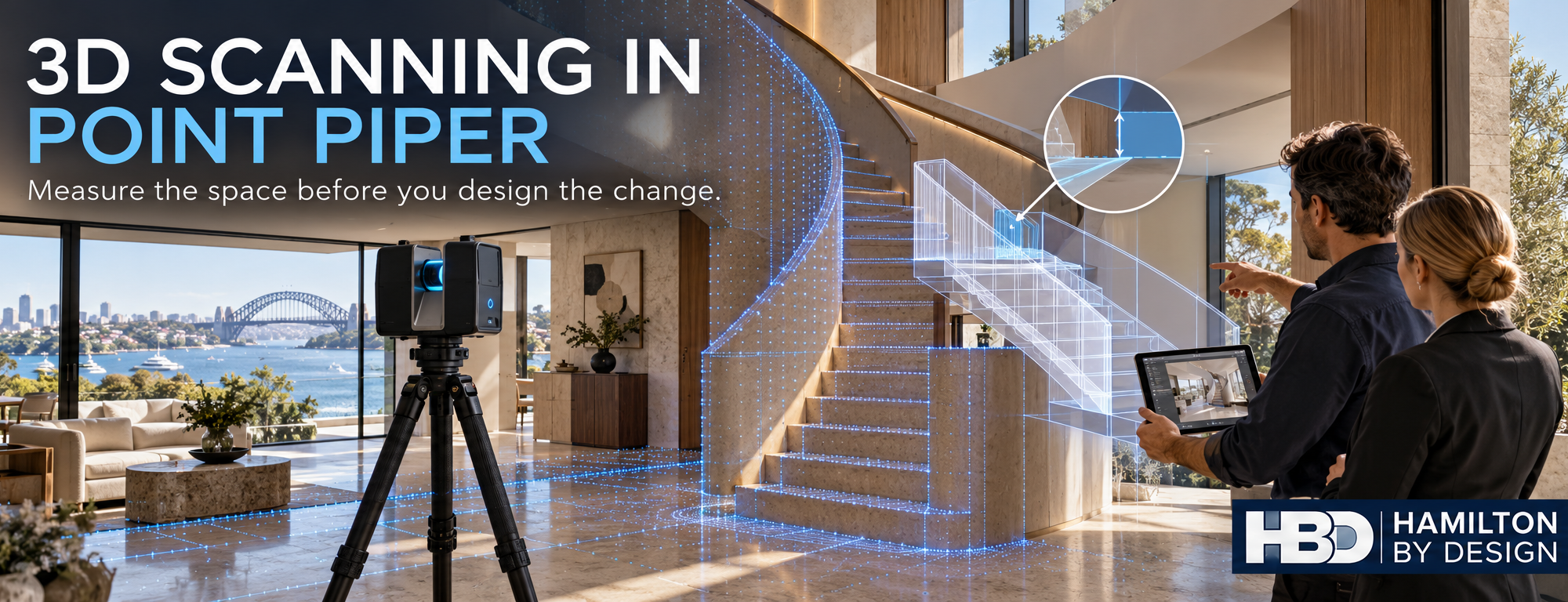
If you are planning changes to a property in Point Piper, the first step is to understand its existing geometry. Hamilton By Design uses stationary 3D LiDAR scanning to capture visible walls, floors, ceilings, stairs and building services. The registered point cloud can then support measured drawings and 3D models for design and coordination. LiDAR & 3D Modelling
A property tour and a design record serve different purposes
A 3D tour can help prospective buyers explore a property online. It is a useful presentation tool, but an attractive walkthrough should not automatically become the dimensional basis for a renovation.
For design work, the questions are more specific: How much clear space is available? Are the walls square? Where does the ceiling change height? Will the proposed stair, lift or joinery fit alongside the existing structure and services?
A stationary terrestrial scanner can capture detailed geometry from planned scan positions. Mobile SLAM scanning can document spaces quickly and may be suitable for broader layout work. The accuracy and detail available from either method depend on the equipment, site conditions, capture method and processing. A published comparison found both methods useful for building documentation, while the stationary scanner provided better detail for intricate features in the study. isprs-archives.copernicus.org
Where better measurements can make a difference
For a Point Piper property, an as built scan may help an architect, builder or specialist supplier plan:
A replacement staircase or altered stair opening
A lift or access upgrade
Kitchen, bathroom and custom joinery work
Changes to ceiling heights or service routes
Plant room and building services upgrades
A refurbishment that must connect neatly to existing construction
The value is in capturing the areas that matter to the proposed change, then checking critical dimensions before anything is fabricated. A scan provides a detailed record of visible surfaces; concealed construction still needs to be investigated, and critical interfaces should be verified for their intended use.
Consider the cost of getting the starting dimensions wrong
A lower cost scan may be entirely suitable when the goal is a visual record or an approximate layout. When a component must fit an existing opening, the useful question is whether the capture and checking process meets the project’s required tolerance.
Finding a clash during design gives the team options. Finding it when a finished staircase arrives on site can mean redesign, modification and delay. The scanner alone does not guarantee a successful fit: scan planning, registration, interpretation and final dimensional checks all matter. Research on terrestrial laser scanning likewise identifies several sources of measurement error that must be considered when using scan data for dimensional work. NIST
From Point Piper property scan to practical design information
Hamilton By Design can capture the existing space and provide a registered point cloud for review. Where required, that data can be developed into CAD drawings or a 3D model for the design team, fabricator or installer. The scope should identify the proposed alteration and the dimensions that need particular attention before scanning begins. Hamilton By Design Co.
If the project requires a legal property boundary survey, engage a registered land surveyor. A building scan does not determine title boundaries; in NSW, boundary surveys are the work of registered land surveyors. Automatic Mutual Recognition (AMR)
Planning a renovation or property upgrade in Point Piper?Contact Hamilton By Design with your plans and the proposed changes. We can discuss what needs to be captured so your design team starts with a useful record of the existing property.
3D Scanning in Point Piper: Plan Property Changes Around What Is Actually There
“Your Honour, the stairs did not fit.”
It sounds like a line from a dispute you would rather avoid. But a staircase, lift, custom joinery package or new opening can be designed around dimensions that looked reasonable on a drawing and still fail to fit the finished space.
If you are planning changes to a property in Point Piper, the first step is to understand its existing geometry. Hamilton By Design uses stationary 3D LiDAR scanning to capture visible walls, floors, ceilings, stairs and building services. The registered point cloud can then support measured drawings and 3D models for design and coordination. LiDAR & 3D Modelling
A property tour and a design record serve different purposes
A 3D tour can help prospective buyers explore a property online. It is a useful presentation tool, but an attractive walkthrough should not automatically become the dimensional basis for a renovation.
For design work, the questions are more specific: How much clear space is available? Are the walls square? Where does the ceiling change height? Will the proposed stair, lift or joinery fit alongside the existing structure and services?
A stationary terrestrial scanner can capture detailed geometry from planned scan positions. Mobile SLAM scanning can document spaces quickly and may be suitable for broader layout work. The accuracy and detail available from either method depend on the equipment, site conditions, capture method and processing. A published comparison found both methods useful for building documentation, while the stationary scanner provided better detail for intricate features in the study. isprs-archives.copernicus.org
Where better measurements can make a difference
For a Point Piper property, an as built scan may help an architect, builder or specialist supplier plan:
A replacement staircase or altered stair opening
A lift or access upgrade
Kitchen, bathroom and custom joinery work
Changes to ceiling heights or service routes
Plant room and building services upgrades
A refurbishment that must connect neatly to existing construction
The value is in capturing the areas that matter to the proposed change, then checking critical dimensions before anything is fabricated. A scan provides a detailed record of visible surfaces; concealed construction still needs to be investigated, and critical interfaces should be verified for their intended use.
Consider the cost of getting the starting dimensions wrong
A lower cost scan may be entirely suitable when the goal is a visual record or an approximate layout. When a component must fit an existing opening, the useful question is whether the capture and checking process meets the project’s required tolerance.
Finding a clash during design gives the team options. Finding it when a finished staircase arrives on site can mean redesign, modification and delay. The scanner alone does not guarantee a successful fit: scan planning, registration, interpretation and final dimensional checks all matter. Research on terrestrial laser scanning likewise identifies several sources of measurement error that must be considered when using scan data for dimensional work. NIST
From Point Piper property scan to practical design information
Hamilton By Design can capture the existing space and provide a registered point cloud for review. Where required, that data can be developed into CAD drawings or a 3D model for the design team, fabricator or installer. The scope should identify the proposed alteration and the dimensions that need particular attention before scanning begins. Hamilton By Design Co.
If the project requires a legal property boundary survey, engage a registered land surveyor. A building scan does not determine title boundaries; in NSW, boundary surveys are the work of registered land surveyors. Automatic Mutual Recognition (AMR)
Planning a renovation or property upgrade in Point Piper?Contact Hamilton By Design with your plans and the proposed changes. We can discuss what needs to be captured so your design team starts with a useful record of the existing property.
3D Laser Scanning Yennora: Accurate As-Built Data for Warehouses, Manufacturing and Logistics
Yennora is one of Western Sydney’s most established industrial and distribution precincts. Its combination of large warehouses, manufacturing facilities, intermodal freight infrastructure, food production, healthcare distribution, building-product storage and recycling operations creates a complex operating environment.
Many facilities have been modified repeatedly as tenants, machinery, production requirements and logistics systems have changed. Original drawings may no longer represent the physical site. This becomes a significant problem when installing machinery, extending conveyors, modifying racking or planning a warehouse redevelopment.
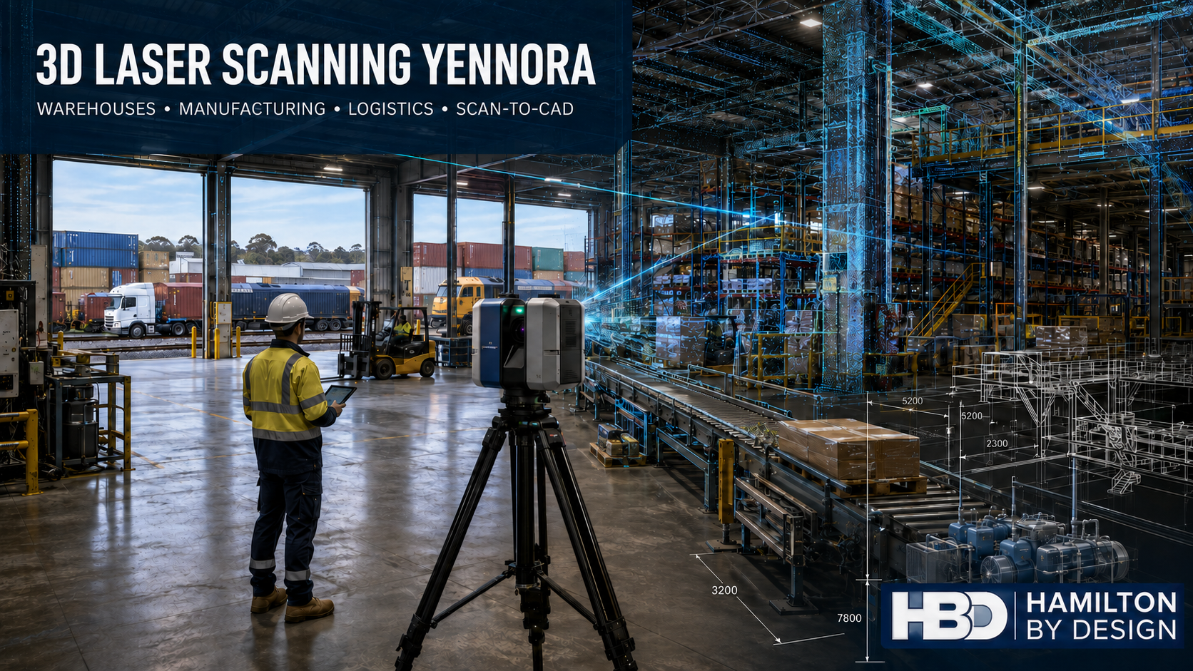
Hamilton By Design provides 3D laser scanning for engineering projects in Yennora and throughout Western Sydney. The service captures existing industrial conditions and converts them into point clouds, CAD models, equipment layouts and as-built drawings suitable for engineering and project planning.
Yennora’s industrial character
Yennora’s industrial area supports a broad range of activities, including:
Rail and road freight
Container handling and storage
Contract logistics
Food manufacturing and packaging
Refrigerated warehousing
Healthcare-product distribution
Building-material storage
Warehouse picking and dispatch
Recycling and waste processing
Furniture removals and storage
The Yennora Distribution Centre is a major rail-connected logistics estate containing extensive warehouse and container-handling facilities. Other parts of Yennora contain established factories, workshops, production facilities and smaller industrial premises.
These sites commonly contain racking, loading docks, conveyors, refrigeration equipment, machinery, structural steel, platforms, mobile plant and building services. Understanding how these elements relate spatially is essential before any modification begins.
Why accurate existing-condition information matters
Traditional site measurement remains useful for individual dimensions. However, it becomes difficult when a project involves an entire warehouse, production line or interconnected group of machines.
A tape measure records only the dimensions selected during the inspection. If another measurement becomes necessary later, the project team may need to return to the site. It can also be difficult to measure congested areas, overhead services and operating machinery safely.
Engineering-led 3D laser scanning captures millions of coordinated points representing visible surfaces. The resulting point cloud provides a measurable three-dimensional record of the facility at the time of scanning.
Designers can revisit the data throughout the project to examine:
Column and wall positions
Floor levels and roof clearances
Machinery locations
Conveyor routes
Racking arrangements
Platforms and access systems
Pipework and building services
Loading docks and roller doors
Maintenance and installation clearances
This reduces reliance on assumptions and allows proposed work to be checked against the existing facility before fabrication begins.
Five common problems within established industrial facilities
1. Drawings do not match the physical site
Warehouses and factories change over time. Equipment may be relocated, platforms extended and services rerouted without the original drawings being revised.
Scanning creates a new existing-condition baseline. The point cloud can be compared with old drawings to identify significant differences before design work proceeds.
2. Production cannot stop for extended measurement
Many Yennora businesses operate under demanding production and delivery schedules. Closing an area for conventional measurement may be impractical.
LiDAR is a non-contact measurement method that can capture large areas efficiently. Scanning can often be staged around access restrictions, operating shifts and loading activities. This does not remove the need for site safety controls, but it can reduce the time personnel spend close to operating plant.
3. New equipment clashes with existing infrastructure
A new conveyor, packaging machine or access platform may appear suitable on a general layout but clash with a column, service, handrail or maintenance zone during installation.
Hamilton By Design’s warehouse and conveyor scanning services allow proposed equipment to be positioned within the scanned environment. SolidWorks and Navisworks can then be used to review clearances and identify potential conflicts.
4. Brownfield layouts are difficult to interpret
Established factories rarely have simple layouts. Multiple extensions, previous projects and different construction methods can produce irregular structural and mechanical interfaces.
A coordinated point cloud allows the project team to examine the entire area rather than treating each component in isolation. Sections, elevations and local views can be extracted wherever additional information is required.
5. Facility information is fragmented
Property owners, tenants, maintenance teams and contractors may hold different versions of the same layout. Some information may exist only as marked-up PDFs or old AutoCAD files.
A controlled point cloud and CAD model provide a shared dimensional reference. This information can later support maintenance, asset replacement and additional modifications.
From site scanning to engineering information
The Hamilton By Design workflow begins by defining why the facility is being scanned. A warehouse survey intended for a tenancy record may require different detail from a scan supporting a conveyor installation.
The site is captured using terrestrial or mobile LiDAR equipment. Scan positions are registered in FARO SCENE to form a coordinated point cloud. The data can then be exported into formats suitable for Autodesk ReCap, AutoCAD, Navisworks and other engineering systems.
Depending on the project, deliverables may include:
Registered point clouds
Existing-condition plans
Factory and warehouse layouts
Machinery and equipment layouts
Sections and elevations
AutoCAD DWG or DXF files
SolidWorks parts and assemblies
STEP or Parasolid models
General arrangement drawings
Fabrication drawings
Bills of materials
PDF drawing packages
Hamilton By Design uses SolidWorks for mechanical design and modelling to convert measured site information into practical assemblies and drawings. This creates a direct connection between site reality and the proposed engineering solution.
Mechanical engineering for manufacturing and logistics
Scanning identifies geometry, but engineering is still required to determine whether a proposed modification is safe, functional and suitable for service.
Hamilton By Design provides mechanical engineering consulting for production equipment, materials-handling systems, plant modifications and brownfield projects.
Hamilton By Design also provides manufacturing and production engineering support for facilities experiencing recurring jams, poor equipment access, unsuitable layouts or unreliable transfer points.
Mechanical drafting and fabrication documentation
Accurate drawings are essential once a design is ready for manufacture or installation. Hamilton By Design’s mechanical drafting services can develop:
Mechanical general arrangements
Manufacturing drawings
Assembly and detail drawings
Conveyor and equipment layouts
Chute and hopper drawings
Structural-support details
Installation drawings
Weldment drawings
DXF cutting profiles
Parts lists and bills of materials
As-built documentation
Drawing presentation may be prepared in accordance with AS 1100 technical-drawing conventions. Structural drafting can also consider AS/NZS 1100.501, while relevant designs may require assessment against AS 4100, AS/NZS 1170 and AS/NZS 1554.1.
The applicable standards depend on the equipment, loads, materials, site requirements and intended use.
Safety and risk-management support
Industrial modifications can introduce risks if machinery, people and mobile plant are considered separately. Hamilton By Design can use scan data to support design-risk reviews addressing:
Conveyor nip and entanglement points
Machine guarding
Maintenance access
Unexpected machine start-up
Emergency-stop access
Forklift and pedestrian interaction
Working at height
Lifting and component removal
Restricted clearances
Access around operating equipment
The AS/NZS 4024 series provides an important framework for machinery safety. Conveyor systems may require consideration of AS/NZS 4024.3610, AS/NZS 4024.3611 or AS/NZS 4024.3612. Platforms, walkways, stairs and ladders may require assessment against AS 1657.
Hamilton By Design’s discussion of machine guarding in Australian industry explains why guarding should consider operation, cleaning, inspection and maintenance rather than simply placing a barrier around moving machinery.
For logistics facilities, scanning can also support forklift routes, pedestrian walkways, loading zones and barrier layouts. Steel storage racking may require consideration of AS 4084, while powered industrial trucks are addressed through the AS 2359 series.
Risk management should follow the hierarchy of controls, with elimination, substitution, isolation and engineering controls considered before relying on procedures or personal protective equipment. The site operator retains responsibility for its WHS system, worker consultation, training and operational procedures.
Retaining a reliable facility record
The value of scanning can continue after the original project is complete. Hamilton By Design can retain warehouse point clouds, equipment layouts, conveyor arrangements, CAD models and as-built drawings as a reference for future work.
Information can also be organised using principles described in ISO 19650 and Scan-to-BIM information management. A controlled information structure makes it easier to identify the current model, drawing revision and original source data.
Frequently asked questions
What is 3D laser scanning used for in a Yennora warehouse?
It can capture the warehouse structure, racking, loading docks, machinery, conveyors and visible services. The data can support layouts, equipment installations, tenancy changes and as-built documentation.
Can scanning be completed while a facility remains operational?
Often, yes. The work must be planned around site traffic, machinery, restricted areas and operational requirements. Access and safety arrangements should be confirmed before scanning begins.
Does a point cloud replace engineering drawings?
No. A point cloud is a measured representation of visible conditions. CAD modelling and drafting are normally required to convert it into controlled plans, equipment models or fabrication drawings.
Can Hamilton By Design design conveyor modifications?
Yes. Hamilton By Design can support conveyor layouts, transfer points, mechanical modifications, equipment integration, guarding and associated drafting, subject to the defined engineering scope.
Can old drawings be checked against the current factory?
Yes. Existing drawings can be compared with the registered point cloud to identify changes, missing equipment and dimensional differences.
What file formats can be supplied?
Typical deliverables include E57, RCP, RCS, DWG, DXF, STEP, Parasolid, SolidWorks and PDF. The required formats should be agreed before the project begins.
Can the scan data be retained for future projects?
Yes. The point cloud and derived CAD information can form a long-term existing-condition record, reducing the need to resurvey unchanged areas.
Does scanning prove that equipment complies with Australian Standards?
No. Scanning provides dimensional evidence. Engineering assessment is still required to consider loads, materials, guarding, structural capacity, operational risks and the standards applicable to the specific project.
Engineering-Grade 3D Laser Scanning for Food, Beverage, Packaging and Fast-Moving Manufacturing Facilities
Fast-moving consumer goods manufacturing is built around production.
Food, beverage, packaging and consumer-product facilities depend on machinery, conveyors, pipework, utilities, structural steel and automated systems operating together in increasingly congested production environments.
The challenge is that these facilities rarely remain exactly as they were originally designed.
Production lines change. New machinery is installed. Conveyors are extended. Pipework is rerouted. Packaging systems are replaced. Platforms are modified. Automation is introduced. Utilities are relocated.
Over time, the physical factory can become significantly different from the drawings available to the engineering team.
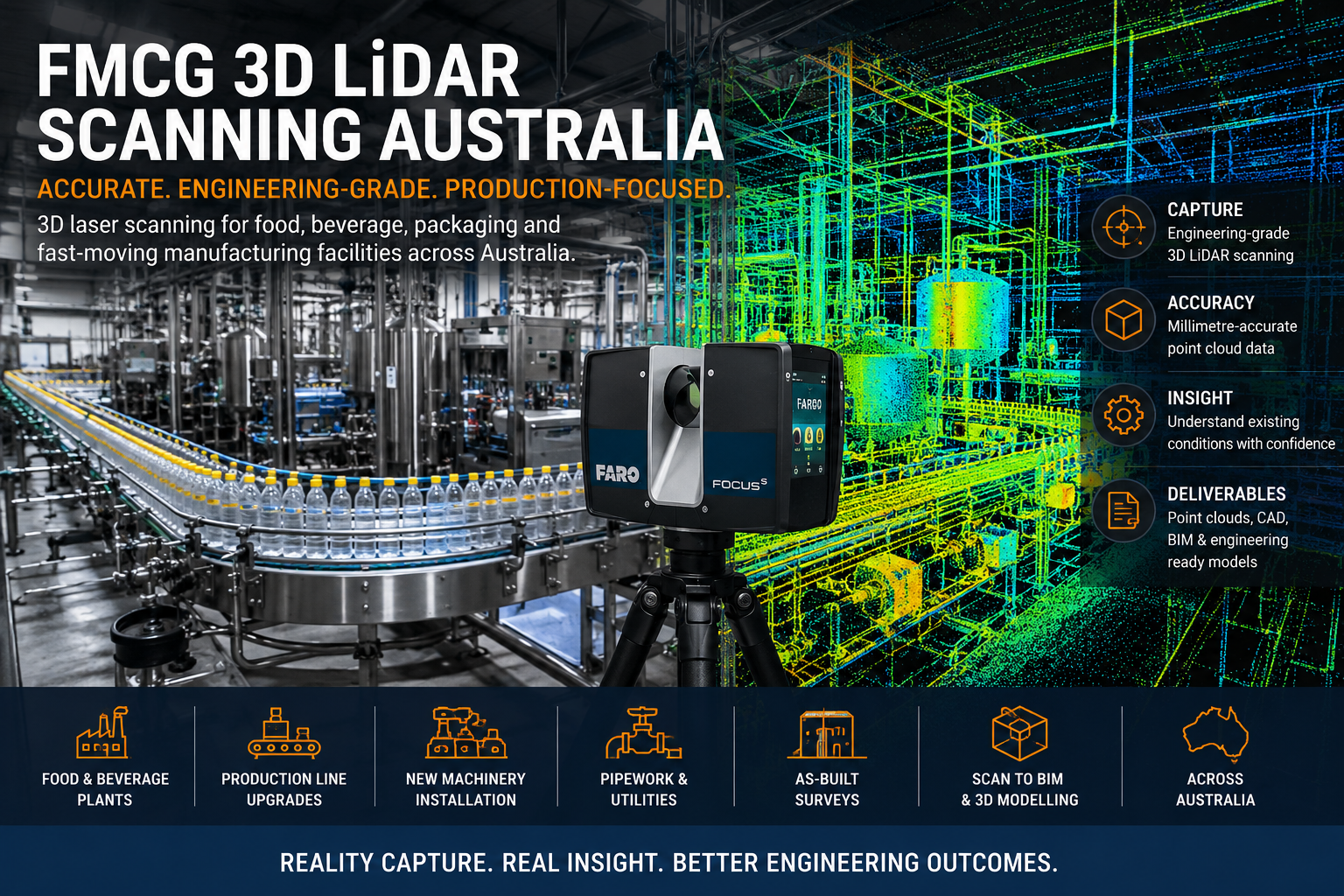
Hamilton By Design provides FMCG 3D LiDAR scanning services across Australia, capturing accurate existing factory conditions to support production-line upgrades, machinery installation, plant modifications, engineering design and as-built documentation.
Our approach combines engineering-grade reality capture with mechanical engineering, 3D CAD modelling and drafting so the captured data can be used to solve practical industrial problems.
For projects requiring the captured factory to be developed into coordinated BIM or digital models, see our Factory Scan to BIM Australia service.
The Biggest Problem: The Factory Changes Faster Than the Drawings
One of the biggest engineering problems within an FMCG facility is not necessarily the machinery itself.
It is knowing exactly what is already there.
Food, beverage and consumer-goods factories can undergo numerous modifications during their operating life.
Individual projects may alter:
production machinery;
conveyors;
packaging lines;
pipework;
valves;
pumps;
ducting;
structural steel;
access platforms;
guarding;
cable trays;
electrical services;
compressed-air systems;
process utilities;
equipment foundations; and
maintenance access.
Those changes are not always incorporated into the original drawings.
The result is a familiar brownfield engineering problem:
Tomorrow’s production equipment may be designed using yesterday’s factory information.
In an FMCG environment, this becomes particularly important because installation work may need to occur during tightly controlled shutdown periods.
If a new machine, conveyor, platform, pipe spool or structural component does not fit when it arrives on site, the problem can quickly become more than an engineering inconvenience.
It can affect production.
3D LiDAR scanning helps reduce this uncertainty by creating a measurable digital record of the facility as it exists today.
What Is FMCG 3D LiDAR Scanning?
3D LiDAR scanning uses laser measurements to capture the geometry of an existing factory, production line or industrial environment.
Multiple scanner positions can be combined to create a registered 3D point cloud representing the physical facility.
The point cloud can capture the spatial relationship between:
machinery;
conveyors;
pipework;
platforms;
structures;
services;
equipment;
access areas; and
surrounding building geometry.
Hamilton By Design’s 3D Laser Scanning for Engineering Projects service is focused on using captured site information as an engineering resource rather than simply producing a visual scan.
Depending on the project, the resulting information can support:
3D CAD modelling;
Scan to BIM;
equipment layout design;
general arrangement drawings;
existing-condition documentation;
clash assessment;
mechanical design;
fabrication planning; and
installation engineering.
Why 3D Scan an FMCG Factory?
Traditional site measurement can work well when only a small number of dimensions are required.
The difficulty arises when a project has to interact with an entire production environment.
A single equipment installation may need to account for:
floor levels;
surrounding machinery;
access clearances;
structural columns;
overhead steelwork;
pipework;
cable trays;
conveyors;
maintenance access;
operator access;
hygiene zones; and
installation pathways.
Rather than attempting to predict every dimension that may be required later, 3D laser scanning captures a broader representation of the existing environment.
This provides engineers with a digital reference that can be reviewed after the site visit.
For broader manufacturing and industrial projects, Hamilton By Design also provides 3D Laser Scanning for Industrial Plants, combining plant capture with point-cloud-to-CAD, Scan to BIM and engineering applications.
3D Scanning for Food Manufacturing Plants
Food manufacturing facilities can contain complex combinations of processing machinery, conveyors, pipework, tanks, vessels, platforms and building services.
A proposed upgrade may need to integrate into an operating environment where space is already heavily utilised.
3D LiDAR scanning can support projects involving:
process-line modifications;
new production equipment;
conveyor changes;
packaging-line upgrades;
pipework modifications;
plant-room alterations;
new platforms and access;
utility changes; and
factory redevelopment.
Existing-condition capture can be particularly valuable where the original drawings are incomplete or numerous plant changes have occurred over time.
Hamilton By Design already supports food, beverage and manufacturing businesses through its broader Mechanical Engineering Services on the Central Coast, including plant upgrades, component replacement and 3D LiDAR scanning.
3D Laser Scanning for Beverage Plants
Beverage-production facilities often combine process equipment with extensive pipework, tanks, conveyors, filling machinery and packaging systems.
A relatively small modification can therefore involve several engineering interfaces.
Typical applications may include:
bottling-line modifications;
filling equipment;
tank installations;
process pipework;
conveyor rerouting;
packaging equipment;
palletising systems;
structural platforms;
access modifications; and
service coordination.
Capturing the surrounding environment before design begins provides a more reliable basis for positioning new equipment and identifying potential conflicts.
Packaging-Line 3D Scanning
Packaging lines can involve closely integrated machinery operating within limited floor space.
Equipment may include:
fillers;
cappers;
labellers;
wrappers;
case packers;
carton systems;
conveyors;
inspection equipment;
palletisers; and
robotic handling systems.
When one piece of machinery is replaced, the new equipment may still have to connect with the existing upstream and downstream production systems.
3D scanning can capture those interfaces so the engineering team can assess the available space before the replacement equipment is installed.
Production-Line Modifications
Production lines evolve.
New products may require different machinery.
Higher throughput may require new conveying systems.
Manual operations may be automated.
Existing machines may need to move.
The surrounding factory does not necessarily move with them.
This means a production-line modification may have to fit between existing machinery, structural columns, platforms, services and access areas.
An engineering-grade point cloud can provide the design team with an accurate reference for developing the revised production layout.
For projects where a full digital representation of the factory is required, our Factory Scan to BIM Australia service can convert existing-condition capture into practical BIM and CAD information for factory upgrades.
New Machinery and Equipment Installation
Installing new equipment into an existing FMCG factory is fundamentally different from placing machinery in an empty building.
The proposed machine may need to fit around:
existing production equipment;
conveyors;
structural steel;
services;
access routes;
maintenance zones;
existing foundations;
floor penetrations;
overhead obstructions; and
operator working areas.
3D scanning before detailed design can help establish these interfaces.
The proposed equipment can then be modelled within the captured environment.
This can assist the engineering team in answering practical questions such as:
Will the machine fit?
Can it be installed?
Can it be maintained once installed?
Will existing equipment obstruct access?
Do surrounding services need to move?
Will the new conveyor align with the existing production line?
Brownfield Engineering for FMCG Facilities
Most existing FMCG upgrade projects are brownfield projects.
The new engineering has to work around what already exists.
This may include equipment installed decades earlier, later modifications, undocumented steelwork, relocated services and machinery that cannot easily be moved.
Hamilton By Design’s broader Engineering Services combine reality capture with mechanical engineering, modelling and drafting for brownfield and retrofit projects.
The advantage of integrating scanning with engineering is that the scanning strategy can be developed around what the project team actually needs to design.
The purpose is not simply to capture everything.
The purpose is to capture the information required to make better engineering decisions.
FMCG Factory As-Built Surveys
Accurate as-built documentation can be difficult to maintain in a continuously evolving production facility.
Drawings may show what was originally installed rather than what exists today.
A LiDAR-based as-built survey can create a new spatial reference for the factory.
This may be useful where:
drawings are unavailable;
existing drawings are outdated;
equipment has moved;
pipework has changed;
platforms have been added;
production systems have been modified;
multiple contractors have changed the facility; or
future upgrades are being planned.
For larger digital documentation projects, Hamilton By Design’s national Scan to BIM Australia services provide a pathway from measured reality to structured digital models.
Scan Before the Shutdown
Production shutdowns can represent one of the most expensive periods of an FMCG engineering project.
The installation window may be fixed while numerous contractors and activities compete for access.
Where practical, scanning before the shutdown allows engineering work to begin while the plant is still operating.
A typical workflow can become:
3D Site Scanning
↓
Point-Cloud Registration
↓
Existing-Condition Review
↓
3D CAD Modelling
↓
Engineering Design
↓
Fabrication Planning
↓
Shutdown Installation
The more engineering that can be completed before the shutdown begins, the less work needs to be resolved while production is offline.
Hamilton By Design’s 3D Laser Scanning for Engineering service is specifically focused on using accurate existing-condition data to support brownfield upgrades, shutdown engineering and fabrication planning.
Conveyor and Materials-Handling 3D Scanning
Conveyors are common throughout FMCG production and packaging systems.
They may connect several machines across a production line and frequently pass beneath or around existing structures and services.
3D scanning can capture:
conveyor centre lines;
conveyor elevations;
support frames;
transfer locations;
machinery interfaces;
surrounding structures;
access areas;
guarding;
platforms; and
overhead restrictions.
This information can support conveyor extensions, production-line changes and new machinery integration.
Pipework, Utilities and Factory Services
Food, beverage and FMCG plants can contain extensive networks of mechanical and electrical services.
Depending on the facility, these may include:
process pipework;
compressed air;
water;
steam;
cleaning systems;
drainage;
electrical services;
cable trays;
ventilation;
ducting; and
equipment utilities.
These services often occupy congested spaces above, below and around production equipment.
3D laser scanning provides a way to capture their spatial relationship to the surrounding factory.
The resulting point cloud can then support routing studies, plant modifications and equipment connections.
Structural Steel, Platforms and Access
New equipment does not exist independently of the surrounding structure.
Manufacturing facilities may contain:
structural columns;
beams;
roof trusses;
equipment support structures;
platforms;
stairs;
handrails;
equipment frames;
walkways; and
mezzanines.
Capturing this geometry provides engineers with a reference when developing equipment layouts or assessing structural interfaces.
From FMCG Point Cloud to CAD and BIM
The registered point cloud is only the starting point.
Depending on the project requirement, captured factory information can be converted into engineering geometry.
This may include:
SolidWorks models;
AutoCAD drawings;
BIM models;
equipment layouts;
mechanical arrangements;
structural interfaces;
sections and elevations;
general arrangement drawings;
fabrication reference geometry; and
existing-condition models.
Hamilton By Design’s Scan to BIM Sydney service demonstrates the broader workflow of combining LiDAR scanning with BIM to establish accurate digital representations for design, maintenance and asset-management applications.
Engineer-Led FMCG 3D Scanning
A factory can be scanned in many different ways.
The most appropriate scanning strategy depends on what the project needs to achieve.
An engineering-led approach considers questions such as:
What is being modified?
Which interfaces are critical?
What equipment is being replaced?
Which dimensions will matter during installation?
Does the surrounding structure need to be modelled?
What CAD system will be used?
Does fabrication need to occur before the shutdown?
Which areas are difficult to access?
What level of modelling is actually required?
Hamilton By Design combines 3D scanning with mechanical engineering and design experience so the scanning scope can be developed around the downstream engineering requirement.
FMCG 3D LiDAR Scanning Across Australia
Hamilton By Design provides FMCG, factory and industrial 3D laser scanning services for projects across Australia.
We can support projects in:
Sydney;
Newcastle;
Central Coast NSW;
Wollongong;
Brisbane;
Gold Coast;
Melbourne;
Adelaide;
Perth;
Darwin;
regional NSW;
regional Queensland;
regional Victoria;
regional South Australia;
regional Western Australia; and
other industrial locations throughout Australia.
For broader national reality-capture requirements, see our 3D Laser Scanning services.
FMCG Industries We Can Support
3D LiDAR scanning can support a wide range of fast-moving manufacturing environments, including:
food manufacturing;
beverage production;
dairy processing;
bakeries;
bottling plants;
breweries;
confectionery;
frozen-food production;
meat processing;
packaging plants;
consumer-product manufacturing;
personal-care manufacturing;
household-product manufacturing;
warehousing;
logistics;
automated production;
palletising facilities; and
general manufacturing.
The common requirement is an existing production environment where new engineering must fit around the real facility.
Typical FMCG 3D Scanning Deliverables
Project deliverables can be tailored to suit the downstream engineering workflow and may include:
registered 3D point clouds;
E57 files;
RCP/RCS datasets;
LAS files;
3D CAD models;
BIM models;
SolidWorks models;
STEP files;
SAT files;
AutoCAD DWG files;
DXF files;
general arrangement drawings;
sections;
elevations;
equipment layouts;
existing-condition plans; and
engineering documentation.
Not every project requires every deliverable.
The appropriate output should be determined by what the engineering team needs to achieve.
Frequently Asked Questions
What is FMCG 3D LiDAR scanning?
FMCG 3D LiDAR scanning uses laser-based reality capture to document the existing geometry of food, beverage, packaging and consumer-goods manufacturing facilities. The resulting point cloud can support engineering, CAD, BIM and plant-upgrade projects.
Can you scan an operating food or manufacturing factory?
Many facilities can be scanned while normal operations continue, subject to site safety requirements, access restrictions and the nature of the production process.
Can production machinery be included in the scan?
Yes. Machinery, conveyors, structural steel, platforms, services, pipework and surrounding building geometry can be captured according to the requirements of the project.
Can scanning help before installing new machinery?
Yes. Capturing the surrounding environment before equipment installation allows the proposed machinery and its interfaces to be evaluated against existing factory geometry.
Can you scan conveyor systems?
Yes. Conveyor geometry, supports, interfaces, transfers, surrounding structures and associated equipment can be included in the scan.
What happens if our factory drawings are outdated?
This is one of the main reasons to consider reality capture. 3D scanning records the existing physical condition rather than relying entirely on legacy drawings.
Can FMCG scan data be used for Scan to BIM?
Yes. Where required, point-cloud information can be developed into BIM or CAD models. See our Factory Scan to BIM Australia service for more information.
Can the scan data be used in SolidWorks?
Point-cloud information can be used as reference data for developing appropriate engineering geometry for SolidWorks workflows.
Do you provide FMCG 3D scanning outside Sydney?
Yes. Hamilton By Design supports 3D laser scanning and engineering projects throughout Australia.
Planning an FMCG Factory Upgrade?
A successful factory modification starts with understanding what is already there.
Before designing a new production line, installing machinery, modifying conveyors or fabricating equipment around old drawings, capture the existing facility accurately.
Hamilton By Design provides FMCG 3D LiDAR scanning, Factory Scan to BIM, mechanical engineering, 3D modelling and drafting services across Australia.
Our goal is to provide engineering teams with a reliable digital starting point for brownfield projects where fit, access, interfaces and shutdown duration matter.
Capture the existing factory. Understand the interfaces. Engineer the upgrade around reality.
Related FMCG, Factory 3D Scanning & Engineering Services
Explore additional Hamilton By Design services supporting food, beverage,
packaging and manufacturing facilities with 3D LiDAR scanning, Scan to BIM,
point-cloud modelling, reverse engineering and brownfield plant upgrades.
Engineering-Grade 3D Laser Scanning for Manufacturing Plants, Processing Facilities and Brownfield Factory Upgrades
Factories rarely remain exactly as they were originally designed.
Production equipment changes. Pipework is rerouted. Conveyors are extended. Platforms are modified. Services are added. Machinery is replaced. Structural steel is altered to accommodate new equipment.
Over time, the drawings used to maintain and upgrade the facility may no longer represent what is actually installed.
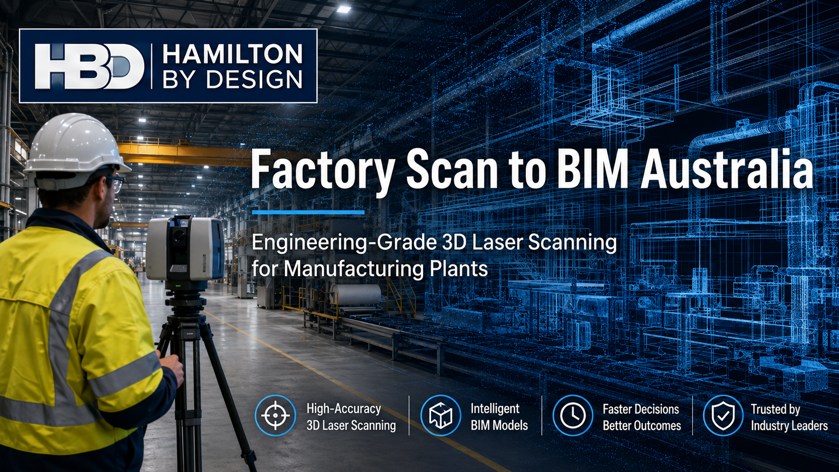
Hamilton By Design provides Factory Scan to BIM services across Australia, using engineering-grade 3D LiDAR laser scanning to capture existing factory conditions and convert them into practical digital information for plant upgrades, equipment installation, engineering design and as-built documentation.
Our approach combines accurate reality capture with engineering, 3D CAD modelling and drafting so the resulting information can be used to solve real brownfield engineering problems.
For broader projects involving buildings, industrial facilities and infrastructure, see our Scan to BIM Australia services.
The Biggest Problem: The Factory Has Changed but the Drawings Have Not
One of the biggest challenges in factory and manufacturing engineering is the reliability of existing information.
A factory may have been operating for 10, 20, 30 or more years.
During that time, individual projects may have changed:
production machinery;
pipework;
ducting;
conveyors;
access platforms;
stairs and handrails;
electrical services;
cable trays;
structural steel;
equipment foundations;
process lines;
storage systems; and
maintenance access.
Unfortunately, those changes are not always incorporated into the original drawings.
The result is a common brownfield engineering problem:
The engineering team may be designing tomorrow’s plant using yesterday’s information.
That creates uncertainty before fabrication and installation begins.
A dimensional error that appears minor on a drawing can become a major problem when new machinery, pipework or structural steel arrives on site and does not fit.
Factory Scan to BIM provides a way to capture the actual existing condition of the facility before the new design is developed.
What Is Factory Scan to BIM?
Factory Scan to BIM is the process of capturing an existing factory using 3D laser scanning and converting the resulting point-cloud information into a digital model suitable for engineering, coordination and documentation.
Hamilton By Design’s 3D Laser Scanning for Engineering Projects service captures millions of spatial measurements across plant, structures, machinery and surrounding interfaces.
These measurements create a detailed point cloud representing the physical factory.
Depending on the project requirements, this information can then be developed into:
BIM models;
3D CAD models;
equipment layouts;
general arrangement drawings;
sections and elevations;
structural geometry;
mechanical layouts;
existing-condition drawings;
clash-review models; and
fabrication or installation reference geometry.
The objective is not simply to create a digital model.
The objective is to give engineers, designers, manufacturers and project teams reliable information about what is actually there.
Why Scan a Factory Before an Upgrade?
Brownfield factory projects are often constrained by existing assets.
Unlike a greenfield development, the new equipment has to work around machinery, structures, services and production systems that are already installed.
Traditional site measurements may capture individual dimensions, but complex industrial environments can contain thousands of interconnected spatial relationships.
3D laser scanning captures the broader environment.
This can help answer practical engineering questions such as:
Will the new machine physically fit?
Is there enough maintenance clearance?
Where is the existing structural steel?
Can new pipework pass through the available space?
Where are existing services located?
Will a new conveyor clash with existing equipment?
Can equipment be fabricated before a shutdown?
What has changed since the original drawings were produced?
Can installation work be planned before arriving on site?
For industrial applications beyond manufacturing facilities, our engineering-grade 3D laser scanning services support mining, heavy industry, infrastructure and brownfield engineering projects across Australia.
Factory Scan to BIM Applications
New Machinery and Equipment Installation
One of the strongest applications for Factory Scan to BIM is preparing for the installation of new machinery.
The surrounding factory can be scanned before detailed design begins.
The captured information can help establish:
available floor area;
ceiling clearances;
surrounding equipment;
column locations;
structural interfaces;
services;
maintenance access;
lifting access;
operator access; and
installation constraints.
The proposed equipment can then be positioned within the captured existing environment before fabrication or installation.
This can significantly improve confidence in fit-up.
Production-Line Modifications
Production lines are frequently modified as factories introduce new products, increase throughput or automate existing processes.
Factory 3D scanning can capture the complete production environment before modifications are designed.
Typical captured assets may include:
conveyors;
production machinery;
guarding;
operator stations;
structural steel;
pipework;
electrical services;
walkways;
access routes; and
surrounding building geometry.
The resulting model provides a reliable basis for evaluating changes to the production line.
Hamilton By Design also provides broader mechanical engineering consulting for industrial machinery, plant upgrades and brownfield modifications.
Brownfield Factory Engineering
Brownfield engineering is fundamentally different from designing a new facility.
The existing factory determines what is possible.
New equipment may need to interface with:
old steelwork;
existing foundations;
legacy machinery;
restricted access;
existing production lines;
pipework;
services;
platforms; and
equipment that cannot easily be relocated.
Factory Scan to BIM provides accurate spatial information before engineering decisions are made.
This allows engineers to design around the real plant rather than assumptions based on incomplete or outdated documentation.
Hamilton By Design’s broader Engineering Services combine reality capture with mechanical design, drafting and brownfield engineering support.
Factory As-Built Surveys
Many factories have incomplete as-built documentation.
Original drawings may exist, but years of modifications can mean they no longer accurately represent the facility.
A factory as-built survey using 3D laser scanning can capture the existing condition and provide a new reference dataset.
This may be particularly useful when:
original drawings cannot be located;
machinery has been relocated;
equipment has been modified;
structural changes were undocumented;
new services have been installed;
several contractors have modified the facility over time; or
future upgrades are being planned.
An accurate digital record can reduce the need to repeatedly return to site for additional measurements.
Reverse Engineering Existing Factory Equipment
Factory scanning does not need to stop at the building or plant layout.
Existing machinery and components can also be captured for reverse engineering.
This can be useful when:
original manufacturing drawings no longer exist;
equipment is obsolete;
replacement parts are unavailable;
machinery has been modified;
components need to interface with legacy equipment; or
new equipment must replicate existing connection geometry.
Hamilton By Design provides Reverse Engineer 3D Scanning for industrial assets where scan data is used as the starting point for engineering interpretation and model development.
Scan to BIM for Factory Pipework and Services
Factories can contain highly congested mechanical and electrical services.
Pipework, ducting, cable trays, conduits and structural elements may all occupy the same restricted areas.
Traditional measurement can become difficult where services overlap or access is limited.
3D laser scanning can capture these relationships from multiple scanner positions and combine them into a coordinated point cloud.
This information can support:
new pipe routes;
ducting modifications;
service relocations;
equipment connections;
clash review;
access planning; and
future plant modifications.
Factory Structural Steel and Equipment Interfaces
Many machinery installations depend upon the geometry of the surrounding structure.
Scanning can capture:
columns;
beams;
bracing;
platforms;
floor levels;
roof structure;
equipment support steel;
openings;
penetrations; and
access structures.
This provides the design team with a digital reference for evaluating how new machinery or structures will interact with the existing factory.
Scan Before the Shutdown
Factory shutdowns are expensive and often tightly scheduled.
Where practical, laser scanning can be completed before the shutdown so engineering and modelling can progress while the factory continues operating.
This can allow:
Site scanning → point-cloud registration → 3D modelling → engineering → fabrication planning → shutdown installation
rather than beginning measurement and engineering after the plant is already offline.
This is particularly valuable where shutdown duration needs to be minimised.
Hamilton By Design’s industrial scanning experience includes plant, equipment, structures and materials-handling systems where accurate existing-condition information is required for engineering and shutdown work.
What Can Be Captured During a Factory Scan?
A Factory Scan to BIM project can capture a combination of:
Machinery and Production Equipment
production machinery;
processing equipment;
packaging equipment;
pumps;
motors;
gearboxes;
tanks;
vessels;
hoppers; and
specialised machinery.
Materials Handling
conveyors;
transfer points;
chutes;
rollers;
support structures;
guarding; and
loading systems.
Mechanical Services
pipework;
valves;
ducting;
pumps;
compressed-air lines;
utility services; and
equipment connections.
Structures
structural steel;
columns;
beams;
platforms;
stairs;
handrails;
roof structures; and
equipment support frames.
Building Geometry
floors;
walls;
ceilings;
doors;
openings;
penetrations;
plant rooms; and
access routes.
From Point Cloud to Engineering Model
The registered point cloud is only the starting point.
Hamilton By Design can use captured scan data to support subsequent engineering and drafting.
A typical workflow may include:
Factory Survey
↓
3D LiDAR Laser Scanning
↓
Point-Cloud Registration
↓
Existing-Condition Review
↓
3D CAD / BIM Development
↓
Engineering Design
↓
Drawings and Documentation
↓
Fabrication and Installation
Where conventional engineering documentation is required, our Mechanical Drafting Australia service supports plant upgrades, fabrication, maintenance and brownfield modification projects across Australia.
Factory Scan to BIM Deliverables
Deliverables can be tailored to the project and may include:
registered point clouds;
E57 files;
RCP/RCS datasets;
LAS point clouds;
BIM models;
IFC models;
SolidWorks models;
STEP files;
SAT files;
AutoCAD DWG drawings;
DXF files;
general arrangement drawings;
sections;
elevations;
equipment layouts;
existing-condition plans;
interface models; and
engineering documentation.
The appropriate deliverable depends on what the model needs to achieve.
A project intended to establish general factory geometry may require a different level of modelling from a project involving detailed equipment interfaces.
Engineer-Led Factory 3D Scanning
There is an important distinction between scanning a factory and understanding what needs to be captured for an engineering project.
Hamilton By Design approaches factory scanning from an engineering perspective.
Before scanning begins, consideration can be given to questions such as:
What equipment is being replaced?
Which interfaces are critical?
What level of accuracy is required?
Which areas need detailed capture?
What information will the designers require?
What format does the final engineering team need?
Is fabrication expected before installation?
Are future plant modifications likely?
This allows the scanning strategy to be developed around the actual engineering requirement.
Factory Scan to BIM Across Australia
Hamilton By Design provides Factory Scan to BIM and industrial 3D scanning services across Australia.
Project locations can include:
Sydney
Newcastle
Central Coast NSW
Wollongong
Brisbane
Melbourne
Adelaide
Perth
Darwin
Regional NSW
Regional Queensland
Regional Victoria
Regional Western Australia
and remote industrial locations.
Our broader 3D Laser Scanning service supports projects throughout Australia, including major metropolitan centres and regional industrial locations.
Industries That Can Benefit from Factory Scan to BIM
Factory Scan to BIM can support many manufacturing and processing sectors, including:
food and beverage manufacturing;
packaging;
pharmaceutical manufacturing;
chemical processing;
heavy manufacturing;
steel processing;
mining equipment manufacturing;
automotive manufacturing;
timber processing;
building products;
plastics;
recycling;
water treatment equipment;
warehousing and logistics;
materials handling; and
general industrial manufacturing.
The technology is particularly valuable where a new project needs to integrate with an existing operating facility.
Why Use Factory Scan to BIM?
Factory Scan to BIM can help reduce uncertainty at the beginning of a project.
Potential advantages include:
better existing-condition information;
fewer assumptions during design;
reduced requirement for repeated site measurement;
earlier identification of spatial constraints;
improved equipment fit-up;
better coordination between engineering disciplines;
improved ability to design remotely;
more confidence before fabrication;
improved shutdown preparation; and
better long-term asset documentation.
The value is not simply in creating a BIM model.
The real value is having better information before expensive engineering, fabrication and installation decisions are made.
Factory Scan to BIM Australia — Frequently Asked Questions
What is Factory Scan to BIM?
Factory Scan to BIM uses 3D laser scanning to capture an existing manufacturing facility and convert that information into BIM, CAD or engineering models representing the actual installed conditions.
Can you scan an operating factory?
Yes. Many factory scans can be completed while facilities remain operational, subject to site access, safety requirements and the type of equipment being captured.
Can factory machinery be included in the BIM model?
Yes. Machinery, conveyors, pipework, services, structural steel and surrounding building geometry can all be captured where required.
Can you scan a factory when the drawings are outdated?
Yes. This is one of the strongest applications for factory scanning. The scan captures existing conditions rather than relying entirely on legacy drawings.
Can the scan be used for SolidWorks design?
Yes. Point-cloud information can be used as reference data for SolidWorks and other CAD modelling workflows where the appropriate geometry is developed from the scan.
Can Factory Scan to BIM help with equipment installation?
Yes. Existing factory geometry can be compared with proposed equipment before installation to identify clearances, interfaces and potential clashes.
Do you provide Factory Scan to BIM outside Sydney?
Yes. Hamilton By Design supports 3D laser scanning and engineering projects across Australia.
Planning a Factory Upgrade?
If you are preparing to install new equipment, modify a production line, upgrade existing machinery or undertake a brownfield factory project, accurate existing-condition information can significantly improve the starting point for engineering.
Hamilton By Design provides Factory Scan to BIM, 3D laser scanning, mechanical engineering, reverse engineering and drafting services across Australia.
Instead of designing around drawings that may no longer represent the facility, capture the factory as it exists today.
Scan the existing plant. Understand the interfaces. Design around reality.
Related Factory Scan to BIM, 3D Scanning & Engineering Services
Explore additional Hamilton By Design services supporting factory upgrades,
manufacturing facilities, brownfield engineering, 3D laser scanning,
point-cloud modelling and engineering documentation across Australia.
Engineering Design and Drafting for Industrial, Mining and Infrastructure Projects
Successful engineering projects depend on more than a good idea. They require accurate information, practical design decisions and clear technical documentation that can be understood by engineers, fabricators, contractors, installers and asset owners.
Engineering design and drafting connect the initial project requirement with the final manufactured or installed result. They transform site information, calculations, concepts and operational requirements into coordinated 3D models and technical drawings.
The objective is not simply to produce drawings. It is to create practical engineering information that supports decision-making, procurement, fabrication, construction, installation, operation and future maintenance.
What Is Engineering Design and Drafting?
Engineering design is the process of developing a practical solution to a technical problem. It considers how an asset should function, how it will be manufactured or constructed, how it interfaces with existing equipment and how it can be safely operated and maintained.
Engineering drafting communicates that solution through accurate models and drawings.
Depending on the project, engineering drafting deliverables may include:
three-dimensional CAD models
general arrangement drawings
manufacturing drawings
structural steel layouts
fabrication and workshop drawings
assembly and exploded views
pipework layouts and isometrics
equipment arrangement drawings
installation details
bills of materials
sections, elevations and details
as-built documentation
redline drawing updates
The design and drafting stages should work together. A technically sound concept must be converted into documentation that is clear, coordinated and suitable for its intended use.
Hamilton By Design’s broader mechanical engineering services connect engineering analysis, site investigation, CAD modelling and drafting within a coordinated project workflow.
Why Engineering-Led Drafting Matters
Drafting software can create accurate lines and geometry, but software alone does not determine whether a design is practical.
Engineering-led drafting considers the real conditions that affect fabrication and installation, including:
available materials and standard sections
welding and machining requirements
practical tolerances
equipment loads
access for assembly and maintenance
lifting and installation constraints
clearances around existing plant
interfaces with structural, mechanical and civil systems
relevant Australian Standards
the sequence in which components will be manufactured and installed
A drawing may appear complete while still containing unresolved engineering issues. For example, a platform may fit within the available space but restrict maintenance access. A pipe route may avoid one structural member while conflicting with another service. A fabricated frame may be dimensionally correct but impossible to lift into position as a complete assembly.
Combining engineering knowledge with professional mechanical and structural drafting helps identify these issues before they reach the workshop or site.
Mechanical Design and Drafting
Mechanical design and drafting are used to develop machinery, plant equipment and supporting systems.
Typical applications include:
conveyors and transfer stations
chutes and hoppers
mechanical guards
pump and motor arrangements
tanks and process equipment
equipment support frames
pipework and ducting
lifting and handling equipment
maintenance platforms
replacement components
machine modifications
industrial equipment layouts
The process may begin with an existing concept, a site problem, a marked-up drawing, a physical component or a functional requirement.
A mechanical design can then be developed progressively through concept layouts, review models, detailed assemblies and fabrication drawings. This incremental approach allows assumptions to be checked and important interfaces to be confirmed before unnecessary detailing is completed.
Structural and Fabrication Drafting
Industrial projects frequently require new structural steel to support equipment, improve access or accommodate plant modifications.
Structural and fabrication drafting may include:
platforms and walkways
stairs, ladders and handrails
equipment support structures
conveyor support frames
maintenance access systems
structural modifications
connection details
base plates and brackets
lifting frames
workshop drawing packages
Fabrication drawings need to communicate more than overall dimensions. They may also need to identify materials, weld requirements, hole positions, fasteners, surface treatments, part numbers and assembly relationships.
Clear documentation reduces uncertainty in the workshop and allows questions to be addressed before fabrication begins.
Using 3D Laser Scanning to Improve Design Accuracy
Brownfield and retrofit projects often begin with incomplete or outdated information.
Original drawings may no longer represent the installed plant. Equipment may have been moved, structural steel modified, pipework rerouted or access systems added over many years.
Manual measurements can capture selected dimensions, but they may not provide enough information to understand a congested three-dimensional environment.
Engineering-grade 3D laser scanning captures millions of measured points across visible plant, equipment and structures. These points form a registered point cloud representing existing site conditions.
The point cloud can support:
existing-condition verification
equipment positioning
clash detection
access and clearance reviews
pipework routing
structural modification planning
installation sequencing
fabrication interface checks
as-built documentation
reverse engineering
Scanning is particularly valuable where site access is limited, shutdown periods are short or fabrication errors would be costly.
From Point Cloud to Engineering Model
A point cloud is a detailed spatial record, but it is not automatically an engineering model.
The dataset must be reviewed in relation to the project objective. Critical equipment, structures and interfaces can then be converted into practical CAD geometry.
Hamilton By Design provides point-cloud-to-AutoCAD services for projects requiring 2D plans, sections, elevations, layouts and engineering drawings developed from scanned site conditions.
Depending on the project, point-cloud information may be used to produce:
simplified equipment envelopes
structural steel models
mechanical assemblies
plant layouts
installation interfaces
existing pipework routes
general arrangement drawings
proposed-design overlays
fabrication geometry
Not every visible object needs to be modelled. The appropriate level of detail depends on how the information will be used.
Modelling only the important project interfaces can reduce processing time while preserving the information needed for engineering decisions.
SolidWorks Design and Drafting
Three-dimensional parametric modelling allows equipment, parts and assemblies to be developed in a coordinated digital environment.
exporting neutral CAD formats for other project participants
Three-dimensional models also allow clients, fabricators and site teams to review a proposal before fabrication begins. This can make design discussions clearer than relying only on conventional two-dimensional drawings.
Engineering Design for Brownfield Projects
Brownfield projects involve modifying or adding to an existing facility.
They can be more complex than greenfield projects because the new design must fit around installed structures, operating equipment and established services.
Typical brownfield constraints include:
restricted installation space
unknown or undocumented geometry
limited site access
existing assets that must remain operational
short shutdown windows
multiple design interfaces
legacy equipment and drawings
restricted lifting and transport routes
A practical brownfield workflow may involve site inspection, laser scanning, point-cloud registration, CAD modelling, engineering review and staged drawing development.
The design team can first confirm the existing conditions and major interfaces. The proposed design can then be developed around reliable site data rather than assumptions.
Supporting Fabrication and Installation
Engineering design and drafting should make the next stage of the project easier.
Fabricators need clear information about what must be manufactured. Installers need to understand where components are located and how they connect to the existing plant. Project managers need confidence that interfaces have been reviewed.
Useful drawing packages may include:
drawing registers
general arrangement drawings
detailed part drawings
welded assembly drawings
installation layouts
material specifications
bills of materials
revision records
notes identifying site verification requirements
Where dimensions cannot be confirmed, assumptions and hold points should be clearly identified rather than hidden within the model.
This provides a more transparent basis for project decisions and helps prevent unverified information from being treated as confirmed site data.
Local and Australia-Wide Drafting Support
Hamilton By Design is based on the NSW Central Coast and supports projects throughout Australia.
Clients requiring local assistance can learn more about engineering drafting services on the Central Coast, including mechanical drafting, fabrication drawings, legacy drawing updates and as-built documentation.
Services can be provided for individual components, plant modifications, ongoing project support or larger engineering packages.
Frequently Asked Questions
What information is needed to begin an engineering drafting project?
Useful starting information may include sketches, photographs, existing drawings, dimensions, equipment data, design calculations, site constraints and the intended use of the final drawings. Where reliable site information is unavailable, a site inspection or 3D laser scan may be recommended.
Can drawings be produced from an existing physical component?
Yes. Existing components can be measured manually or captured using 3D scanning, depending on their size, complexity and required accuracy. The information can then be used to develop a reverse-engineered CAD model and manufacturing drawings.
What is the difference between a 3D model and a fabrication drawing?
A 3D model represents the geometry and relationships between components. A fabrication drawing communicates the dimensions, materials, tolerances, welds, finishes and other information required to manufacture the component. A model alone may not contain everything a fabricator needs.
Can old drawings be updated?
Yes. Legacy paper drawings, PDFs, marked-up prints and older CAD files can be reviewed and converted into updated digital drawings. Site verification may be required where the existing asset has been modified since the original drawings were issued.
Can point clouds be used directly for design?
Yes. Point clouds can be referenced in CAD software to measure existing conditions, position proposed equipment and check clearances. Selected geometry can also be converted into structured CAD models where required.
Do all objects in a scan need to be modelled?
No. The modelling scope should reflect the engineering objective. Modelling only the relevant equipment, structures and interfaces is often more efficient than creating a highly detailed model of the entire facility.
What drawing formats can be supplied?
Typical deliverables may include PDF, DWG and DXF drawings, together with SolidWorks, STEP, SAT or Parasolid models. Point-cloud formats may include E57, RCP, RCS and LAS, depending on the project requirements.
Can Hamilton By Design support both design and site capture?
Yes. Hamilton By Design combines site measurement, 3D LiDAR scanning, engineering design, CAD modelling and drafting. This creates a coordinated workflow from existing-condition capture through to engineering documentation.
Additional answers about scanning, modelling and engineering deliverables are available in the Hamilton By Design frequently asked questions.
Discuss Your Engineering Design and Drafting Project
Accurate engineering design and drafting create a reliable connection between an initial requirement and the final fabricated or installed asset.
By combining practical engineering experience, 3D CAD modelling, LiDAR scanning and clear technical documentation, Hamilton By Design helps clients reduce uncertainty, coordinate project interfaces and develop information that can be used confidently by fabricators, contractors and site teams.
Whether the requirement involves a single replacement component, a mechanical assembly, structural steel, a plant upgrade or a complete brownfield documentation package, the process should begin by defining the project objective, critical interfaces and required deliverables.
Hamilton By Design Co. Mechanical Engineering | 3D Laser Scanning | 3D Modelling Australia-wide engineering and project support
Explore additional Hamilton By Design services covering
engineering-led design, mechanical and structural drafting,
3D CAD modelling, fabrication documentation and accurate
existing-condition capture.
Australian Design and Drafting Services
Engineering design and drafting for mining, industrial,
manufacturing and infrastructure projects across Australia.
Scan to BIM Perth WA | LiDAR Scanning & BIM Modelling
Embracing the idea of Scan to BIM Perth WA would suggest accurate site information is critical for successful engineering, construction, maintenance and upgrade projects. In Perth and across Western Australia, many mining, industrial, commercial and infrastructure assets have changed over time, but the drawings have not always kept up.
Equipment gets replaced. Pipework is modified. Structural steel is strengthened or repaired. Access platforms are changed. Services are rerouted. Buildings are refurbished. Over time, the original drawings may no longer reflect what is actually installed on site.
This is where Scan to BIM Perth becomes valuable.
Scan to BIM is the process of capturing an existing site using 3D laser scanning or LiDAR technology, then converting that point cloud data into an accurate Building Information Model. The result is a usable digital model that helps engineers, project managers, builders, asset owners and maintenance teams make better decisions based on real site conditions.
Hamilton By Design provides engineering-led Scan to BIM services across Perth and Western Australia, supporting mining, industrial, commercial, infrastructure and brownfield upgrade projects.
For projects that require accurate reality capture before design or fabrication begins, Hamilton By Design also provides 3D laser scanning in Perth to capture reliable point cloud data for downstream BIM, CAD and engineering workflows.
The Biggest Problem: Inaccurate or Missing As-Built Information
The biggest problem Scan to BIM solves is the lack of reliable as-built information.
Many Perth and WA sites rely on old drawings, incomplete records or assumptions made from previous projects. In some cases, drawings may exist but do not include later site modifications. In other cases, asset owners may only have PDFs, hand-marked drawings or partial CAD files.
This creates major project risk.
If engineers are designing from inaccurate information, new equipment may not fit. Steelwork may clash with existing structure. Pipe routes may conflict with services. Fabricated parts may arrive on site and require modification. Shutdown work may take longer than planned because the real site does not match the design assumptions.
These issues can lead to:
Design clashes
Fabrication errors
Installation delays
Extra site visits
Shutdown overruns
Safety risks
Increased project costs
Poor coordination between trades
Rework during construction
Poor asset records for future maintenance
For brownfield industrial and mining projects, these risks are especially important because work is often carried out around live plant, restricted access zones, shutdown windows and complex existing infrastructure.
Scan to BIM helps reduce this uncertainty by capturing the actual site and turning it into practical digital information.
What Is Scan to BIM?
Scan to BIM combines two key processes: reality capture and Building Information Modelling.
First, the existing site is captured using 3D laser scanning or LiDAR. The scanner records millions of measurement points across the site. These points form a point cloud, which is a highly accurate 3D representation of the existing conditions.
The point cloud can then be used to create a BIM model. Depending on the project, this model may include building elements, structural steel, pipework, mechanical equipment, platforms, conveyors, access systems, services, walls, slabs, columns and other site features.
The final model may be delivered in formats such as Revit, Navisworks, IFC, DWG or other agreed digital formats.
The key value is that the model is based on measured site data, not guesswork.
Who Uses Scan to BIM in Perth?
Scan to BIM is used by a wide range of organisations and project teams across Perth and Western Australia.
Typical users include:
Mining companies
Industrial plant owners
Commercial property owners
Infrastructure operators
Engineering consultants
Mechanical engineers
Structural engineers
Architects
Builders
Fabricators
Shutdown planners
Asset managers
Maintenance teams
Project managers
Facility managers
For asset owners, Scan to BIM provides better records of what is installed.
For engineers, it provides a more reliable base for design.
For builders and fabricators, it helps reduce clashes and installation problems.
For maintenance teams, it supports planning, access review and future asset management.
Where Is Scan to BIM Used in Perth and WA?
Scan to BIM can be used anywhere existing conditions need to be captured accurately.
In Perth, this may include commercial buildings, hospitals, schools, industrial workshops, warehouses, manufacturing sites, processing plants, water infrastructure, ports and transport facilities.
Across Western Australia, Scan to BIM is also valuable for mining and heavy industrial locations, including processing plants, materials handling facilities, port infrastructure, power generation assets, pump stations, treatment plants and regional industrial sites.
Common WA locations and project areas include:
Perth CBD
Kwinana
Henderson
Welshpool
Canning Vale
Fremantle
Rockingham
Bunbury
Geraldton
Kalgoorlie
Port Hedland
Karratha
Pilbara
Goldfields
Regional Western Australia
Hamilton By Design supports broader engineering and scanning work through its Perth WA engineering and 3D scanning services page, which is a useful internal location hub for Perth-based clients.
How the Scan to BIM Process Works
A typical Scan to BIM workflow includes several stages.
1. Project Scope and Capture Planning
Before scanning begins, the project team needs to understand what the model will be used for.
This is important because not every Scan to BIM project needs the same level of detail. A model for architectural refurbishment may require different information compared with a model for conveyor upgrades, pipework modifications, structural access design or plant layout changes.
Key questions include:
What area needs to be captured?
What level of detail is required?
Is the model for design, construction, asset records or maintenance?
Are mechanical and structural elements required?
Are services and pipework required?
What deliverable format is needed?
Is the work being used for clash detection?
Is the site live, restricted or difficult to access?
Clear scope at the start helps ensure the final model is useful.
2. 3D Laser Scanning or LiDAR Site Capture
The site is captured using professional 3D scanning equipment. The scanner collects accurate spatial data from multiple positions around the site.
For complex industrial facilities, multiple scan positions may be required to capture equipment, steelwork, pipework, access platforms, conveyors and building elements from different angles.
The result is a point cloud that represents the real site geometry.
3. Point Cloud Registration
After site capture, the individual scans are registered together into a single coordinated point cloud.
This stage aligns the scans so the full site can be reviewed as one digital environment.
Typical point cloud formats may include:
E57
RCP
RCS
LAS
The registered point cloud becomes the foundation for the BIM model.
4. BIM Model Development
The point cloud is then used to create a BIM model. Depending on the project, this may include modelling architectural, structural, mechanical or services elements.
For industrial and mining projects, modelled items may include:
Structural steel
Platforms
Stairs
Handrails
Pipework
Tanks
Pumps
Conveyors
Chutes
Hoppers
Mechanical equipment
Access areas
Building structure
Services corridors
The goal is not just to make the model look good. The goal is to create a model that supports real project decisions.
Where CAD deliverables are required rather than a full BIM workflow, Hamilton By Design can also convert point cloud data into engineering models and drawings through its Scan to CAD Perth service.
5. Quality Review Against the Point Cloud
Once the BIM model is created, it should be checked against the point cloud. This helps confirm that the model reflects the captured site conditions and that the required scope has been covered.
Quality review is important because Scan to BIM is only useful if the model is accurate enough for the intended purpose.
A model used for general planning may not require the same detail as a model used for fabrication coordination, clash detection or construction sequencing. The required accuracy and level of detail should match the project outcome.
6. Delivery of BIM and CAD Outputs
Final deliverables depend on the project requirements.
Scan to BIM relies on a combination of capture equipment, point cloud software, BIM software and engineering review.
Useful tools include:
Tool
Purpose
3D laser scanner / LiDAR
Captures accurate site geometry
FARO Focus / terrestrial scanner
Engineering-grade site capture
FARO SCENE
Point cloud registration and processing
Autodesk ReCap
Point cloud preparation for Autodesk workflows
Revit
BIM model development
Navisworks
Coordination and clash review
AutoCAD
2D drawings and CAD outputs
IFC
Model exchange between software platforms
E57 / RCP / RCS / LAS
Point cloud delivery formats
SolidWorks / Inventor
Mechanical modelling where required
The right tools depend on the final use of the data. A commercial building project may require a Revit-focused workflow, while an industrial plant upgrade may need a combination of point cloud, CAD, BIM and mechanical modelling outputs.
Why Engineering-Led Scan to BIM Matters
Not all Scan to BIM providers approach the work the same way.
Some providers focus mainly on scanning and visual modelling. That may be enough for some building documentation projects, but industrial and mining sites often need a deeper understanding of how the asset works.
Engineering-led Scan to BIM is different because the model is developed with practical project outcomes in mind.
For example, in a processing plant, the important question may not simply be “what does the site look like?” The real questions may be:
Will the new equipment fit?
Can the conveyor be modified safely?
Is there enough access for installation?
Will new pipework clash with existing steel?
Can the platform support maintenance access?
What needs to be removed before shutdown?
Can fabrication drawings be developed from the scan data?
What existing structure must remain untouched?
Hamilton By Design’s Scan to BIM approach is suited to mechanical, structural, mining and industrial environments where the digital model needs to support real engineering decisions.
For clients working nationally, the broader Scan to BIM Mining and Industrial Facilities page provides additional context around mining, processing plant, materials handling and heavy industrial applications.
Benefits of Scan to BIM Perth
Scan to BIM provides several important benefits for Perth and WA projects.
Better Design Accuracy
Design teams can work from real site data instead of old drawings or assumptions. This reduces the risk of designing around information that no longer reflects the site.
Reduced Site Rework
Accurate existing-condition data helps reduce fabrication and installation problems. This is particularly valuable where fabricated components need to fit into existing plant, structure or services.
Improved Clash Detection
Models can be reviewed before construction to identify conflicts between new and existing elements.
This helps project teams detect problems before labour, materials and equipment are committed to site work.
Faster Project Planning
Teams can review the site digitally without always needing to return to site.
This is useful for remote WA projects where travel, access and site inductions can add time and cost.
Improved Shutdown Confidence
For mining and industrial projects, accurate scan data helps plan work before shutdown begins.
Shutdowns are often expensive and time-sensitive. Scan to BIM helps reduce uncertainty before work starts.
Better Asset Records
Owners receive a more reliable digital record of existing assets.
This can support future maintenance, inspections, upgrades and long-term asset management.
Improved Collaboration
BIM models provide a shared reference point for engineers, builders, contractors, fabricators and asset managers.
When everyone is working from the same accurate information, coordination improves.
Scan to BIM for Brownfield Projects
Brownfield projects are one of the strongest use cases for Scan to BIM.
Unlike greenfield projects, brownfield sites already contain existing plant, structure, services, access restrictions and operational constraints. The site may have been modified many times over decades.
This makes accurate information critical.
Scan to BIM helps brownfield projects by capturing the real conditions before design or fabrication begins. This reduces the chance of clashes, improves planning and gives project teams a more reliable foundation for decision-making.
For Perth and WA mining, resources, port and industrial projects, this can be the difference between a smooth installation and a costly shutdown delay.
Recommended Page Details
SEO Item
Suggested Detail
Page Name
Scan to BIM Perth WA
URL
/scan-to-bim-perth/
Keyword Focus
Scan to BIM Perth
Location
Perth WA
Meta Description
Engineering-led Scan to BIM services in Perth WA. Convert 3D laser scan data into accurate BIM models for mining, industrial, commercial, infrastructure and brownfield upgrade projects.
FAQs
What is Scan to BIM?
Scan to BIM is the process of capturing an existing site using 3D laser scanning or LiDAR, then converting the point cloud data into a Building Information Model. The model can be used for design, construction planning, asset management, clash detection and future maintenance.
Why is Scan to BIM useful for Perth and WA projects?
Scan to BIM is useful because many Perth and WA assets have incomplete or outdated drawings. By capturing the real site conditions, project teams can reduce assumptions, avoid clashes and plan upgrades with greater confidence.
What industries use Scan to BIM in Perth?
Scan to BIM is used across mining, mineral processing, ports, manufacturing, commercial buildings, infrastructure, water treatment, power generation and industrial facilities.
What deliverables can be provided from a Scan to BIM project?
Typical deliverables may include Revit models, Navisworks models, IFC files, DWG drawings, 2D plans, sections, elevations, registered point clouds, E57 files, RCP files, RCS files and PDF documentation.
Is Scan to BIM only for buildings?
No. Scan to BIM can be used for buildings, but it is also valuable for industrial plants, mining infrastructure, processing facilities, pipework, structural steel, conveyors, platforms, equipment and brownfield engineering projects.
Can Scan to BIM help reduce shutdown risk?
Yes. Scan to BIM can help project teams understand existing site conditions before shutdown work begins. This can reduce clashes, improve sequencing and reduce the risk of unexpected site issues during installation.
What is the difference between Scan to BIM and Scan to CAD?
Scan to BIM usually creates an information-rich model, often used in Revit, Navisworks or IFC workflows. Scan to CAD usually focuses on producing CAD models and drawings for engineering, drafting, fabrication or layout work. The right choice depends on the project outcome.
Do I need a full BIM model for every project?
No. Some projects only need a point cloud, 2D drawings or a Scan to CAD model. Other projects need a full BIM model for coordination, asset management or construction planning. The deliverable should match the project need.
Scan to BIM Perth gives project teams a more reliable way to understand existing buildings, plants and infrastructure before design, fabrication or construction begins.
For Perth and Western Australia, where mining, industrial, commercial and infrastructure assets often involve complex existing conditions, accurate digital information can reduce risk, improve coordination and support better long-term asset management.
By combining 3D laser scanning, point cloud processing, BIM modelling and engineering experience, Hamilton By Design helps turn real site conditions into practical digital deliverables that support better project outcomes.
To provide the best experiences, we use technologies like cookies to store and/or access device information. Consenting to these technologies will allow us to process data such as browsing behaviour or unique IDs on this site. Not consenting or withdrawing consent, may adversely affect certain features and functions.
Functional
Always active
The technical storage or access is strictly necessary for the legitimate purpose of enabling the use of a specific service explicitly requested by the subscriber or user, or for the sole purpose of carrying out the transmission of a communication over an electronic communications network.
Preferences
The technical storage or access is necessary for the legitimate purpose of storing preferences that are not requested by the subscriber or user.
Statistics
The technical storage or access that is used exclusively for statistical purposes.The technical storage or access that is used exclusively for anonymous statistical purposes. Without a subpoena, voluntary compliance on the part of your Internet Service Provider, or additional records from a third party, information stored or retrieved for this purpose alone cannot usually be used to identify you.
Marketing
The technical storage or access is required to create user profiles to send advertising, or to track the user on a website or across several websites for similar marketing purposes.