If you’re searching for SolidWorks Perth, you’re likely looking for reliable SolidWorks drafting support that produces drawings and models that fabricate and install correctly — not just CAD files that look good on screen.
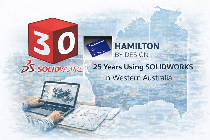
Hamilton By Design provides engineer-led SolidWorks drafting services in Perth, supporting WA fabricators, contractors, and industrial operators with fabrication-ready documentation and practical engineering judgement.
Engineer-Led SolidWorks Drafting Support for Perth & WA Projects
Perth projects often involve brownfield assets, tight access, and programmes where mistakes turn into rework, delays, and cost. The biggest risk isn’t “can we model it?” — it’s whether the drawings reflect:
- Site reality
- Fabrication constraints
- Tolerances and interfaces
- Installation sequencing and access
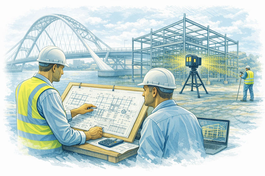
That’s why our SolidWorks drafting is engineering-led.
Who Engages SolidWorks Drafting Services in Perth
Perth clients commonly engage us when they need to:
- Outsource SolidWorks drafting with engineering oversight
- Update or recreate drawings that no longer match existing plant
- Add drafting capacity during tenders, shutdowns, or project spikes
- Produce workshop drawings that fabricators can build from
- Reduce fit-up risk on modifications and upgrades
Many enquiries start as “hire a SolidWorks drafter Perth” — but our service is built for clients who also want engineering judgement behind every drawing.
SolidWorks Drafting Services We Provide in Perth
Our Perth SolidWorks drafting support includes:
- Mechanical part and assembly drafting
- Fabrication-ready workshop drawings
- Structural and support steel detailing (where applicable)
- Upgrade and modification drawing packages
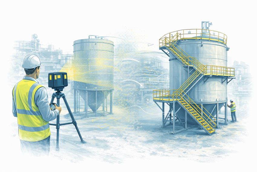
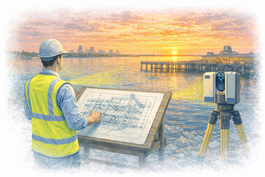
- Reverse-engineered part drawings (from site data)
- As-built documentation and drawing updates
- CAD outputs suitable for fabrication workflows and project handover
All deliverables are created with fabrication and installation readiness in mind — not just CAD accuracy.
Why Engineering-Led Drafting Matters
SolidWorks is a powerful platform, but CAD alone does not prevent project failure.
Engineering-led drafting helps Perth teams by:
- Reducing tolerance and interface clashes before fabrication
- Producing drawings that are clear and buildable under real constraints
- Supporting tender-stage decisions with accurate documentation
- Minimising rework and improving shutdown certainty
This approach is particularly valuable on brownfield and shutdown-critical works in WA.

Need Extra Drafting Capacity? Secondment Available
If your Perth team needs extra drafting capacity integrated into your workflow, we also offer engineering-led secondment services.
Learn more about Secondment Services
Secondment is ideal for:
- Fabricators scaling up for tenders
- Project teams during peak design / drafting loads
- Shutdown and brownfield upgrade packages requiring close coordination
Industries We Commonly Support Around Perth
We support SolidWorks drafting and engineering documentation for:
- Mining services and resources contractors
- Oil & gas / energy infrastructure
- Fabrication and structural steel workshops
- Ports, logistics, and bulk handling facilities
- Manufacturing and industrial maintenance teams
Whether you’re in Perth metro, Kwinana, Henderson, or supporting regional WA operations, we can deliver drafting support with clear scope and disciplined outputs.
Our clients:


How We Differ From Drafting-Only Providers
Many drafting vendors deliver CAD files but do not own fit-up risk.
Hamilton By Design provides:
- Engineering ownership, not drafting in isolation
- Fabrication-aware drawings aligned to real build constraints
- Better interface clarity and reduced interpretation risk
- Accountable outputs suited to procurement, fabrication, and installation
This is drafting designed to perform on site.


Speak With an Engineer About SolidWorks Drafting in Perth
If you’re looking for SolidWorks drafting support in Perth — whether as a defined drafting package or embedded secondment — let’s talk early and reduce risk before fabrication begins.
Use the contact form below to discuss your Perth SolidWorks drafting requirements.