Industrial platforms are commonly viewed as supporting structures that simply provide access to equipment and operating areas. In many projects the design process focuses heavily on meeting minimum standards and compliance requirements.
While compliance is essential, successful platform design extends beyond satisfying engineering checklists.
Mining and processing facilities rely on platforms every day for:
- Maintenance activities
- Equipment inspections
- Shutdown work
- Operational access
- Plant monitoring
- Emergency access
- Equipment removal and installation
Poor platform design can create safety concerns, maintenance challenges, and operational inefficiencies that remain throughout the life of the asset.
At Hamilton By Design, we view platform design as an engineering solution supporting productivity, maintenance, and long-term operational performance rather than simply meeting minimum requirements.
Why Industrial Platform Design Matters
Platforms directly affect how personnel interact with equipment and infrastructure.
Well-designed systems can improve:
- Worker safety
- Maintenance access
- Equipment accessibility
- Shutdown performance
- Plant productivity
- Long-term operating costs
Poor platform layouts may create:
- Congested access areas
- Restricted maintenance access
- Increased manual handling risks
- Difficult equipment removal
- Longer shutdown durations
- Increased project costs
Platform design influences how effectively a facility operates every day.
Compliance is the Starting Point
Mining and processing facilities frequently consider standards including:
- AS1657 – Fixed Platforms, Walkways, Stairways and Ladders
- AS3996 – Access Covers and Grates
- Structural loading requirements
- Site-specific engineering requirements
Standards establish minimum requirements for:
- Platform dimensions
- Walkway widths
- Guardrails
- Handrails
- Stair geometry
- Ladder systems
- Access openings
Compliance is important, but meeting minimum requirements alone does not guarantee an efficient design.


Maintenance Access Often Drives Better Outcomes
Maintenance teams commonly interact with platforms more frequently than operations personnel.
Platform design should consider:
- Equipment removal paths
- Tool access requirements
- Safe working zones
- Inspection locations
- Clearance requirements
- Shutdown activities
- Future maintenance needs
Questions often worth asking include:
- Can pumps or motors be removed safely?
- Can maintenance teams work comfortably?
- Is lifting equipment accessible?
- Can personnel safely carry tools and equipment?
- Is there room for future upgrades?
Designing around maintenance activities often improves long-term outcomes.
Human Factors Matter
Platform systems should be designed around how people actually move and work.
Human considerations can include:
- Visibility
- Reach distances
- Working posture
- Congestion
- Manual handling requirements
- Access frequency
- Emergency escape routes
Designs that ignore human interaction can create unnecessary operational difficulties.
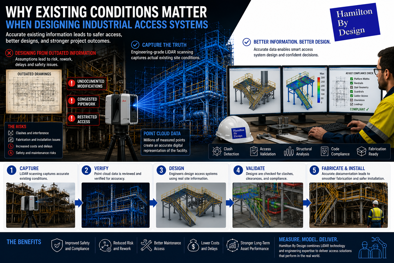
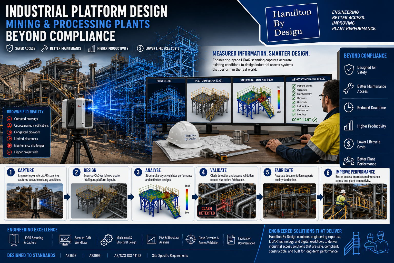
Brownfield Environments Create Additional Challenges
Most mining and processing facilities are not greenfield sites.
Brownfield facilities commonly include:
- Existing structural steel
- Pipework congestion
- Historical modifications
- Equipment additions
- Limited clearances
- Legacy infrastructure
Existing drawings may no longer represent current operating conditions.
Designing new platforms around assumptions can increase:
- Fabrication risk
- Site rework
- Installation delays
- Shutdown costs
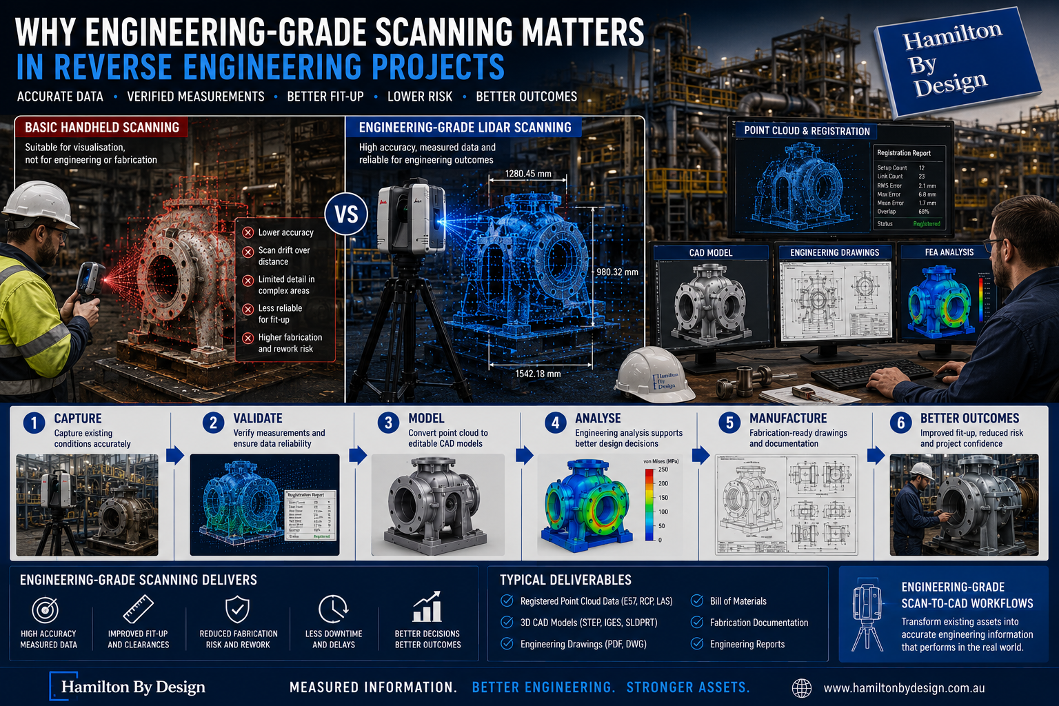
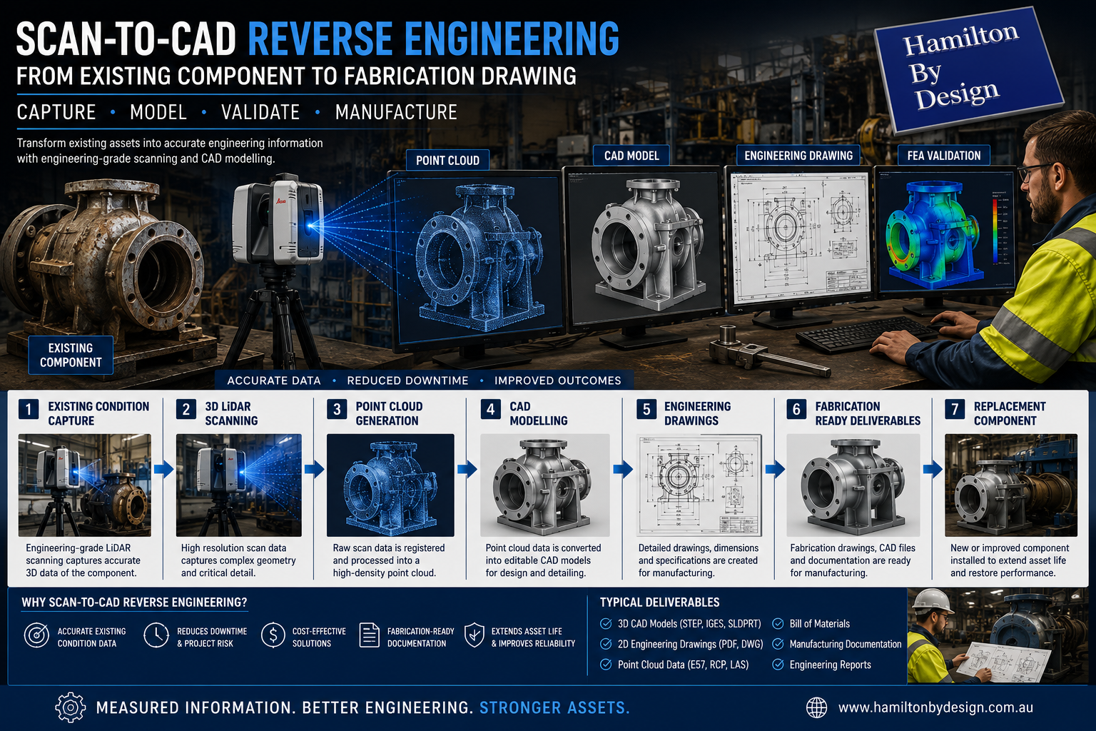
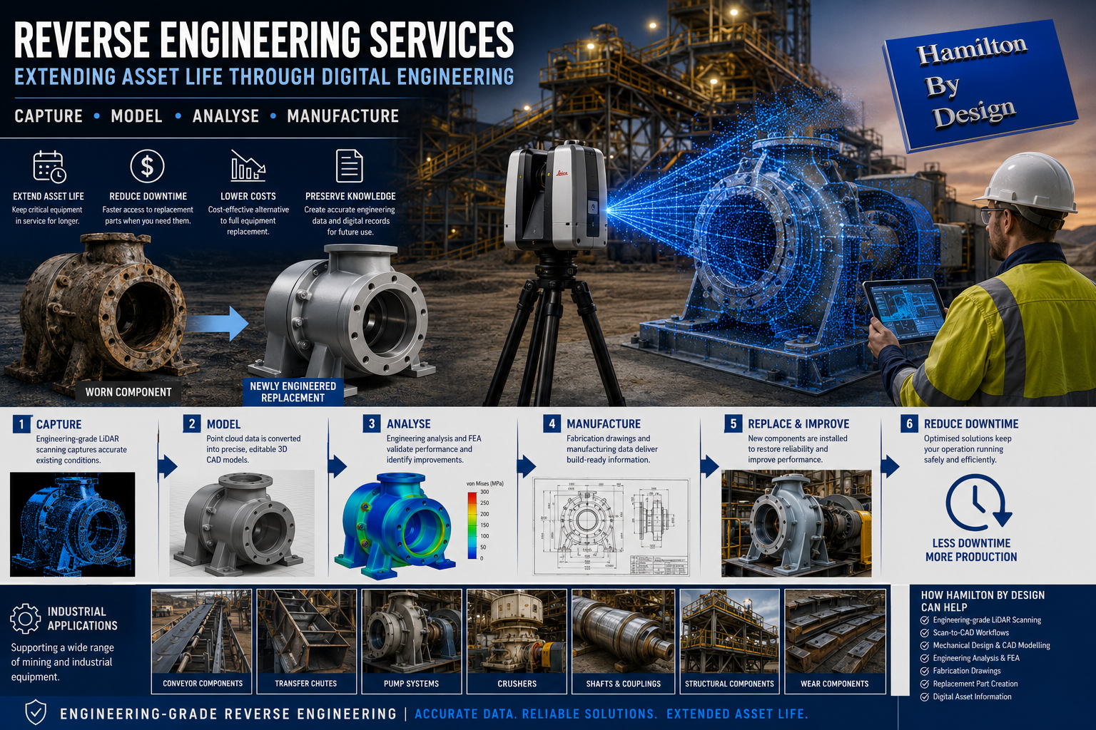
Engineering-Grade LiDAR Scanning for Existing Condition Capture
Hamilton By Design supports platform projects through engineering-grade 3D LiDAR scanning.
Scanning may capture:
- Structural steel
- Existing platforms
- Pipework
- Equipment
- Access systems
- Buildings
- Existing clearances
Measured information supports engineering decisions using actual site conditions rather than assumptions.
From Point Clouds to Platform Design
Captured information can be processed into engineering workflows through Scan-to-CAD systems.
This supports:
- Existing condition modelling
- Platform layouts
- Structural design
- Clash detection
- Access validation
- Fabrication drawings
Potential problems can often be identified digitally before fabrication begins.
Engineering Analysis and Validation
Platform systems frequently require engineering validation beyond simple geometry.
Hamilton By Design may support projects through:
- Structural assessment
- Finite Element Analysis (FEA)
- Load validation
- Design optimisation
- Fabrication documentation
The objective is delivering practical designs that perform in operating environments.
How Hamilton By Design Supports Industrial Platform Projects
Hamilton By Design combines practical engineering experience and digital engineering workflows including:
- Engineering-grade 3D LiDAR scanning
- Existing condition capture
- Scan-to-CAD workflows
- Mechanical and structural design
- Engineering analysis and simulation
- CAD modelling
- Fabrication documentation


Beyond Compliance
Industrial platform design should support more than standards compliance.
Successful designs support:
- Safer workplaces
- Better maintenance access
- Reduced downtime
- Improved operational efficiency
- Lower lifecycle costs
- Long-term asset performance
Standards establish minimum requirements.
Engineering adds value beyond them.
Better platform design supports better plant performance.

Our Clients: