Mechanical Engineering | 3D Scanning | 3D Modelling
Category: Engineering Mechanical
Mechanical Engineering focuses on the design, assessment, and improvement of mechanical systems and equipment used across industrial, infrastructure, and construction environments.
Content explores how mechanical engineering supports reliable operation, safe maintenance, and practical construction outcomes, particularly on brownfield and live sites where assumptions can lead to costly errors. The emphasis is on engineering that works in practice, not just theoretical design.
Engineering Accuracy for Hotel Renovations, Commercial Kitchens and Hospitality Facilities
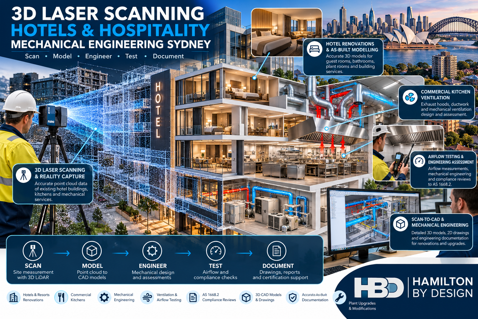
Hamilton By Design provides 3D laser scanning, mechanical engineering, reality capture and as-built documentation for hotels, restaurants, commercial kitchens and hospitality facilities throughout Sydney and New South Wales.
Whether you are renovating an existing hotel, upgrading a commercial kitchen, modifying mechanical ventilation or developing accurate engineering drawings, we help transform existing facilities into reliable 3D engineering models.
1. 3D Laser Scanning for Hotel Renovations
Our 3D LiDAR scanning services capture existing building geometry to support:
Hotel renovations and refurbishment projects
Guest room and bathroom upgrades
Commercial kitchen modifications
Plant rooms and mechanical services
Building services coordination
Accurate as-built 3D models and engineering drawings
Equipment replacement and installation planning
Using engineering-grade scanning technology, we develop detailed point clouds and CAD models that help reduce site measurement errors, installation clashes and costly rework.
2. Commercial Kitchen Ventilation and Fluid Flow Engineering
Hamilton By Design provides mechanical engineering support for commercial kitchens, restaurants and food preparation facilities.
Our services include:
Kitchen exhaust ventilation assessments
Airflow and fluid flow measurements
Exhaust hood performance testing
Ductwork and mechanical ventilation assessments
Mechanical ventilation compliance reviews against applicable Australian Standards, including AS 1668.2
Engineering calculations and technical reporting
Compliance documentation and certification where supported by the required inspections, testing and professional authority
We help hospitality operators understand whether their mechanical ventilation systems are performing as intended and identify opportunities for improvement.
3. 3D Modelling for Hospitality Refurbishments
Existing hotels and hospitality buildings often have incomplete or outdated engineering documentation.
Our scan-to-CAD workflow converts existing conditions into accurate digital engineering models suitable for refurbishment planning.
Deliverables can include:
Registered 3D point clouds
SolidWorks and AutoCAD models
2D general arrangement drawings
Mechanical equipment layouts
Ductwork and pipework routing
Fabrication and installation drawings
As-built engineering documentation
4. Engineering Support for Food Preparation Facilities
We assist commercial food preparation and hospitality facilities with mechanical equipment upgrades, ventilation improvements and modifications to existing infrastructure.
Our mechanical engineering services can support:
Food preparation equipment layouts
Mechanical plant upgrades
Extraction and ventilation systems
Equipment access and maintenance requirements
Mechanical guarding and safety improvements
Existing equipment reverse engineering
5. From 3D Scanning to Engineering Verification
Our integrated workflow combines site measurement, engineering assessment and documentation.
3D Laser Scanning → As-Built CAD Modelling → Mechanical Engineering → Testing and Verification → Engineering Documentation
This approach allows hotel owners, facility managers, architects and refurbishment contractors to work from reliable engineering information when planning modifications to existing facilities.
Servicing Sydney Hotels and Hospitality Facilities
Hamilton By Design supports hospitality projects throughout Sydney CBD, North Sydney, Chatswood, Parramatta, the Eastern Suburbs and surrounding NSW regions.
Engineering-grade 3D scanning for hotels, resorts,
restaurants and hospitality facilities. Capture
existing conditions for renovations, fit-outs,
mechanical services and as-built documentation.
Mechanical engineering, CAD drafting and 3D
scanning for existing commercial buildings,
equipment upgrades and engineering modifications
throughout Sydney and surrounding areas.
Capture walls, ceilings, structural interfaces,
ductwork and building services before refurbishment.
Support accurate design coordination, equipment
installation and as-built verification.
Convert 3D laser scanning data into coordinated
building information models. Document existing
layouts, mechanical services, plant rooms and
infrastructure for refurbishment planning.
Transform point-cloud measurements into detailed
CAD models and engineering drawings. Support
mechanical plant modifications, equipment
replacement and accurate installation planning.
Engineering support for mechanical equipment,
pipework, ductwork, plant layouts and upgrades.
Develop practical designs and documentation
using existing-condition measurements.
Engineering-grade reality capture for existing
commercial buildings. Support staged renovations,
services coordination, construction planning
and fit-out projects.
Mechanical design, reverse engineering and
fabrication-ready drawings for existing facilities.
Support equipment replacement, plant upgrades,
access improvements and engineering documentation.
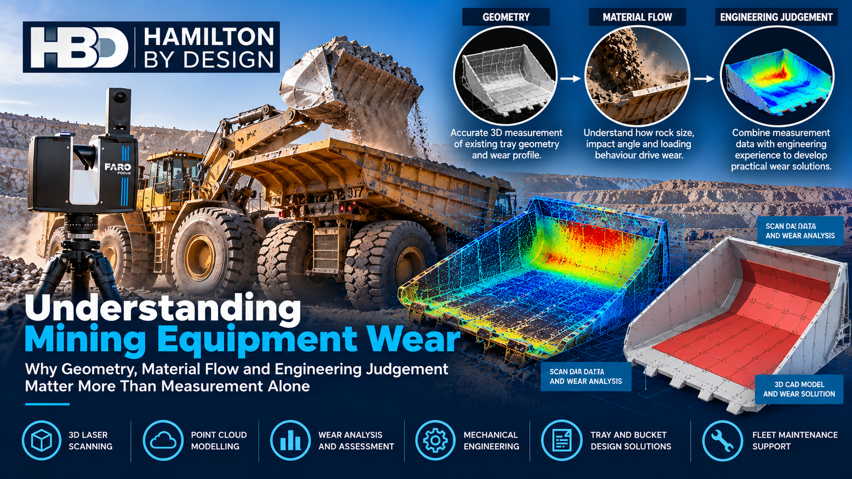
Understanding Mining Equipment Wear – Why Geometry, Material Flow and Engineering Judgement Matter More Than Measurement Alone
Today’s engineers have access to an exceptional range of measurement technologies.
3D LiDAR scanning, ultrasonic thickness testing, laser metrology, photogrammetry, vibration analysis and advanced CAD modelling allow equipment condition to be assessed with considerable detail.
However, at Hamilton By Design, we believe there is an important distinction between measuring wear and understanding why wear occurs.
A surveyor may identify a 15 mm variation in the geometry of a truck tray. A maintenance engineer may identify repeated wear plate replacement. A reliability engineer may establish that equipment service life is declining.
All three observations are valuable, but none necessarily explains why material is contacting a particular surface, why a component is deforming or whether a change in geometry could reduce the problem.
We consider that effective wear assessment requires a combination of accurate measurement, mechanical engineering, material-flow understanding and practical operating experience.
This philosophy also relates to our article on Project Management Challenges, where accurate existing-condition information and well-defined engineering requirements are important considerations.
1. Why Loader Buckets and Haul Truck Trays Experience Different Wear
Although loader buckets and haul truck trays handle similar materials, their operating conditions are fundamentally different.
A loader bucket penetrates and displaces material. Its cutting edge, teeth and protective components experience substantial digging forces, contact pressure, gouging and abrasive sliding.
A haul truck tray receives material, transports it and subsequently discharges it under gravity.
Wear consideration
Loader bucket
Haul truck tray
Ground engagement
High during digging
Generally none
Abrasive contact
Digging and material movement
Loading and discharge
Impact loading
Digging and filling
Material falling into tray
Material throughput
Combined production of multiple trucks
Individual truck production
Wear protection
Teeth, cutting edges, shrouds and liners
Floor liners, impact protection and wear plates
Main design consideration
Digging efficiency and durability
Payload efficiency and structural durability
Loader buckets commonly incorporate extensive replaceable wear protection because their ground-engaging surfaces experience severe abrasive contact.
However, this does not automatically mean the loader bucket structure will wear out before the truck tray.
2. Operating Cycles – One Loader Servicing Multiple Trucks
A common mistake when comparing wear is to assume that one loader operates with one truck.
In reality, a loader may service several haul trucks.
Consider the following hypothetical mining operation.
Operating parameter
Assumed value
Number of loaders
1
Number of haul trucks
5
Truck payload
120 tonnes
Effective bucket payload
20 tonnes
Bucket passes per truck
6
Complete truck cycle
30 minutes
Operating hours per day
20
Operating days per year
300
The truck cycle includes loading, hauling, tipping and returning. The example assumes sufficient loading capacity and no significant operational delays.
Calculation 1 – Truck Cycles
Each truck completes:
40 loads/day = (20 × 60) ÷ 30
Across five trucks:
5 × 40 = 200 truckloads/day
Calculation 2 – Daily Material Throughput
200 × 120 = 24,000 tonnes/day
Each individual truck carries:
40 × 120 = 4,800 tonnes/day
The loader therefore handles five times the material throughput of an individual truck tray.
Calculation 3 – Loader Bucket Cycles
Each truck requires six bucket passes.
200 × 6 = 1,200 bucket cycles/day
Each individual truck tray receives:
40 × 6 = 240 bucket discharge events/day
Annual Operating Exposure
Parameter
Loader bucket
Individual truck tray
Daily throughput
24,000 tonnes
4,800 tonnes
Annual throughput
7,200,000 tonnes
1,440,000 tonnes
Daily material-handling events
1,200
240
Annual material-handling events
360,000
72,000
The loader experiences five times the material throughput and material-handling events of an individual truck tray.
However, five times the throughput does not necessarily mean five times the wear.
The actual wear rate depends on material characteristics, contact pressure, particle movement, impact conditions and wear protection.
Operating Capacity and Haul Cycle Assumptions
The production calculations presented are based on a simplified mining fleet consisting of one wheel loader servicing five haul trucks, each with a payload of 120 tonnes.
The assumed 30-minute haul truck cycle includes loading, loaded travel, dumping, empty return travel and associated delays.
Actual cycle times depend on haul distance, road conditions, gradients, travel speeds, loading efficiency and equipment availability.
A shorter haul distance may increase the number of truckloads completed per shift, while a longer haul distance may reduce the frequency of loading and unloading events.
The loader must also have sufficient capacity to service the trucks at the required rate without becoming a production bottleneck.
These operating conditions directly influence the cumulative tonnes handled and the number of loading and unloading cycles experienced by each machine.
Consequently, wear exposure should be assessed using actual operating hours, material throughput, loading cycles and equipment geometry rather than operating time alone.
The calculations are illustrative and are not intended to represent the production performance of a particular mining operation.
3. Particle Size – Is It Controlled by the Production Process?
Particle-size distribution is an important factor in equipment wear.
In conventional open-pit mining, loaders and haul trucks often handle run-of-mine material before primary crushing.
Although drilling and blasting influence fragmentation, particle sizes may vary considerably.
In downstream processing operations, crushing and screening generally provide greater control over particle-size distribution.
Particle condition
Potential wear mechanism
Fine hard particles
Abrasive sliding and scratching
Medium angular particles
Cutting and gouging
Large rock fragments
Localised impact and deformation
Oversize material
High impact forces and potential structural damage
Wet or cohesive material
Material buildup and altered flow behaviour
Material hardness, particle shape, density and moisture content also influence wear.
A large angular rock may create significant localised impact damage, while smaller hard particles can produce substantial abrasive wear under sustained contact pressure.
4. The Cutting Tool Principle – Can Geometry Reduce Wear?
At Hamilton By Design, we consider that wear protection should not simply involve selecting harder steel or installing thicker wear liners.
An important design consideration is whether equipment geometry can reduce unnecessary abrasive contact.
A useful comparison can be made with cutting tools used on milling machines and lathes.
Cutting tools incorporate clearance or relief angles behind the cutting edge.
These angles reduce unnecessary rubbing between the tool and the newly machined surface.
The cutting edge performs the intended work, while the geometry behind it reduces unwanted contact.
We consider that this general design principle has relevance to bulk material handling equipment.
Loader Buckets
A loader bucket must penetrate material during digging.
However, the geometry of the cutting edge, heel, side protection and external wear components influences which surfaces experience abrasive contact.
Appropriate relief geometry and wear protection may reduce unnecessary rubbing and protect the main bucket structure.
Truck Trays, Hoppers and Transfer Chutes
The same broad principle can be considered when designing truck trays, hoppers and transfer chutes.
Where material trajectories can be controlled to reduce unnecessary contact with surrounding surfaces, localised abrasive wear may be reduced.
However, loose rock does not behave like a workpiece on a lathe.
Particles can rotate, rebound, collide and change direction.
Increasing clearance without considering the complete material-flow path may transfer wear to another location or increase impact severity.
The engineering objective should therefore be to establish suitable geometry and material movement rather than simply maximise clearance.
5. Vertical Ore Passes – Understanding Material Movement and Wear
Vertical and steeply inclined ore passes provide an interesting example of the relationship between geometry, movement and wear.
In underground mining, fragmented rock may be transferred between levels through gravity-fed ore passes.
Where material travels through a vertical section without continuous wall contact, abrasive sliding along those surfaces may be reduced.
However, this does not eliminate wear.
Material may strike the walls, rebound, change direction or impact receiving structures.
Calculation 4 – Gravitational Potential Energy
The gravitational potential energy of falling material is:
E = m × g × h
Where:
E = gravitational potential energy (joules)
m = material mass (kg)
g = gravitational acceleration (9.81 m/s²)
h = vertical drop height (m)
Consider a 100 kg rock falling through 10 metres.
E = 100 × 9.81 × 10
E = 9,810 J = 9.81 kJ
For a 30-metre drop:
E = 100 × 9.81 × 30
E = 29,430 J = 29.43 kJ
Vertical drop
Potential energy
5 m
4.91 kJ
10 m
9.81 kJ
20 m
19.62 kJ
30 m
29.43 kJ
These calculations illustrate the increase in gravitational potential energy with drop height. They do not establish the energy actually absorbed by a particular surface.
The actual impact conditions depend on particle trajectory, collisions, energy losses and contact geometry.
Reducing wall contact in one section of an ore pass may reduce abrasion there, while concentrating impact damage at another location.
For this reason, the entire material-flow path must be considered.
6. Surveying Measures Variation – Engineering Must Understand Wear
Modern surveying technologies allow engineers and surveyors to identify geometric differences with considerable accuracy.
However, a measured variation does not necessarily establish the mechanism responsible for that variation.
A surveyor may report that a truck tray floor has deviated by 15 mm from a reference model.
From a surveying perspective, this is a measurable geometric difference.
From a mechanical engineering perspective, several questions remain.
Has the steel worn away? Has the plate permanently deformed? Was the original geometry different from the reference? Has the structure moved under load?
Measured condition
Possible engineering explanation
15 mm truck tray floor deviation
Wear, deformation or original geometry
10 mm chute wall displacement
Structural movement, damage or installation variation
8 mm bucket cutting-edge reduction
Potential abrasive material loss
Ore pass wall irregularity
Excavation geometry, impact or wear
Reduced operating clearance
Deflection, movement or misalignment
Surveyors provide valuable expertise in dimensional measurement, spatial relationships and geometric accuracy.
However, surveying expertise does not automatically include specialist knowledge of tribology, mechanical wear, material flow or structural behaviour.
Equally, mechanical engineers depend on reliable dimensional information to make defensible engineering decisions.
At Hamilton By Design, we consider these disciplines complementary.
Surveying establishes the geometry. Engineering interpretation establishes what that geometry means for equipment performance.
7. Static Geometry Is Not the Same as Operating Geometry
A 3D scan generally captures equipment geometry at a particular moment.
However, equipment may move or deform under operating loads.
A static measurement does not automatically establish the minimum clearance available throughout the operating cycle.
Consider the following simplified example.
Parameter
Value
Initial static clearance
50 mm
Component A movement towards B
20 mm
Component B movement towards A
15 mm
Remaining clearance:
50 − 20 − 15 = 15 mm
The original 50 mm clearance has reduced to 15 mm under the assumed operating conditions.
Actual assessments must consider movement direction, load cases, thermal effects, tolerances and dynamic behaviour.
This illustrates why accurate measurement of stationary equipment is only one part of understanding its operating geometry.
A component may be manufactured and installed accurately yet experience excessive wear because its movement or material-flow conditions have not been adequately considered.
8. Modern Wear Measurement Technologies
Different technologies answer different engineering questions.
Technology
Primary application
3D LiDAR scanning
Large-scale geometry and deformation comparison
Metrology scanning
Detailed component geometry
Ultrasonic thickness testing
Remaining steel plate thickness
Vibration analysis
Rotating equipment condition and dynamic behaviour
CAD modelling
Geometry, clearance and modification design
Finite Element Analysis
Structural response under defined loads
Material-flow simulation
Particle trajectories and contact behaviour
No single technology provides every answer.
For example, 3D LiDAR scanning measures visible surface geometry but does not directly establish remaining steel thickness.
Ultrasonic thickness testing can measure remaining plate thickness at suitable locations but does not establish the complete three-dimensional deformation of a truck tray.
The appropriate measurement approach depends on the engineering objective.
9. Connecting Wear Assessment with Condition-Based Maintenance
Wear assessment is closely related to maintenance strategy.
ISO 18436-2 addresses qualification and assessment of personnel involved in vibration condition monitoring and diagnostics. It is not a truck tray wear assessment standard.
Nevertheless, the broader principles of condition monitoring, repeated inspection and reliability engineering are relevant to managing wear.
Calculation 5 – Establishing a Wear Rate
Assume a steel wear liner has the following measured thicknesses.
Parameter
Value
Initial thickness
20 mm
Remaining thickness
16 mm
Operating period
1,000 hours
Assumed minimum allowable thickness
10 mm
Material loss:
20 − 16 = 4 mm
Average wear rate:
4 ÷ 1,000 = 0.004 mm/hour
Equivalent to:
4 mm per 1,000 operating hours
If the wear rate remained constant, the estimated time to reach the assumed minimum thickness would be:
(16 − 10) ÷ 0.004
Estimated remaining operating time = 1,500 hours
This is a simplified linear projection, not a verified remaining-life prediction.
Actual wear may accelerate or reduce as operating conditions, material characteristics and component geometry change.
The minimum allowable thickness must also be established through an appropriate engineering assessment.
10. From Measurement to 3D Modelling and Engineering Improvement
3D scanning and modelling provide opportunities to move beyond documenting existing equipment condition.
For wear investigations, a practical workflow may include:
Establish the wear or deformation problem.
Capture existing geometry using suitable measurement methods.
Obtain thickness measurements and other inspection information where required.
Establish reference geometry from OEM drawings, historical scans or CAD models.
Review material properties, operating cycles and equipment movement.
Develop a 3D model of the equipment.
Investigate material trajectories, clearances and possible modifications.
Undertake appropriate engineering calculations or analysis.
Develop replacement components or modification drawings.
Monitor equipment performance following implementation.
This approach allows the engineering assessment to investigate not only what has changed but also why it has changed.
11. Why Every Wear Assessment Project Is Different
At Hamilton By Design, we recognise that every project is different, and no single wear assessment methodology should automatically be applied to all equipment.
Even two truck trays supplied by the same manufacturer may experience substantially different wear patterns.
Differences may result from:
Material hardness and particle-size distribution.
Loading height and impact conditions.
Material throughput and operating cycles.
Wear liner materials and configurations.
Equipment geometry and movement.
Previous repairs and maintenance.
Material moisture and flow behaviour.
Inspection history and available reference information.
A project intended to measure geometric deformation may require different inspection methods and deliverables from one investigating remaining plate thickness or structural fatigue.
Similarly, a transfer chute experiencing repeated liner failure may require an investigation of material trajectory rather than simply increasing wear liner thickness.
An engineering report prepared for one project should not automatically be considered representative of another.
The scope, methodology, calculations and deliverables should be developed around the actual equipment, operating conditions and engineering outcomes required.
12. Why Project Management Matters
Wear assessment is not only a technical challenge. It is also a project management consideration.
Poorly defined scopes, incomplete reference information and uncertainty about deliverables can lead to unnecessary work, delays and additional costs.
Our article Project Management Challenges discusses the importance of accurate information, planning and clear engineering requirements.
Before commencing a wear investigation, the client and engineering team should establish whether the objective is to:
Measure existing material loss.
Assess deformation.
Determine remaining serviceability.
Investigate recurring wear failures.
Develop replacement wear protection.
Modify equipment geometry.
Improve maintenance planning.
These objectives may require different engineering disciplines, inspection methods, calculations and reporting arrangements.
13. Hamilton By Design – Our Engineering Approach
Hamilton By Design provides mechanical engineering, 3D LiDAR scanning, reverse engineering and CAD modelling services for mining and industrial equipment.
Our approach considers the relationship between measured geometry, material characteristics and equipment operation.
We recognise that accurate measurement is essential, but the value of that information depends on how it is interpreted and applied.
For equipment such as loader buckets, haul truck trays, transfer chutes, hoppers and underground ore passes, an effective assessment may involve understanding material flow, identifying unnecessary contact, reviewing wear protection and investigating geometric improvements.
We believe the appropriate solution is not always to install thicker steel or harder wear liners.
In some applications, improvements to geometry, clearance, material trajectory or maintenance strategy may offer greater long-term benefits.
However, any proposed modification must be assessed against the equipment’s actual operating conditions, structural requirements and intended function.
Conclusion – Measuring Wear Is Only the Beginning
Today’s engineers have access to sophisticated technologies for measuring wear, deformation and equipment condition.
However, the ability to measure a geometric variation does not necessarily establish the cause of that variation.
A surveyor may identify where a component differs from its reference geometry. An inspection specialist may establish remaining plate thickness. A reliability engineer may identify recurring failures.
Mechanical engineering assessment brings these findings together with material behaviour, equipment geometry, operating movement and structural requirements.
The distinction is important.
A loader bucket may handle the combined material throughput of several haul trucks, but this does not automatically establish its relative wear rate.
A truck tray may experience fewer material-handling events but still suffer severe impact damage.
A vertical ore pass may experience reduced wall abrasion in one section while concentrating impact damage elsewhere.
A transfer chute may repeatedly wear through its liners because of an unfavourable material trajectory rather than insufficient liner hardness.
At Hamilton By Design, we believe the engineering objective should extend beyond measuring how much material has been lost. We should investigate why it was lost, whether unnecessary contact can be reduced and how equipment performance can be improved.
Every project is different.
The most appropriate assessment is one developed around the actual equipment, its operating conditions, the available evidence and the engineering outcomes required.
Measurement identifies the condition. Engineering explains the mechanism. Good design addresses the cause.
Engineering calculations in this article are illustrative examples only. They do not represent verified equipment performance data or substitute for project-specific engineering assessment.
Explore how Hamilton By Design combines mechanical
engineering, 3D LiDAR scanning, reverse engineering
and CAD modelling to support mining equipment wear
investigations, plant modifications and improved
material handling performance.
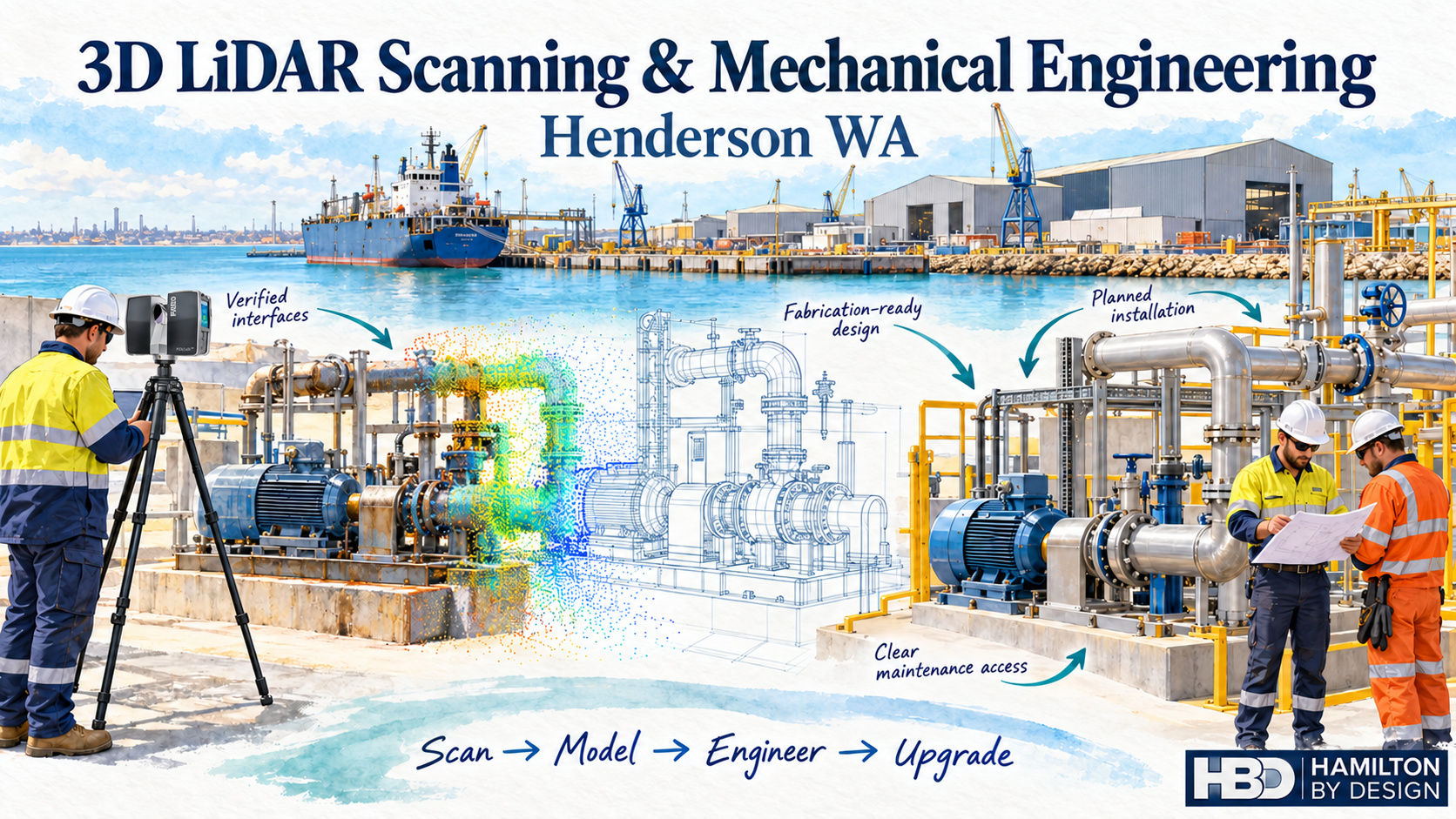
Practical engineering for marine facilities, fabrication workshops and industrial plant
Hamilton By Design provides 3D LiDAR scanning and mechanical engineering support in Henderson, Western Australia, helping businesses capture existing equipment, develop CAD models and plan modifications before fabrication begins.
Our approach connects site measurement with mechanical design. Whether you are replacing a pump skid, modifying workshop equipment or planning a new installation within an existing facility, we help turn site conditions into usable engineering information.
Scan → Model → Engineer → Upgrade
Supporting Henderson’s marine and industrial precinct
Henderson is home to the Australian Marine Complex, a major precinct supporting manufacturing, fabrication, assembly and maintenance for the marine, defence, energy and resources industries. These activities create a strong need for reliable information about existing equipment and installation spaces.
For businesses working in these environments, an equipment upgrade often involves more than designing a new component. The design must also consider surrounding pipework, access routes, maintenance space and connections to existing assets.
Older drawings may not reflect modifications made during years of operation. A bracket may have moved, a pipe route may have changed, or additional equipment may now occupy the intended installation area.
3D LiDAR scanning helps establish what exists before decisions are made about what comes next.
3D LiDAR scanning for existing facilities and equipment
Laser scanning captures visible surfaces as a three-dimensional point cloud. This provides a spatial reference that can be reviewed during layout planning, modelling and design.
For a Henderson project, the scanning scope could include:
Workshop interiors and machinery layouts.
Pump installations and mechanical equipment packages.
Existing pipework routes and connection areas.
Fabricated assemblies and equipment interfaces.
Platforms, access areas and maintenance clearances.
Machinery foundations and surrounding installation space.
Selected vessel machinery spaces, subject to access and project requirements.
The scan coverage is planned around the engineering task. A replacement equipment package may require detailed capture of a small installation area, while a workshop reconfiguration may require a broader record of the facility.
Capturing the relevant surroundings early helps identify constraints that could otherwise emerge during installation.
Mechanical engineering that uses the scan data
A point cloud becomes more useful when it informs a practical engineering decision.
Hamilton By Design combines LiDAR scanning with mechanical design, CAD modelling and drafting to support equipment modifications, brownfield upgrades and fabrication documentation.
For Henderson businesses, this approach can support:
Pump skid layouts and equipment integration.
Mechanical brackets, mounts and fabricated assemblies.
Conveyor and materials handling modifications.
Machine guarding and maintenance access improvements.
Replacement component modelling.
General arrangement and fabrication drawings.
Coordination of mechanical equipment with surrounding services.
The aim is to understand both the equipment and its working environment. A component may fit within the available footprint but still obstruct maintenance access, interfere with nearby pipework or be difficult to install.
Considering these issues during design gives the workshop and installation team clearer information before work begins.
Marine equipment upgrades and machinery space planning
Marine refits and equipment replacements can involve confined spaces, complex arrangements and limited installation access.
A new pump, auxiliary unit or mechanical package may need to fit around existing services while retaining access for operation and maintenance.
A scan-informed design review can help assess:
Available space around the proposed equipment.
Connections to existing mechanical systems.
Installation and removal routes.
Access to serviceable components.
Interference with surrounding equipment.
Areas requiring further inspection or measurement.
For example, replacing a pump package could involve scanning the existing installation, modelling the proposed equipment and reviewing the arrangement before preparing modification drawings.
The project scope should identify any vessel-specific design approvals or specialist reviews required.
Scan-to-CAD for fabrication and installation
Scan-to-CAD converts selected information from the point cloud into CAD geometry that can be used for design and documentation.
The level of modelling depends on the project. An equipment layout may need simplified representations of surrounding assets, while a replacement assembly may require detailed geometry at its connection points.
Potential deliverables include:
Existing-condition CAD models.
Proposed equipment layouts.
General arrangement drawings.
Mechanical fabrication drawings.
Installation interface details.
Point cloud datasets for coordination.
Updated drawings reflecting the agreed scope.
Agreeing the deliverables at the start helps ensure the model contains the information needed by the people designing, fabricating and installing the equipment.
Reverse engineering when drawings are missing
When an existing component has no reliable drawing, reverse engineering can help establish a basis for replacement or modification.
Typical applications include guards, brackets, covers, housings and fabricated mechanical assemblies.
The measurement method must suit the component. Terrestrial LiDAR is useful for larger equipment and its surroundings. Small features, machined fits and tight tolerances may require handheld metrology scanning, direct measurement or additional inspection.
A worn part also needs careful interpretation. Its current shape may differ from the intended design, so reproducing the measured geometry alone may reproduce wear or damage.
The objective is a usable replacement design supported by appropriate measurements.
Plan upgrades before the shutdown begins
For operating facilities, preparation can make a substantial difference to installation planning.
Capturing existing conditions before a shutdown allows the project team to review proposed layouts, identify uncertain interfaces and prepare drawings while the equipment remains available for inspection.
Useful questions include:
Can the new assembly reach its installation position?
Is there enough space for tools and fastening?
Can maintenance personnel access the equipment afterwards?
Are nearby services likely to interfere?
Which dimensions need direct verification before fabrication?
Scanning provides a record of accessible, visible surfaces. Hidden connections and obstructed areas should be identified so that additional checks can be planned.
Our project approach
1. Define the engineering task
We establish what is being changed, the required outputs and the critical interfaces.
2. Capture existing conditions
Site scanning and supplementary measurements are planned around access, visibility and the required accuracy.
3. Develop the model and design
Relevant existing geometry is modelled and used to develop the proposed mechanical arrangement.
4. Review the installation
The design is reviewed for fit, access, maintainability and coordination with surrounding equipment.
5. Prepare the agreed documentation
CAD files and drawings are issued to support the agreed fabrication, installation or planning scope.
Frequently asked questions
Can you scan a workshop before new machinery is installed?
Yes. Scanning can provide an existing-condition reference for assessing machinery layouts, service connections, access routes and maintenance space.
Can LiDAR data be used in SolidWorks or AutoCAD workflows?
Yes. Point cloud information can be used as a reference for developing CAD models and drawings. The required file formats and modelling scope should be agreed before work starts.
Do we need to stop operations for scanning?
This depends on the site. Some areas may be captured during normal operations, while moving equipment, restricted access or isolation requirements may require a planned shutdown or controlled access period.
Can scanning guarantee that a fabricated assembly will fit?
Fit depends on the complete measurement, design and fabrication process. Critical interfaces require appropriate verification, particularly where surfaces are hidden or tolerances are tight.
Can you provide mechanical design as well as scanning?
Yes. Hamilton By Design can combine scanning, CAD modelling, mechanical design and drafting within an agreed project scope.
What information should we provide for a quotation?
Provide the site location, photographs, available drawings, equipment details, proposed modifications, access requirements and required delivery date. Identify any critical dimensions or installation constraints.
Discuss your Henderson project
Planning a workshop upgrade, equipment replacement or mechanical modification in Henderson?
Hamilton By Design can help capture existing conditions and develop practical engineering information for your next stage of work.
Send us your photographs, drawings and project requirements to discuss 3D LiDAR scanning and mechanical engineering support in Henderson WA.
[Explore our Perth 3D scanning
3D LiDAR Scanning and Mechanical Engineering Henderson WA
Practical engineering for marine facilities, fabrication workshops and industrial plant
Hamilton By Design provides 3D LiDAR scanning and mechanical engineering support in Henderson, Western Australia, helping businesses capture existing equipment, develop CAD models and plan modifications before fabrication begins.
Our approach connects site measurement with mechanical design. Whether you are replacing a pump skid, modifying workshop equipment or planning a new installation within an existing facility, we help turn site conditions into usable engineering information.
Scan → Model → Engineer → Upgrade
Supporting Henderson’s marine and industrial precinct
Henderson is home to the Australian Marine Complex, a major precinct supporting manufacturing, fabrication, assembly and maintenance for the marine, defence, energy and resources industries. These activities create a strong need for reliable information about existing equipment and installation spaces.
For businesses working in these environments, an equipment upgrade often involves more than designing a new component. The design must also consider surrounding pipework, access routes, maintenance space and connections to existing assets.
Older drawings may not reflect modifications made during years of operation. A bracket may have moved, a pipe route may have changed, or additional equipment may now occupy the intended installation area.
3D LiDAR scanning helps establish what exists before decisions are made about what comes next.
3D LiDAR scanning for existing facilities and equipment
Laser scanning captures visible surfaces as a three-dimensional point cloud. This provides a spatial reference that can be reviewed during layout planning, modelling and design.
For a Henderson project, the scanning scope could include:
Workshop interiors and machinery layouts.
Pump installations and mechanical equipment packages.
Existing pipework routes and connection areas.
Fabricated assemblies and equipment interfaces.
Platforms, access areas and maintenance clearances.
Machinery foundations and surrounding installation space.
Selected vessel machinery spaces, subject to access and project requirements.
The scan coverage is planned around the engineering task. A replacement equipment package may require detailed capture of a small installation area, while a workshop reconfiguration may require a broader record of the facility.
Capturing the relevant surroundings early helps identify constraints that could otherwise emerge during installation.
Mechanical engineering that uses the scan data
A point cloud becomes more useful when it informs a practical engineering decision.
Hamilton By Design combines LiDAR scanning with mechanical design, CAD modelling and drafting to support equipment modifications, brownfield upgrades and fabrication documentation.
For Henderson businesses, this approach can support:
Pump skid layouts and equipment integration.
Mechanical brackets, mounts and fabricated assemblies.
Conveyor and materials handling modifications.
Machine guarding and maintenance access improvements.
Replacement component modelling.
General arrangement and fabrication drawings.
Coordination of mechanical equipment with surrounding services.
The aim is to understand both the equipment and its working environment. A component may fit within the available footprint but still obstruct maintenance access, interfere with nearby pipework or be difficult to install.
Considering these issues during design gives the workshop and installation team clearer information before work begins.
Marine equipment upgrades and machinery space planning
Marine refits and equipment replacements can involve confined spaces, complex arrangements and limited installation access.
A new pump, auxiliary unit or mechanical package may need to fit around existing services while retaining access for operation and maintenance.
A scan-informed design review can help assess:
Available space around the proposed equipment.
Connections to existing mechanical systems.
Installation and removal routes.
Access to serviceable components.
Interference with surrounding equipment.
Areas requiring further inspection or measurement.
For example, replacing a pump package could involve scanning the existing installation, modelling the proposed equipment and reviewing the arrangement before preparing modification drawings.
The project scope should identify any vessel-specific design approvals or specialist reviews required.
Scan-to-CAD for fabrication and installation
Scan-to-CAD converts selected information from the point cloud into CAD geometry that can be used for design and documentation.
The level of modelling depends on the project. An equipment layout may need simplified representations of surrounding assets, while a replacement assembly may require detailed geometry at its connection points.
Potential deliverables include:
Existing-condition CAD models.
Proposed equipment layouts.
General arrangement drawings.
Mechanical fabrication drawings.
Installation interface details.
Point cloud datasets for coordination.
Updated drawings reflecting the agreed scope.
Agreeing the deliverables at the start helps ensure the model contains the information needed by the people designing, fabricating and installing the equipment.
Reverse engineering when drawings are missing
When an existing component has no reliable drawing, reverse engineering can help establish a basis for replacement or modification.
Typical applications include guards, brackets, covers, housings and fabricated mechanical assemblies.
The measurement method must suit the component. Terrestrial LiDAR is useful for larger equipment and its surroundings. Small features, machined fits and tight tolerances may require handheld metrology scanning, direct measurement or additional inspection.
A worn part also needs careful interpretation. Its current shape may differ from the intended design, so reproducing the measured geometry alone may reproduce wear or damage.
The objective is a usable replacement design supported by appropriate measurements.
Plan upgrades before the shutdown begins
For operating facilities, preparation can make a substantial difference to installation planning.
Capturing existing conditions before a shutdown allows the project team to review proposed layouts, identify uncertain interfaces and prepare drawings while the equipment remains available for inspection.
Useful questions include:
Can the new assembly reach its installation position?
Is there enough space for tools and fastening?
Can maintenance personnel access the equipment afterwards?
Are nearby services likely to interfere?
Which dimensions need direct verification before fabrication?
Scanning provides a record of accessible, visible surfaces. Hidden connections and obstructed areas should be identified so that additional checks can be planned.
Our project approach
1. Define the engineering task
We establish what is being changed, the required outputs and the critical interfaces.
2. Capture existing conditions
Site scanning and supplementary measurements are planned around access, visibility and the required accuracy.
3. Develop the model and design
Relevant existing geometry is modelled and used to develop the proposed mechanical arrangement.
4. Review the installation
The design is reviewed for fit, access, maintainability and coordination with surrounding equipment.
5. Prepare the agreed documentation
CAD files and drawings are issued to support the agreed fabrication, installation or planning scope.
Frequently asked questions
Can you scan a workshop before new machinery is installed?
Yes. Scanning can provide an existing-condition reference for assessing machinery layouts, service connections, access routes and maintenance space.
Can LiDAR data be used in SolidWorks or AutoCAD workflows?
Yes. Point cloud information can be used as a reference for developing CAD models and drawings. The required file formats and modelling scope should be agreed before work starts.
Do we need to stop operations for scanning?
This depends on the site. Some areas may be captured during normal operations, while moving equipment, restricted access or isolation requirements may require a planned shutdown or controlled access period.
Can scanning guarantee that a fabricated assembly will fit?
Fit depends on the complete measurement, design and fabrication process. Critical interfaces require appropriate verification, particularly where surfaces are hidden or tolerances are tight.
Can you provide mechanical design as well as scanning?
Yes. Hamilton By Design can combine scanning, CAD modelling, mechanical design and drafting within an agreed project scope.
What information should we provide for a quotation?
Provide the site location, photographs, available drawings, equipment details, proposed modifications, access requirements and required delivery date. Identify any critical dimensions or installation constraints.
Discuss your Henderson project
Planning a workshop upgrade, equipment replacement or mechanical modification in Henderson?
Hamilton By Design can help capture existing conditions and develop practical engineering information for your next stage of work.
Send us your photographs, drawings and project requirements to discuss 3D LiDAR scanning and mechanical engineering support in Henderson WA.
Explore services supporting Henderson marine, fabrication and
industrial projects, from existing-condition capture to CAD
modelling and engineering documentation.
Explore scanning and engineering support for the nearby Kwinana
industrial region. Capture existing plant geometry to inform
equipment modifications and upgrade planning.
Document accessible existing conditions using terrestrial LiDAR.
Registered point clouds support layout review, design
coordination and asset documentation.
Convert captured site geometry into selected CAD models and
drawings. Define the deliverables needed for design,
modification and installation planning.
Explore drafting services for steelwork and industrial
infrastructure. Clear drawings help communicate geometry,
interfaces and fabrication requirements.
Develop useful engineering information from existing equipment
when drawings are incomplete or unavailable. Scanning supports
geometry capture for replacement and modification projects.
Develop mechanical CAD models for equipment, assemblies and
proposed upgrades. Modelling supports design review and
preparation of agreed engineering documentation.
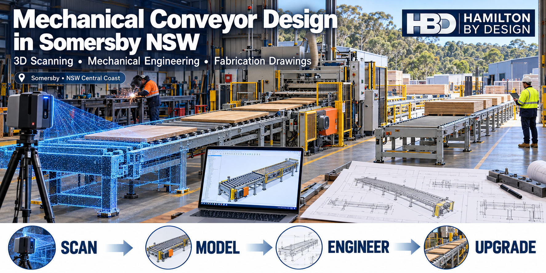
Conveyor engineering for manufacturing, fabrication and industrial plant upgrades
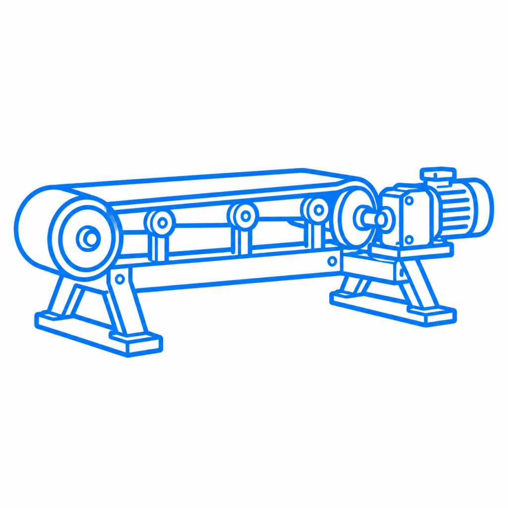
Hamilton By Design provides mechanical conveyor design in Somersby NSW, supporting manufacturers, fabricators and industrial businesses planning new equipment, production changes and upgrades to existing plant.
A conveyor must suit the product being handled and the factory in which it operates. Its layout needs to account for loading, discharge, machinery interfaces, guarding and maintenance access.
We bring together mechanical engineering, 3D laser scanning, SolidWorks modelling and fabrication drawings to develop conveyor arrangements around your operating requirements and existing site conditions.
From a workshop roller conveyor to a transfer chute modification or production-line extension, our approach follows a connected process:
Scan → Model → Engineer → Upgrade
Supporting Somersby’s manufacturing and industrial businesses
Somersby businesses work across a range of manufacturing, fabrication, processing and industrial applications. Each has different material handling requirements.
A conveyor carrying timber panels has different design needs from one transporting packaged products, fabricated steel components or process waste. Product dimensions, weight, surface condition and loading method all influence the arrangement.
Hamilton By Design can assist with projects involving:
Manufacturing and assembly lines.
Timber-panel and sheet-product handling.
Fabrication workshop transfer arrangements.
Packaging and production equipment.
Machinery infeed and discharge systems.
Industrial processing and bulk materials handling.
Recycling and process-waste transfer.
Replacement or modification of existing conveyors.
We begin by defining what the conveyor needs to achieve, then develop the mechanical design around that requirement.
Approximately 30 years of conveyor and materials handling experience
Hamilton By Design’s principal mechanical engineer, Anthony Hamilton, brings approximately 30 years of experience working with conveyors and materials handling equipment.
That experience informs a practical approach to conveyor design: understand the process, establish the loads, check the interfaces and prepare documentation that supports fabrication and installation.
For an existing factory, the challenge often extends beyond the conveyor itself. New equipment may need to fit between columns, pipework, production machinery and access routes while retaining room for maintenance.
Considering these constraints early helps identify design issues before equipment is fabricated.
New conveyor installations and production-line changes
Adding machinery can change how materials move through a factory.
A new cutting machine, filling line or packing station may require revised conveyor heights, different transfer arrangements or additional accumulation space. Changes in product size or production rate can also affect the suitability of an existing system.
Our mechanical conveyor design service can support:
Preliminary conveyor layouts.
Infeed and discharge arrangements.
Connections between production machines.
Conveyor extensions and relocations.
Transfer tables and transition sections.
Equipment frames and mounting details.
Guarding and removable access panels.
Fabrication and assembly documentation.
Where electrical controls or automation are required, mechanical interfaces are coordinated with your nominated specialists.
Design around the factory that exists today
Factory drawings do not always reflect the current installation.
Equipment may have been relocated, conveyors extended or services added without corresponding drawing updates. Designing from incomplete information can create clashes or incorrect connection details.
3D laser scanning can establish a measured reference for visible factory geometry, including machinery, conveyors, columns, platforms and surrounding services.
This information can support:
Conveyor route development.
Equipment positioning and elevation checks.
Identification of potential clashes.
Reviews of transfer and connection geometry.
Maintenance and component-removal clearances.
Installation planning.
Scanning is planned around the project’s intended use. Critical dimensions and close-tolerance interfaces may require direct measurement or additional verification.
A complete conveyor replacement is not always necessary.
A project may involve improving a transfer point, changing the discharge position, replacing a damaged frame or modifying the arrangement to suit new equipment.
Hamilton By Design can assist with:
Conveyor length and layout changes.
Revised loading and discharge arrangements.
Transfer chutes and product guides.
Roller mounting and support details.
Guard replacements and access improvements.
Wear liners and replaceable components.
Connections to bins, hoppers and machinery.
We review the existing equipment and the operating problem before developing the modification.
If throughput is increasing, the review may also need to consider the drive, conveyor components and supporting arrangements. Extending the geometry alone does not establish that the equipment is suitable for the revised duty.
Transfer chutes and bulk materials handling
For bulk material applications, conveyor performance depends partly on how material enters and leaves the belt.
Transfer geometry can affect loading position, impact, spillage, wear and blockages. Chute modifications therefore need to consider the material characteristics and operating conditions, together with available space.
Design considerations may include:
Material trajectory and receiving-belt alignment.
Loading conditions and impact zones.
Chute geometry and potential build-up.
Wear protection and liner replacement.
Sealing and dust-control interfaces.
Inspection, cleaning and maintenance access.
Specialist flow analysis can be considered where the project requires it.
Older conveyors may have missing drawings, unsupported components or modifications that are difficult to trace.
Reverse engineering can help establish the information needed to design replacements for selected components and assemblies.
Depending on the project, this may include:
Conveyor brackets and mounting plates.
Guards and covers.
Transfer chute bodies.
Roller mounting arrangements.
Frames and mechanical interfaces.
Worn or modified equipment components.
Measurement methods are selected to suit the component and required tolerances. Large assemblies and surrounding plant geometry may be suitable for LiDAR capture, while smaller features can require other measurement methods.
Wear and deformation are also considered. A replacement should reflect the intended function and geometry rather than automatically reproduce the component’s worn condition.
SolidWorks models and fabrication drawings
A 3D model allows the proposed arrangement to be reviewed before fabrication begins.
Hamilton By Design uses SolidWorks and AutoCAD to develop conveyor models and drawings appropriate to the agreed scope.
Deliverables can include:
Concept and detailed arrangement models.
General arrangement drawings.
Fabrication and assembly drawings.
Guard and sheet-metal details.
Chute and liner layouts.
Bills of materials.
Equipment interface details.
Installation reference dimensions.
Models can help production and maintenance personnel review the proposed layout, access arrangements and removal paths.
Drawing revisions and outstanding information are identified so the project team understands which documents are ready for review and which are approved for the next stage.
Maintenance access and machinery guarding
Maintenance requirements should influence the conveyor design from the beginning.
A compact installation may fit the available space but leave insufficient room to service bearings, adjust equipment or remove a drive assembly.
Design reviews can consider:
Access to bearings, drives and take-up arrangements.
Space for belt, roller and component replacement.
Guard attachment and removal.
Inspection and cleaning requirements.
Potential nip, crush and entanglement points.
Interfaces with walkways and workstations.
Isolation and servicing arrangements.
Applicable safety requirements and specialist assessments are established for the project. Safety controls, emergency stops and electrical systems require coordination with the relevant specialists.
Working with Somersby fabricators and installation teams
Clear drawings and interface information help connect engineering design with workshop fabrication.
Hamilton By Design can work with your nominated fabricator, machinery supplier and installation contractor to clarify connection details, assembly requirements and site constraints.
Early discussions can address:
Available fabrication processes.
Standard sections and purchased components.
Transport and lifting arrangements.
Workshop assembly versus site assembly.
Site access and installation sequence.
Shutdown requirements.
Dimensions requiring verification before manufacture.
We discuss the product or material, required throughput, loading method, operating conditions and the problem you want to solve.
For existing equipment, photographs, drawings and operator feedback provide useful starting information.
2. Establish site conditions
Where required, we visit the site, capture the relevant geometry and verify critical interfaces.
3. Develop the concept
We prepare the proposed arrangement and review its relationship with machinery, access routes and surrounding equipment.
4. Complete the mechanical design
The agreed concept is developed into detailed models, calculations and component arrangements appropriate to the scope.
5. Prepare the drawing package
Drawings and supporting information are issued through the agreed review process before fabrication.
6. Support fabrication and installation
We can assist with technical queries, agreed drawing updates and interface clarification as the project progresses.
Frequently asked questions
Can you design a conveyor around our existing machinery?
Yes. Site measurements, available drawings and 3D scanning can help establish the layout and connection requirements around installed equipment.
Can you modify an existing conveyor?
Yes. We can develop designs for extensions, transfer changes, component replacement and other agreed modifications. The existing equipment’s suitability for the revised duty needs to be assessed.
What if we do not have drawings?
Missing drawings do not necessarily prevent a project from proceeding. Scanning, direct measurement and reverse engineering can help establish the required information.
Do you provide fabrication drawings?
Fabrication drawings can form part of the scope, together with general arrangements, assembly details, bills of materials and CAD models.
Can you work with our local fabricator?
Yes. We can coordinate mechanical details and drawing requirements with your nominated fabricator and installation team.
Can scanning take place while the factory is operating?
In some circumstances, yes. Access, moving equipment, visibility and site safety requirements must be reviewed before the capture plan is agreed.
What information is needed for a quotation?
Useful inputs include photographs, existing drawings, product dimensions and weights, required throughput, proposed layout changes and your delivery timeframe.
Discuss your Somersby conveyor project
Are you planning a new conveyor, production-line change or upgrade to existing equipment?
Hamilton By Design can help establish the site conditions, develop the mechanical arrangement and prepare the models and drawings needed for the project.
Send through your photographs, available drawings and a brief description of the work required.
Related Engineering Services for Somersby Conveyor Projects
Explore Hamilton By Design services supporting conveyor design,
factory upgrades, equipment modifications and fabrication
projects in Somersby and across the NSW Central Coast.
Explore regional scanning services, registered point
clouds and as-built modelling for industrial upgrades,
interface reviews and installation planning.
Conveyor engineering for heavy manufacturing, automotive, fabrication and machinery
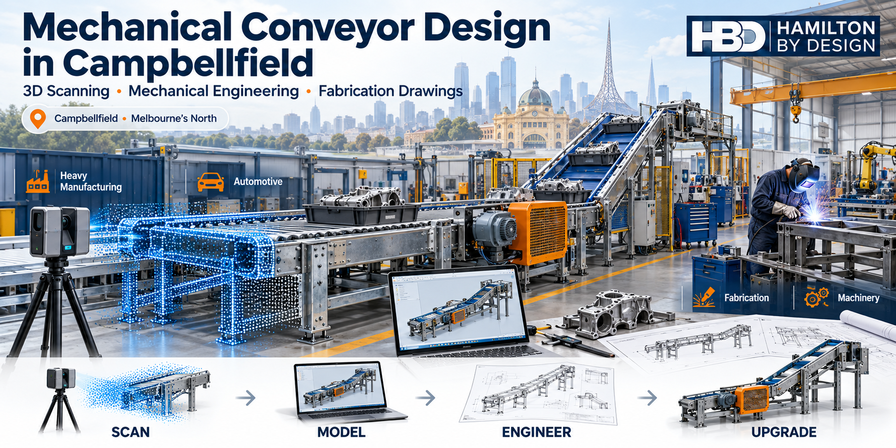
Hamilton By Design provides mechanical conveyor design in Campbellfield, helping manufacturers, fabricators and machinery businesses plan new installations, modify existing equipment and improve material handling.
A conveyor needs to do more than move a product from one point to another. It must suit the material, fit the available space, connect with surrounding machinery and allow practical access for operation and maintenance.
We bring together mechanical engineering, 3D LiDAR scanning, SolidWorks modelling and fabrication drawings to develop conveyor designs around those requirements.
Whether you are adding production equipment, replacing an ageing conveyor or changing your factory layout, our approach follows a connected process:
Scan → Model → Engineer → Upgrade
Practical conveyor design built on engineering experience
Hamilton By Design’s principal mechanical engineer, Anthony Hamilton, brings approximately 30 years of experience working with conveyors and materials handling equipment.
That experience supports a practical approach to design: understand the operating requirement, check the interfaces and develop documentation that fabricators and installation teams can use.
For Campbellfield businesses, conveyor projects may involve:
Moving manufactured components between workstations.
Feeding or discharging production machinery.
Handling fabricated assemblies and heavy parts.
Transferring products to inspection, packing or dispatch.
Collecting offcuts, scrap or process waste.
Modifying conveyors to accommodate new machinery.
Replacing worn components or unsupported equipment.
The design scope is developed around your process, site conditions and project priorities.
Conveyor design for Campbellfield’s industrial businesses
Heavy manufacturing
Heavy manufacturing applications require careful consideration of product weight, loading conditions, duty cycle and the working environment.
We can assist with conveyor frames, equipment supports, transfer arrangements and mechanical interfaces. Design considerations may include concentrated loads, impact during loading, uneven weight distribution and access for replacing wear components.
For an existing installation, we also consider how the proposed changes affect nearby equipment and supporting arrangements.
Automotive and component manufacturing
Automotive and component manufacturing applications often depend on controlled movement between machining, assembly, inspection and packing operations.
A conveyor may need to accommodate different component sizes, support a carrier or fixture, or transfer products at a defined working height.
Hamilton By Design can develop the mechanical layout and interface details, coordinating with machinery suppliers and electrical or automation specialists where those disciplines form part of the project.
Fabrication workshops
Fabrication workshops need material handling arrangements that suit their products and available floor space.
Applications may include roller conveyors beside cutting equipment, transfer tables between work areas, or handling arrangements for fabricated components.
We consider loading methods, forklift movements, crane access and the space required around the equipment. The aim is to develop a layout that supports production while retaining practical access through the workshop.
Machinery builders and equipment upgrades
For machinery builders, the conveyor is often one part of a larger system.
We can assist with conveyor infeed and discharge arrangements, mounting interfaces, transition sections, guarding and maintenance clearances.
Where existing machinery is being relocated or upgraded, capturing the surrounding geometry early helps establish how the new arrangement will fit.
Capture the existing factory before designing the upgrade
Older drawings may no longer reflect the equipment on site. Conveyors may have been extended, machinery relocated or services installed across a proposed route.
3D LiDAR scanning provides a measured reference for the visible site geometry, helping establish the relationship between conveyors, machinery, columns, platforms and surrounding services.
The scan data can support:
Factory and workshop layout planning.
Conveyor route and elevation development.
Identification of potential clashes.
Connection points with existing equipment.
Access and maintenance reviews.
Planning for prefabricated assemblies.
Scan coverage, accuracy requirements and critical dimensions are agreed for the project. Machined fits, bolt-hole positions and other close-tolerance interfaces may require additional measurement or verification.
This helps ensure the design uses measurement methods appropriate to each feature.
New conveyor layouts and existing conveyor modifications
A conveyor project does not always require a complete replacement.
Sometimes the most useful improvement is a revised transfer point, a new discharge arrangement or a change to the equipment layout.
Hamilton By Design can assist with:
Conveyor extensions and route changes.
Revised infeed and discharge heights.
Transfer chutes and transition sections.
Conveyor frames and mounting brackets.
Guarding and removable access panels.
Wear liners and replaceable components.
Interfaces with bins, hoppers and production machinery.
Before developing a modification, we review the operating problem and the existing arrangement. This helps establish whether the issue relates to geometry, product handling, wear, access or another part of the process.
When drawings are missing or equipment has become obsolete, reverse engineering can provide a basis for replacement design.
Depending on the project, this may include:
Conveyor brackets and mounting assemblies.
Guards, covers and enclosures.
Transfer chute bodies.
Roller mounting arrangements.
Frames and equipment interfaces.
Worn or modified mechanical components.
We combine suitable measurement methods with CAD modelling and engineering review to establish the replacement requirements.
A worn component should not automatically be reproduced exactly as measured. Wear, deformation and previous repairs need to be considered when deciding the intended replacement geometry.
Maintenance access is best considered while the conveyor layout is being developed.
A design review may examine access to bearings, drives and take-up arrangements, along with the space needed to remove guards or replace components.
Other considerations include:
Potential nip, crush and entanglement points.
Cleaning and inspection access.
Guard attachment and removal.
Product accumulation and spillage.
Isolation requirements.
Interfaces with walkways and workstations.
The applicable safety requirements and any specialist assessment are established for the project. Electrical controls, emergency stops and safety control systems require coordination with the relevant specialists.
Our conveyor design process
1. Define the operating requirement
We begin with the material or product being handled, required throughput, loading method, operating conditions and the problem you want to solve.
For an upgrade, photographs, existing drawings and feedback from operators are useful starting points.
2. Capture and verify site conditions
Where required, we scan the installation and check critical interfaces. This establishes the available space and the connection requirements.
3. Develop the concept
We prepare the proposed conveyor arrangement and review its relationship with production machinery, access routes and surrounding equipment.
4. Complete the mechanical design
The agreed concept is developed into detailed models, calculations and component arrangements appropriate to the scope. Specialist inputs are coordinated where required.
5. Prepare the drawing package
Drawings and supporting information are prepared for review and fabrication, with revisions clearly identified.
6. Support fabrication and installation
We can assist with technical queries, interface clarification and agreed drawing updates during fabrication and installation.
Supporting Campbellfield conveyor projects
Hamilton By Design supports Campbellfield businesses planning new production equipment, factory changes and conveyor upgrades.
We work with asset owners, maintenance teams, machinery suppliers and fabricators to connect the operating requirement with a practical mechanical design.
Yes. We can assess the existing arrangement and develop a design for extensions, transfer changes, guarding, component replacement or revised machinery interfaces. The scope depends on the condition and requirements of the installation.
Do you need existing conveyor drawings?
Existing drawings are helpful, but they are not always available. Site scanning, direct measurement and reverse engineering can help establish the information needed for design.
Can you design around our current factory layout?
Yes. Site measurements or 3D scanning can provide a reference for developing the conveyor arrangement around existing machinery and visible site constraints.
Do you provide fabrication drawings?
Fabrication drawings can form part of the agreed scope, together with general arrangements, assembly details and bills of materials.
Can you work with our fabricator or machinery supplier?
Yes. We can coordinate mechanical interfaces and drawing requirements with your nominated suppliers and installation team.
What information do you need for a quote?
Useful information includes photographs, existing drawings, product dimensions and weights, required throughput, proposed layout changes and your delivery timeframe.
Discuss your Campbellfield conveyor project
Are you planning a conveyor installation, machinery upgrade or factory layout change?
Hamilton By Design can help you establish the site conditions, develop the mechanical arrangement and prepare the documentation needed to move the project forward.
Send us your photographs, available drawings and a brief description of the work required.
Related Engineering Services for Campbellfield Conveyor Projects
Explore Hamilton By Design services supporting conveyor upgrades,
manufacturing equipment, factory layouts and fabrication projects
in Campbellfield and across Melbourne.
Develop mechanical designs for equipment modifications and plant
upgrades, with consideration for machinery interfaces,
maintenance access and installation.
Develop bulk material transfer arrangements with consideration
for chute geometry, wear protection, lining layouts,
dust control and maintenance access.
30 Years of Experience Developing Conveyors for Production Cells
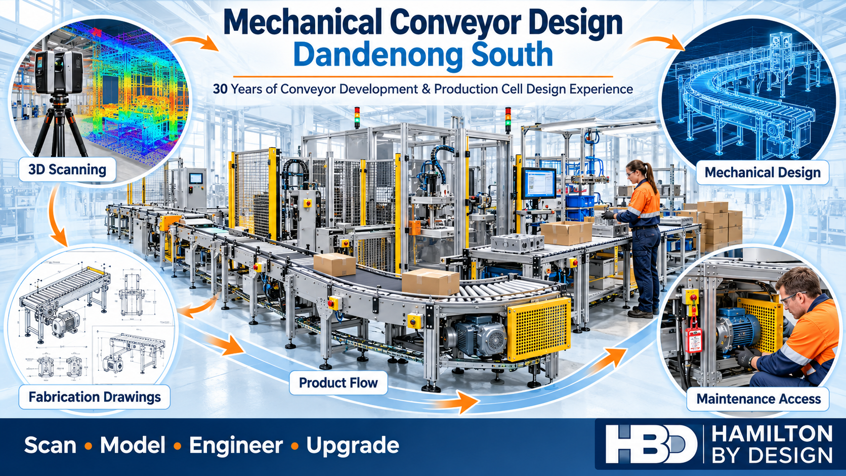
Hamilton By Design provides mechanical conveyor design in Dandenong South for manufacturers planning new production cells, equipment integration and conveyor upgrades. Our principal brings 30 years of experience developing and designing conveyors for production cells, supported by 3D scanning, SolidWorks modelling and fabrication drawings.
For 30 years, the principal at Hamilton By Design has worked on the development and design of conveyors for production cells. That experience shapes a practical approach to moving products between machines, workstations and process stages.
A successful conveyor design starts with understanding your production requirements. What needs to move? How quickly? In what orientation? How will operators interact with the equipment, and how will maintenance staff access it?
By combining mechanical design, 3D modelling, LiDAR scanning and engineering drawings, Hamilton By Design helps businesses develop conveyor arrangements that suit their products, processes and available factory space.
Conveyor Design That Fits Your Production Process
Conveyors connect individual machines into a working production system. Their performance depends on how well they integrate with the equipment upstream and downstream.
A conveyor may need to receive components from a machine, present products to an operator, feed a packaging station or transfer completed assemblies to the next process. Each application has different requirements for speed, spacing, loading and product handling.
Our design process considers:
Product dimensions, weight and orientation.
Required throughput and operating duty.
Conveyor length, width and working height.
Transfer points between conveyors and machines.
Available floor space and surrounding equipment.
Operator access and manual handling.
Cleaning, inspection and maintenance requirements.
Fabrication, assembly and installation constraints.
The aim is to develop a conveyor arrangement that supports the whole production cell.
New Conveyors and Existing Conveyor Modifications
Hamilton By Design can support new conveyor concepts and targeted modifications to existing systems.
Depending on the application, the mechanical design scope may include belt conveyors, roller conveyors, gravity transfers, product guides, support frames and machine interfaces.
For an existing production line, modifications might involve:
Extending or shortening a conveyor.
Changing the conveyor height or direction.
Connecting new machinery to an existing line.
Modifying product guides or transfer arrangements.
Replacing deteriorated frames and brackets.
Improving maintenance access.
Developing guarding and access arrangements.
Updating drawings to reflect the equipment installed.
Sometimes a targeted modification provides the improvement a business needs. We begin by understanding the issue and assessing the existing arrangement before developing the design scope.
Integrating Conveyors into Production Cells
Production-cell conveyor design requires attention to the interaction between people, products and machinery.
For example, installing a faster conveyor will not necessarily increase output if the next machine cannot accept products at that rate. Similarly, a compact layout may save floor space while making cleaning or maintenance difficult.
Hamilton By Design considers the proposed conveyor within the wider production process, including:
Product Flow
We assess how products enter, travel through and leave the conveyor. Product stability, spacing and transfer geometry can influence whether the arrangement operates smoothly.
Machine Interfaces
Conveyor heights, entry points and discharge positions need to coordinate with the equipment they serve. Mechanical interfaces should be established early so that brackets, guides and transition details can be developed around agreed dimensions.
Operator Interaction
Loading, unloading, inspection and assembly tasks influence conveyor positioning. The layout should account for how operators carry out their work and move through the production area.
Maintenance Access
Bearings, rollers, drives and adjustment points need suitable access. Considering component removal and maintenance tasks during design helps avoid difficult arrangements after installation.
Electrical controls, sensors and automation interfaces can be coordinated with the client’s nominated electrical or automation specialists.
3D Scanning Before Conveyor Upgrades
When a new conveyor must fit into an existing factory, reliable information about the surrounding equipment is valuable.
Older drawings may not show machinery relocations, additional services or previous modifications. Measuring only the proposed conveyor footprint can also miss obstructions above or beside it.
Hamilton By Design’s 3D laser scanning services can capture visible existing conditions to support layout planning and mechanical design.
A scan can help establish:
Existing conveyor routes and elevations.
Machine positions and external geometry.
Columns, walls and nearby services.
Available space for new equipment.
Access routes and installation constraints.
Potential clashes with surrounding plant.
Capturing the factory before finalising a layout allows proposed equipment to be assessed against the existing environment.
Where close-tolerance interfaces are required, critical dimensions can be identified for separate verification. This is particularly relevant to mounting holes, shafts, bearings and machined connections.
3D Modelling for Conveyor Layouts
A coordinated 3D model makes the proposed conveyor arrangement easier to review before fabrication begins.
Hamilton By Design uses SolidWorks and CAD tools to develop mechanical assemblies and communicate the relationship between conveyors, machines, support frames and surrounding plant.
Models can support reviews of:
Overall conveyor geometry.
Product entry and discharge positions.
Frame and support arrangements.
Drive locations and component access.
Guarding envelopes.
Installation and assembly space.
Interfaces with existing equipment.
Production staff, maintenance personnel and fabricators can review the same arrangement and identify practical issues while changes are still straightforward to make.
For businesses in Dandenong South planning a production-cell upgrade, this provides an opportunity to resolve layout questions before committing to fabrication.
Mechanical Design and Fabrication Drawings
Once the arrangement is agreed, the design can progress into drawings and documentation appropriate to the project.
Our mechanical drafting services can support the manufacture, assembly and installation of new or modified conveyor equipment.
Depending on the agreed scope, deliverables may include:
General arrangement drawings.
Conveyor assembly drawings.
Frame and bracket fabrication details.
Sheet-metal and product-guide details.
Component drawings.
Bills of materials.
DXF cutting profiles.
STEP files for supplier coordination.
Installation and interface drawings.
The documentation package is established around the needs of the client, fabricator and installation team.
Designing for Maintenance and Practical Operation
A conveyor should be assessed over its working life, including the tasks needed to keep it operating.
During design, we consider questions such as:
Can the belt or rollers be replaced without dismantling surrounding equipment?
Are adjustment points accessible?
Can debris be removed from beneath the conveyor?
Is there space to inspect and maintain the drive?
Can guards be removed and reinstated for authorised maintenance?
Are wear components practical to source and replace?
These decisions affect maintenance effort, downtime and the usefulness of the final installation.
Machinery hazards and guarding requirements should also be considered during design. Conveyor safety depends on the complete arrangement, including access, controls, operating procedures and maintenance tasks.
A Practical Process from Concept to Installation Support
Hamilton By Design’s mechanical engineering consulting can be tailored to a focused conveyor modification or a broader production-cell project.
1. Define the Requirement
We discuss the product, production target, existing problems, available space and project timing.
2. Establish Existing Conditions
Relevant drawings, measurements and site information are reviewed. Where useful, 3D scanning captures the surrounding plant.
3. Develop the Concept
Proposed layouts and mechanical arrangements are developed for review with the people who operate and maintain the equipment.
4. Complete the Detailed Design
The agreed concept progresses into component selection, mechanical details and the required design checks.
5. Prepare the Documentation
Models, drawings and supporting information are prepared for the agreed fabrication and installation scope.
6. Support Fabrication and Installation
Where included, we assist with technical queries and review changes that arise during manufacture or installation.
Frequently Asked Questions
Can Hamilton By Design modify an existing conveyor?
Yes. We can assess the existing arrangement and develop mechanical modifications to suit a new machine, revised product flow or changed production requirement.
Do we need a 3D scan for every conveyor project?
No. A straightforward conveyor may be designed using verified measurements and suitable drawings. Scanning is particularly useful where the factory is congested, records are incomplete or several equipment interfaces need coordination.
Can you design a conveyor around our available factory space?
Yes. Available space, equipment positions, access and maintenance requirements can be incorporated into the layout process. Providing information early helps establish the constraints before detailed design begins.
Can you provide drawings for our preferred fabricator?
Yes. The drawing package can be developed around the agreed fabrication scope and your fabricator’s requirements.
Can you assist before we purchase new machinery?
Yes. Early layout planning can help establish conveyor interfaces, working heights, access requirements and available installation space before machinery positions are finalised.
Discuss Your Conveyor Project in Dandenong South
Are you planning a new production cell, adding machinery or modifying an existing conveyor?
Hamilton By Design brings together 30 years of conveyor development and design experience, mechanical engineering, 3D scanning, CAD modelling and fabrication documentation.
Send us your existing drawings, photographs or a description of the production issue. Include the product being handled, your required throughput and any installation deadline so we can discuss a suitable scope.
Develop practical mechanical designs for conveyor modifications,
equipment interfaces and plant upgrades, with attention to
fabrication, installation and maintenance.
Capture existing machinery, conveyors and surrounding factory
geometry to support layout planning and identify spatial
constraints before detailed design.
Turn agreed conveyor designs into general arrangements,
component details and fabrication drawings that communicate
how equipment is built and assembled.
Connect conveyor development with broader production
requirements, including machinery integration, equipment
layouts and improvements to existing processes.
Assess stresses and deflections in mechanical components,
brackets and equipment frames where engineering analysis
is required for the proposed design.
For conveyors handling bulk materials, explore chute,
hopper and transfer-point design with consideration
of material flow, wear and maintenance access.
To provide the best experiences, we use technologies like cookies to store and/or access device information. Consenting to these technologies will allow us to process data such as browsing behaviour or unique IDs on this site. Not consenting or withdrawing consent, may adversely affect certain features and functions.
Functional
Always active
The technical storage or access is strictly necessary for the legitimate purpose of enabling the use of a specific service explicitly requested by the subscriber or user, or for the sole purpose of carrying out the transmission of a communication over an electronic communications network.
Preferences
The technical storage or access is necessary for the legitimate purpose of storing preferences that are not requested by the subscriber or user.
Statistics
The technical storage or access that is used exclusively for statistical purposes.The technical storage or access that is used exclusively for anonymous statistical purposes. Without a subpoena, voluntary compliance on the part of your Internet Service Provider, or additional records from a third party, information stored or retrieved for this purpose alone cannot usually be used to identify you.
Marketing
The technical storage or access is required to create user profiles to send advertising, or to track the user on a website or across several websites for similar marketing purposes.