3D Scanning for Engineering in Construction โ€“ Accurate As-Built Information

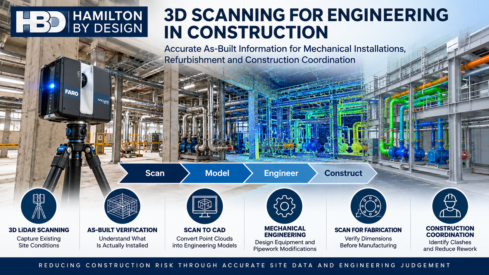
3D LiDAR scanning for engineering in construction by Hamilton By Design, showing a FARO scanner, as-built point clouds, mechanical installations, scan-to-CAD modelling and construction coordination.

3D LiDAR Scanning | Mechanical Engineering | Construction Coordination | Scan to CAD | Refurbishment and Plant Upgrades

Accurate Existing-Condition Information Before Construction Begins

Blue 3D LiDAR scanner icon on a tripod with scanning waves

Construction projects frequently involve working around existing structures, mechanical equipment, pipework, services and building infrastructure.

Whether installing new equipment, modifying an industrial facility or refurbishing an existing building, one of the greatest engineering challenges is understanding what is actually present on site.

Original construction drawings may be incomplete, outdated or inconsistent with the installed arrangement. Equipment may have been relocated, pipework modified and structures altered over many years.

These uncertainties can lead to dimensional conflicts, fabrication errors, installation delays and expensive rework.

3D scanning for engineering in construction provides a practical method of capturing existing site geometry before design, fabrication and installation activities begin.

At Hamilton By Design, we combine 3D LiDAR scanning, point cloud processing, mechanical engineering and 3D CAD modelling to help construction and engineering teams make better-informed decisions.

Our approach follows a straightforward engineering workflow:

Scan โ†’ Model โ†’ Engineer โ†’ Upgrade

Rather than treating scanning as an isolated surveying activity, we use captured site information to support practical engineering outcomes.


1. How Is 3D Scanning Used for Engineering in Construction Projects?

3D scanning is used in construction to capture the geometry of existing buildings, industrial facilities, mechanical installations and structural interfaces.

A terrestrial 3D LiDAR scanner records millions of spatial measurements to generate a three-dimensional point cloud representing visible site conditions.

This information can support:

  • Existing-condition and as-built documentation.
  • Mechanical equipment installation and replacement.
  • Pipework modifications and routing.
  • Conveyor and materials-handling upgrades.
  • Plant refurbishment and brownfield construction.
  • Equipment access and maintenance planning.
  • Construction coordination and clash identification.
  • Development of 2D drawings and 3D engineering models.

For example, when installing a new pump skid inside an operating industrial facility, the project team may need to establish available floor space, pipework connection locations, structural clearances and maintenance access.

A registered point cloud provides a common spatial reference for developing and checking the proposed installation.

This can reduce reliance on repeated manual measurements and assumptions about existing site geometry.

Engineering Application: Mechanical Equipment Installation

Consider a construction project involving the replacement of existing mechanical equipment.

Before the new equipment is fabricated or delivered, engineers may need to confirm:

  • Equipment footprint and mounting locations.
  • Existing pipework connections and flange positions.
  • Structural obstructions.
  • Available lifting and installation clearances.
  • Access for operation and maintenance.

3D scanning provides geometric information that can be incorporated into a CAD environment to support these assessments.

However, scanning does not replace engineering verification of loading, structural capacity, tolerances or installation requirements.


2. What Are the Benefits of 3D Laser Scanning for Accurate As-Built Information in Construction?

One of the principal benefits of 3D laser scanning is the ability to establish a detailed digital record of existing site conditions.

Traditional drawings often represent the original design intent rather than the actual installed arrangement.

During construction, small differences between drawings and site conditions can become significant when equipment, pipework or prefabricated components must fit within constrained spaces.

Benefits of 3D Scanning for Construction

Construction challenge3D scanning contribution
Outdated construction drawingsCaptures visible existing geometry for comparison and documentation
Limited access to existing equipmentRecords accessible surfaces and surrounding spatial relationships
Pipework installation conflictsSupports identification of routing and clearance constraints
Mechanical equipment replacementHelps establish existing interfaces and installation envelopes
Fabrication dimensional uncertaintyProvides reference geometry for design and dimensional checks
Restricted maintenance accessSupports assessment of equipment removal and maintenance envelopes
Multiple construction disciplinesProvides a common spatial reference for coordination
Brownfield modificationsHelps identify existing obstructions before construction

Understanding Scanning Accuracy

Accuracy should always be considered in the context of the engineering application.

A scanner’s individual measurement specification is not necessarily the accuracy of a complete registered point cloud.

For industrial scanning projects, overall accuracy depends on factors including:

  • Scanner capability and calibration.
  • Distance to the measured surfaces.
  • Surface characteristics and visibility.
  • Scan registration methodology.
  • Site geometry and environmental conditions.
  • Control survey arrangements where required.

For typical industrial projects, Hamilton By Design may work with registered datasets having practical accuracy expectations in the order of several millimetres, depending on site conditions and the scanning methodology.

Critical fabrication interfaces, machined surfaces, bolt-hole patterns and tight-tolerance connections may require additional dimensional verification using appropriate measurement equipment.

This distinction is important because reliable engineering outcomes depend on selecting a measurement method appropriate to the required tolerance.


3. How Does 3D Scanning Improve Mechanical Installation and Construction Coordination?

Mechanical installation projects frequently require new equipment to interface with existing structures and services.

These interfaces can become particularly challenging in operating factories, processing plants, warehouses and other established facilities.

3D scanning improves construction coordination by allowing engineers and contractors to assess proposed equipment arrangements against captured existing geometry.

Mechanical Equipment and Pipework

Point cloud information can be used to develop or position 3D CAD models of:

  • Pump skids and mechanical equipment.
  • Pipework and supporting structures.
  • Conveyors and transfer stations.
  • Mechanical platforms and access arrangements.
  • Industrial ventilation equipment.
  • Equipment guarding and maintenance access.
  • Structural support interfaces.

The proposed equipment model can then be reviewed alongside the point cloud to identify potential geometric conflicts.

Construction Coordination and Clash Detection

For construction projects involving several disciplines, a shared digital model can improve communication between mechanical engineers, structural engineers, building contractors and installation teams.

For example, a proposed pipework route may conflict with an existing beam, cable tray, ventilation duct or maintenance access zone.

Identifying these conflicts during design is generally preferable to discovering them during installation.

Hamilton By Design can develop CAD models from point cloud data and provide model information suitable for coordination workflows using software such as Autodesk Navisworks.

The objective is not simply to create a digital model. It is to identify construction constraints before they become site problems.

Example: Installing New Equipment in an Existing Factory

Consider a project requiring the installation of a new production machine.

The design team may need to coordinate the machine footprint, access requirements, existing services, mechanical connections and supporting infrastructure.

By scanning the installation area and incorporating the proposed equipment model, the team can review the installation arrangement before fabrication and mobilisation.

This supports more informed decisions about equipment positioning, service modifications and construction sequencing.


4. Can 3D LiDAR Scanning Reduce Construction Errors During Refurbishment and Plant Upgrades?

Yes. When appropriately planned and verified, 3D LiDAR scanning can help reduce construction errors associated with inaccurate existing-condition information.

Refurbishment and brownfield construction projects are particularly exposed to dimensional uncertainty because the original facility may have undergone numerous undocumented modifications.

Refurbishment and Brownfield Construction

Typical applications include:

Industrial Plant Upgrades

Capturing existing mechanical equipment, conveyors, platforms, pipework and supporting infrastructure before modifications are designed.

Commercial Building Refurbishment

Recording existing plantrooms, mechanical service spaces and building interfaces to assist with proposed equipment replacements.

Mechanical Services Modifications

Supporting the development of new pipework routes, ventilation arrangements and equipment layouts within existing facilities.

Construction of Equipment Supports

Establishing existing interface geometry before new mechanical support arrangements are designed and detailed.

Shutdown and Installation Planning

Providing dimensional information to help plan equipment removal, replacement and installation activities.

Reducing Rework Through Better Engineering Information

Construction rework can occur when fabricated components do not match existing site conditions.

For example, a prefabricated pipe spool may be manufactured using outdated dimensions.

When the spool arrives on site, the existing connection points may not align with the assumed arrangement.

A properly scoped 3D scanning and dimensional verification process can help identify these discrepancies before fabrication.

However, the point cloud must be sufficiently complete and accurate for the intended engineering purpose.

Where critical dimensions cannot be reliably established from the scan, additional site measurements should be undertaken.

3D scanning helps reduce geometric uncertainty, but it does not eliminate the need for engineering judgement, appropriate tolerances and construction verification.


5. Who Provides 3D Scanning and Mechanical Engineering Services for Construction Projects in Australia?

Hamilton By Design provides 3D LiDAR scanning, point cloud processing, 3D CAD modelling and mechanical engineering services for industrial and commercial construction projects across Australia.

Our services are particularly relevant where construction activities involve existing mechanical equipment, plant modifications, industrial refurbishment and coordination between new and existing infrastructure.

Unlike workflows that stop at the delivery of a point cloud, Hamilton By Design can assist with subsequent mechanical design and drafting activities.

Our Construction Engineering Services

ServiceEngineering application
3D LiDAR scanningCapture existing site conditions
Point cloud registrationCombine individual scans into a coordinated dataset
Scan to CADDevelop CAD geometry from captured information
Mechanical engineering designDevelop equipment modifications and mechanical arrangements
3D CAD modellingModel equipment, pipework and installation interfaces
General arrangement drawingsCommunicate proposed equipment layouts and interfaces
Fabrication drawingsDetail mechanical components for manufacture where included in scope
Construction coordinationReview proposed installations against existing geometry
Reverse engineeringReconstruct existing components or equipment geometry
Engineering design reviewAssess relevant mechanical constraints and design requirements

Our mechanical engineering services can support projects involving industrial facilities, manufacturing plants, materials-handling systems and commercial mechanical installations.

Where structural design, certification or specialist engineering services are required, these should be undertaken or verified by appropriately qualified professionals within the relevant discipline.


From Point Cloud to Construction-Ready Engineering Information

A successful scanning project should begin with an understanding of the engineering decision the information must support.

At Hamilton By Design, we approach construction scanning through five stages.

Stage 1 โ€“ Define the Engineering Requirements

Identify the proposed construction activity, required deliverables, critical interfaces, accuracy expectations and access constraints.

Stage 2 โ€“ Capture Existing Site Conditions

Undertake 3D LiDAR scanning of the relevant installation area, including visible equipment, pipework, structural interfaces and surrounding obstructions.

Stage 3 โ€“ Register and Process the Point Cloud

Process the captured scans into a coordinated point cloud dataset suitable for engineering review and modelling.

Stage 4 โ€“ Develop Engineering Models and Drawings

Use the point cloud as a reference to develop 3D CAD models, equipment arrangements, general arrangement drawings and other agreed engineering deliverables.

Stage 5 โ€“ Support Construction and Installation

Provide the agreed engineering information to assist fabrication planning, installation coordination and construction review.

Where required, additional dimensional checks can be incorporated before critical fabrication or installation activities.

This workflow helps connect digital site capture with practical engineering outcomes.


3D Scanning Compared with Traditional Site Measurement

Both traditional measurement and 3D scanning have important roles in construction engineering.

ConsiderationTraditional site measurement3D LiDAR scanning
Data captureSelected individual dimensionsDense spatial measurements of visible surfaces
Complex geometryMay require numerous measurementsCan capture extensive geometric detail
Site documentationNotes, sketches and photographsRegistered point clouds and associated imagery where available
Design coordinationBased on recorded dimensionsSupports spatial review with CAD models
Repeat measurementsMay require additional site visitsExisting scan data may permit later measurements where geometry was adequately captured
Critical tolerancesPrecision tools can directly verify featuresAdditional verification may still be necessary
Engineering deliverablesDrawings and dimensional recordsPoint clouds, CAD models and drawings as scoped

The most effective approach is often a combination of both methods.

3D scanning captures the broader installation environment, while conventional dimensional measurement verifies critical interfaces.


Where Is 3D Scanning Most Valuable in Construction?

3D scanning can be particularly valuable when a project involves:

  • An existing facility with incomplete or outdated drawings.
  • Installation of equipment within restricted spaces.
  • Multiple mechanical and structural interfaces.
  • Complex pipework routing.
  • Prefabricated components requiring accurate site interfaces.
  • Construction activities during limited shutdown periods.
  • Brownfield modifications and equipment replacement.
  • Coordination between engineering disciplines.

The value of scanning increases when the captured information is used early enough to influence engineering design and construction planning.

Scanning after a dimensional conflict has already occurred may help diagnose the problem, but scanning before fabrication provides an opportunity to avoid it.


Frequently Asked Questions About 3D Scanning in Construction

Is 3D scanning suitable for existing industrial buildings?

Yes. 3D LiDAR scanning can capture visible geometry within factories, warehouses, mechanical plantrooms and industrial facilities to support refurbishment and modification projects.

Can a point cloud be converted into a SolidWorks or AutoCAD model?

Yes. Point cloud data can be used as a reference for developing CAD models in software such as SolidWorks and AutoCAD. The level of modelling detail depends on the engineering scope and intended deliverables.

Does 3D scanning replace construction drawings?

No. A point cloud represents measured site geometry. Engineering drawings communicate design intent, dimensions, materials, tolerances and fabrication or installation requirements. The two serve different purposes.

Can 3D scanning help with prefabricated pipework?

Yes. Scanning can support the identification of existing pipework routes, surrounding obstructions and connection locations. Critical flange dimensions, orientations and fabrication tolerances should be independently verified as required.

Can 3D scanning identify construction clashes?

Yes. By reviewing proposed CAD geometry against a suitably complete and registered point cloud, engineers can identify potential spatial conflicts. This does not guarantee detection of every clash, particularly where existing features are concealed or insufficiently captured.

Is 3D scanning suitable for small construction projects?

Yes. The value depends on the complexity of the existing conditions, dimensional risks and intended engineering deliverables rather than project size alone.

Does Hamilton By Design provide both scanning and engineering?

Yes. Hamilton By Design provides 3D LiDAR scanning, point cloud processing, mechanical engineering design, CAD modelling and drafting services, allowing captured site information to support subsequent engineering activities.


Supporting Construction Projects Across Australia

Hamilton By Design is based on the NSW Central Coast and provides engineering and 3D scanning services for projects across New South Wales and interstate.

Our services support clients in locations including Sydney, Newcastle, the Hunter Valley, regional NSW and other Australian industrial centres.

Projects may include industrial facilities, manufacturing plants, mechanical installations, processing facilities and commercial refurbishment works.

The scope of each engagement is developed around the site’s access conditions, engineering requirements and deliverables.


Why Choose Hamilton By Design?

Construction projects require more than dimensional information.

They require engineering decisions based on reliable existing-condition data.

Hamilton By Design combines practical industrial experience with 3D scanning and mechanical engineering capabilities to support the transition from site measurement to design development.

Our focus is on:

  • Understanding the intended engineering application before scanning.
  • Capturing the geometry relevant to the proposed modification.
  • Recognising the limitations of point cloud accuracy and visibility.
  • Developing practical mechanical engineering models and drawings.
  • Identifying potential construction and installation constraints.
  • Supporting informed decisions before fabrication and installation.

The objective is to reduce uncertainty between what exists on site, what is designed and what must ultimately be constructed.


Planning a Construction Project or Mechanical Installation?

If your project involves mechanical equipment installation, plant refurbishment, pipework modifications or construction coordination, accurate existing-condition information can help establish a more reliable starting point.

Hamilton By Design can assist with 3D LiDAR scanning, point cloud processing, mechanical engineering and CAD modelling to support your project requirements.

Contact Hamilton By Design to discuss your construction scanning and engineering requirements.

Hamilton By Design โ€“ Scan โ†’ Model โ†’ Engineer โ†’ Upgrade


Hamilton By Design logo displayed on a blue tilted rectangle with a grey gradient background

Contact Us – Talk To Us

Name
Would you like us to arrange a phone consultation for you?
Address

Our clients:


3D LiDAR Scanning Cowal โ€“ Supporting Gold Processing Plant Upgrades

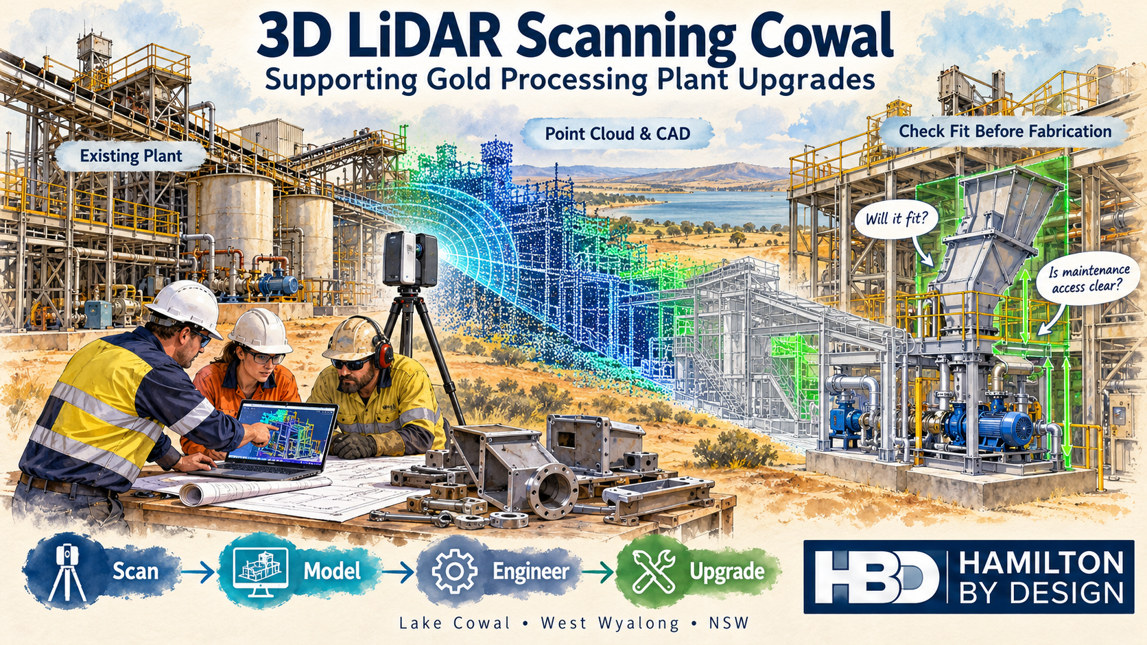
Watercolour illustration of 3D LiDAR scanning for Cowal gold processing plant upgrades, showing a scanner, point cloud, CAD model and Hamilton By Design logo.
Blue 3D LiDAR scanner icon on a tripod with scanning waves

Hamilton By Design offers 3D LiDAR scanning in the Cowal and West Wyalong region to support mechanical engineering, equipment replacement and gold processing plant upgrades. By capturing existing plant geometry before design begins, we help project teams understand available space, assess equipment interfaces and plan modifications with greater confidence.

From a replacement transfer chute to a new pump skid or revised pipe route, reliable information about the existing installation provides a stronger starting point for engineering and fabrication.

Our approach is straightforward: scan โ†’ model โ†’ engineer โ†’ upgrade.

Supporting Gold Processing Projects Near Lake Cowal

Evolution Miningโ€™s Cowal Gold Operations is located near Lake Cowal, approximately 40 kilometres northeast of West Wyalong in New South Wales. The operation includes both open-pit and underground gold mining.

For contractors and engineering teams working on established processing plants, an important challenge is understanding how proposed equipment will fit around the existing installation.

Original drawings provide useful background, but subsequent modifications may have changed pipe routes, equipment positions, access platforms and support arrangements. A new component designed from incomplete information can encounter unexpected clashes during installation.

Hamilton By Design provides scanning and mechanical design services that can support projects in this region, helping teams establish existing conditions before committing to fabrication.

Why Scan Before Designing a Plant Upgrade?

A processing plant upgrade involves more than finding space for a new machine. The design also needs to consider its connections, surrounding equipment, installation route and future maintenance access.

3D LiDAR scanning captures visible surfaces as a point cloud. This creates a spatial record that can be reviewed, measured and used as a reference within compatible CAD software.

Depending on the agreed scope and site access, scanning can help establish:

  • Existing equipment positions and surrounding geometry.
  • Conveyor and transfer chute interfaces.
  • Pipe routes and accessible connection locations.
  • Platform, stair and walkway arrangements.
  • Visible steelwork and support locations.
  • Space around pumps, tanks and mechanical equipment.
  • Potential clashes between proposed and existing installations.
  • Clearances for maintenance and component removal.

Capturing these details early helps the design team identify questions while there is still time to resolve them.

Checking Component Fit Before Fabrication

One of the most useful applications of 3D LiDAR scanning Cowal is checking proposed components against the existing plant.

For example, a replacement chute may need to connect to an existing conveyor discharge, pass through a platform opening and avoid nearby pipework. Each interface affects the final design.

Using a registered point cloud, Hamilton By Design can develop a CAD model of the relevant area and position the proposed component within it.

This allows the project team to review questions such as:

  • Does the component fit within the available space?
  • Do its inlet and outlet positions suit the existing equipment?
  • Are there clashes with steelwork, pipes or platforms?
  • Can personnel reach inspection and maintenance points?
  • Is there enough room to remove liners, motors or other serviceable parts?
  • Does installation require temporary removal of surrounding equipment?

Checking fit in the model helps reduce uncertainty before steel is cut and equipment arrives on site.

Critical interfaces still need an agreed measurement and verification approach, particularly where tight tolerances apply.

Conveyor and Transfer Chute Modifications

Conveyors and transfer chutes bring together several mechanical interfaces within a relatively small area.

A modification may need to accommodate existing conveyor geometry, support steelwork, liner arrangements, access doors and nearby services. Measuring each feature separately can make it difficult to understand their relationship.

3D scanning provides a common spatial reference for reviewing the installation.

Hamilton By Design can use scan data to support:

  • Replacement transfer chute layouts.
  • Conveyor discharge and receiving interfaces.
  • Chute relocation and connection geometry.
  • Wear liner and access door arrangements.
  • Guarding layouts.
  • Maintenance access reviews.
  • General arrangement and fabrication drawings.

The point cloud establishes the visible geometry. Mechanical design then considers operating requirements, material characteristics and the intended function of the equipment.

Pump Skids, Pipework and Equipment Replacement

Replacing a pump or installing a new skid can affect more than its immediate footprint.

Suction and discharge connections, surrounding pipework, motor access, lifting arrangements and maintenance space all influence the layout.

A scan of the installation area can help the design team assess these relationships before selecting a final arrangement.

Typical applications include:

  • Positioning replacement pump skids.
  • Reviewing accessible pipe connection locations.
  • Developing preliminary pipe routes.
  • Checking equipment footprints.
  • Assessing space for valves and maintenance tasks.
  • Identifying clashes with existing services.
  • Preparing coordinated mechanical layouts.

Where flange faces, bolt patterns or other connection details are critical, additional measurements may be required. The capture method should match the tolerance needed for the job.

Scan-to-CAD for Gold Processing Plant Upgrades

A point cloud is a valuable reference, but many projects also need a practical CAD model.

Hamilton By Design can convert selected scan geometry into a model suitable for the agreed design task. This may involve modelling an equipment installation, a transfer area or the surrounding plant layout.

The level of detail should reflect the projectโ€™s purpose.

A preliminary layout may only need equipment envelopes and major obstacles. A replacement component may require more detailed modelling of its connection points and surrounding interfaces.

Depending on the scope, deliverables can include:

  • Registered point clouds in agreed formats, such as E57 or RCP.
  • Selected existing-condition CAD models.
  • Proposed mechanical equipment models.
  • General arrangement drawings.
  • Fabrication drawings for agreed components.
  • STEP, DXF or other compatible CAD files.
  • PDF drawing packs for review and coordination.

Agreeing on the intended use of the data at the start helps ensure that scanning and modelling capture the information the project actually needs.

Planning Work Around Shutdowns

Shutdown installation periods place pressure on maintenance teams, fabricators and contractors. Discovering an unexpected clash during that window can lead to urgent modifications and additional work.

Scanning ahead of a shutdown gives the project team an opportunity to review the installation while design changes are still manageable.

A coordinated model can help teams assess:

  • Component delivery and installation routes.
  • Available space for assembly.
  • Nearby equipment that may restrict access.
  • Interfaces requiring confirmation.
  • Temporary removal requirements.
  • The proposed installation sequence.

Scanning access must be coordinated with site personnel. Equipment isolation, permits, elevated access and operating conditions may affect what can be captured and when.

Early planning helps establish a realistic scope and identify areas that require a separate visit or shutdown access.

Matching Accuracy to the Engineering Task

Different engineering tasks require different levels of measurement detail.

Plant layout scanning can provide a useful record of equipment positions and surrounding geometry. Small machined features, bolt holes and precision mating surfaces may require closer inspection, direct measurement or a suitable metrology scanning method.

For each project, Hamilton By Design considers:

  • The dimensions that matter to the design.
  • The required fit and tolerance.
  • Scanner access and viewing angles.
  • Surface conditions and visibility.
  • Registration requirements.
  • Features requiring supplementary measurement.

LiDAR captures visible surfaces. Hidden connections, internal geometry and obscured areas need further investigation where they affect the design.

The aim is to provide information suitable for the engineering decision being made.

A Practical Workflow from Site Capture to Drawings

Hamilton By Design combines scanning with mechanical engineering and drafting support.

Our workflow starts by defining the proposed modification and identifying its critical interfaces. We then plan the site capture, register the scan data and develop the models needed for review.

Once the proposed arrangement has been assessed and key details confirmed, drawings can be prepared for the agreed fabrication or installation scope.

This connects the site information to a practical outcome: a better-informed design, clearer drawings and fewer unresolved fit-up questions.

Frequently Asked Questions

Can 3D LiDAR scanning help check whether new equipment will fit?

Yes. Scan data can be used as a reference for positioning proposed equipment and checking surrounding clearances. Critical dimensions and interfaces should be verified to suit the required tolerance.

Can you develop fabrication drawings from scan data?

Yes. Hamilton By Design can develop selected CAD models and fabrication drawings from suitable scan data, subject to the agreed scope and confirmation of critical details.

Does the entire processing plant need to be scanned?

No. A targeted scan may be sufficient for a replacement chute, pump installation or local pipework modification. Wider capture can be useful where the project involves several connected areas.

Can scanning take place while the plant is operating?

Some areas may be accessible during operation, subject to site approval and safe access. Other areas may require isolation or shutdown access to capture the necessary geometry.

Can you work with existing point clouds?

Yes. Supplied point clouds can be reviewed for coverage, registration quality and suitability. Additional scanning or measurement may be needed where important interfaces are missing or unclear.

Discuss Your Cowal Plant Upgrade

Planning an equipment replacement, conveyor modification, transfer chute upgrade or pipework installation near Cowal or West Wyalong?

Hamilton By Design can help establish the existing geometry and develop the mechanical models and drawings needed to progress the project.

Send us an outline of the proposed work, site photographs and any available drawings or point cloud data. We can then assess the capture requirements and recommend an appropriate scope.

Contact Hamilton By Design to discuss 3D LiDAR scanning, scan-to-CAD and mechanical engineering support for your Cowal project.


Hamilton By Design logo displayed on a blue tilted rectangle with a grey gradient background

Contact Us – Talk To Us

Name
Would you like us to arrange a phone consultation for you?
Address

Our clients:


3D LiDAR Scanning for Cadia Mining and Processing Plant Projects

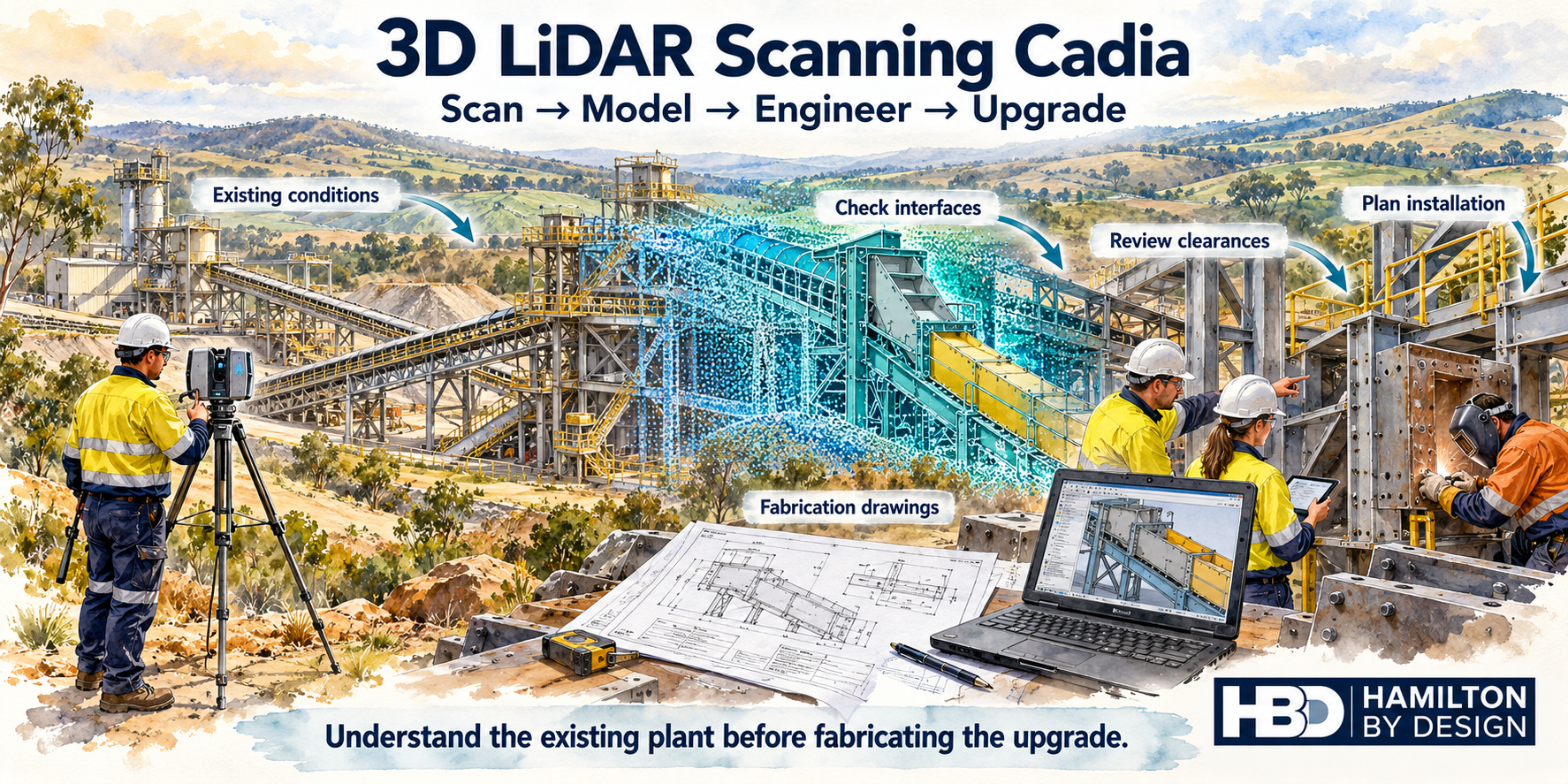
Watercolour illustration of 3D LiDAR scanning for Cadia plant upgrades, showing a scanner, point cloud model, fabrication drawings and engineers checking component fit.
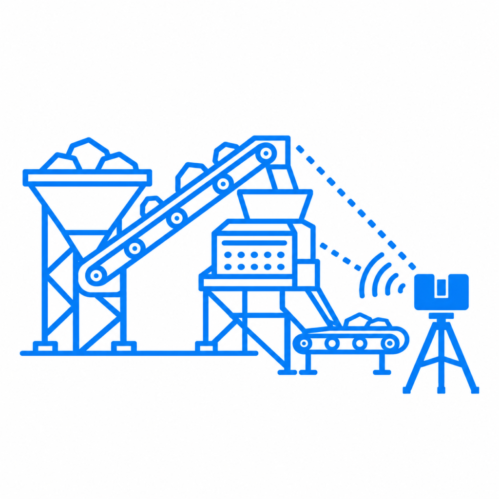
Blue line icon of a tripod-mounted LiDAR scanner surveying a mineral processing plant with a hopper, conveyors and transfer chute.

Hamilton By Design offers 3D LiDAR scanning for Cadia mining and processing plant projects, helping engineers, maintenance teams and fabrication contractors understand existing plant geometry before designing and installing modifications.

From replacement chutes and conveyor interfaces to pump skids and pipework, successful upgrades depend on knowing what is already there. A registered point cloud provides a detailed spatial reference for developing designs, checking clearances and planning installation.

Our approach connects scan โ†’ model โ†’ engineer โ†’ upgrade, turning captured site geometry into practical engineering information.

Supporting Mining Projects Around Cadia and Orange

Cadia is a major gold and copper mining operation owned by Newmont, located approximately 25 kilometres from Orange in Central West NSW. Its scale and industrial setting make existing plant information an important consideration for maintenance and upgrade planning.

For projects in this environment, drawings may need to be checked against equipment that has changed over time. Added pipework, modified supports, replacement machinery and altered access arrangements can affect how a new component fits.

Hamilton By Design can support project teams working in the Cadia and Orange region with site scanning, point cloud processing, mechanical modelling and drawing development. Site work is arranged around the agreed scope, access requirements and operating conditions.

Why Scan Before Designing a Plant Upgrade?

A replacement component may match the original drawing yet still clash with the current installation.

Common sources of uncertainty include:

  • Connection points that differ from the drawings.
  • Pipework or cable trays crossing the proposed installation area.
  • Limited clearance around conveyors and transfer points.
  • Existing steelwork affecting equipment placement.
  • Restricted access for lifting, assembly and maintenance.
  • Changes made during previous shutdowns.

3D LiDAR scanning captures visible surfaces across the work area, allowing the proposed design to be reviewed against its surroundings.

This helps project teams identify potential problems earlier, when changes are generally easier to manage than during fabrication or installation.

3D LiDAR Scanning for Chutes and Conveyor Interfaces

Chute replacements and conveyor modifications require more than the dimensions of the component being replaced. The surrounding arrangement influences the design, installation sequence and future maintenance access.

Scanning can capture:

  • Conveyor positions and transfer point geometry.
  • Existing chute envelopes and accessible connections.
  • Supporting steelwork and nearby platforms.
  • Adjacent services and equipment.
  • Available space for removal and installation.

The point cloud can then support a mechanical model of the proposed arrangement.

For example, a replacement transfer chute can be reviewed against surrounding steelwork, pipework and access platforms before drawings are issued for fabrication. Critical connection dimensions can be identified for additional verification.

Pump Skids, Pipework and Service Modifications

Installing a new pump or changing a pipe route can create challenges in a congested processing plant.

An existing layout may provide enough space for the equipment itself while leaving insufficient room for valves, maintenance activities or removal of major components.

A scan-based model can help assess:

  • Pump skid placement and surrounding clearances.
  • Accessible flange locations and pipe routes.
  • Potential clashes with existing equipment.
  • Space for valve operation and maintenance.
  • Proposed support locations.
  • Installation and component removal paths.

Capturing the surrounding area provides context for these decisions. It helps the designer consider how the equipment will be installed, operated and maintained.

Scan-to-CAD for Mechanical Design and Fabrication

A point cloud becomes more useful when it is connected to the required engineering deliverable.

Hamilton By Design can use registered scan data as a reference for developing CAD models in SolidWorks and AutoCAD. Depending on the project scope, deliverables may include:

  • Registered point clouds.
  • Models of selected existing equipment.
  • Proposed mechanical equipment models.
  • General arrangement drawings.
  • Fabrication and assembly drawings.
  • Interface details and dimensional review information.
  • STEP, DXF or other agreed CAD exchange files.

The level of modelling is selected to suit the task. A layout study may need equipment envelopes and principal interfaces, while a fabrication package requires more detailed geometry and verified connection information.

This keeps the work focused on the decisions the project team needs to make.

Planning Component Fit Before Fabrication

One of the most useful applications of 3D LiDAR scanning at Cadia is checking the proposed component against the existing plant before fabrication begins.

A typical workflow is:

  1. Define the interfaces: Identify connection points, critical dimensions and required clearances.
  2. Capture the work area: Scan the component location and relevant surrounding equipment.
  3. Register and review the data: Check coverage and identify areas requiring further measurement.
  4. Develop the model: Position the proposed component within the existing geometry.
  5. Review fit and access: Assess clashes, assembly requirements and maintenance space.
  6. Prepare the drawings: Document the agreed arrangement and fabrication details.

Scanning supports fit-up planning, but concealed surfaces and fine features may require additional measurement. Bolt holes, machined faces and tight tolerance connections should be assessed individually rather than assumed to be fully defined by a general plant scan.

Supporting Shutdown and Installation Planning

Shutdown work benefits from early decisions about component fit, removal routes and installation access.

A scan-based model can help teams consider questions such as:

  • Can the existing component be removed through the available opening?
  • Will the replacement need to be installed in sections?
  • Does nearby pipework restrict the installation path?
  • Is there enough space to access the connections?
  • Which dimensions need verification before fabrication?

These reviews can support discussions between engineering, maintenance, fabrication and installation teams.

Scanning is most valuable when completed early enough for the findings to influence the design and work plan.

Accuracy Matched to the Engineering Task

The required accuracy should be established before scanning begins.

A broad plant layout study has different requirements from a replacement component with tightly controlled interfaces. Scan coverage, distance, surface condition, visibility and registration all affect the usefulness of the resulting data.

Hamilton By Design works with the project team to identify:

  • The purpose of the scan.
  • Critical interfaces and tolerances.
  • Areas requiring detailed capture.
  • Features needing supplementary measurement.
  • Required file formats and drawing outputs.

This creates a clear basis for the work and helps distinguish captured geometry from dimensions that still need verification.

Frequently Asked Questions

Can scanning help check whether a replacement chute will fit?

Yes. A point cloud can support a model of the replacement chute within the surrounding plant. This helps identify clashes and access constraints. Critical fabrication interfaces may also need direct measurement.

Can you work from an existing point cloud?

Yes. Hamilton By Design can review supplied scan data for modelling and drawing development. Its suitability depends on coverage, registration quality and the detail available around the required interfaces.

Does every scanned item need to be modelled?

No. Modelling can focus on the equipment, surfaces and connections relevant to the project. The remaining point cloud can provide surrounding context.

Can scanning take place while the plant is operating?

This depends on site approval, access and conditions. Moving equipment, dust, vibration and obstructed views may limit capture. Some areas may require isolation or shutdown access.

Can you provide drawings as well as scanning?

Yes. The scope can include point cloud processing, mechanical modelling, general arrangements and fabrication drawings, with deliverables agreed before work begins.

Discuss Your Cadia Scanning Project

Planning a chute replacement, conveyor modification, pump installation or processing plant upgrade near Cadia?

Contact Hamilton By Design to discuss 3D LiDAR scanning, scan-to-CAD modelling and mechanical design support.

Send photographs, existing drawings and a brief description of the proposed work so we can identify the required scan coverage, critical interfaces and suitable deliverables.

Capture the existing plant. Check the proposed fit. Develop the upgrade with better information.


Hamilton By Design logo displayed on a blue tilted rectangle with a grey gradient background

Contact Us – Talk To Us

Name
Would you like us to arrange a phone consultation for you?
Address

Our clients:


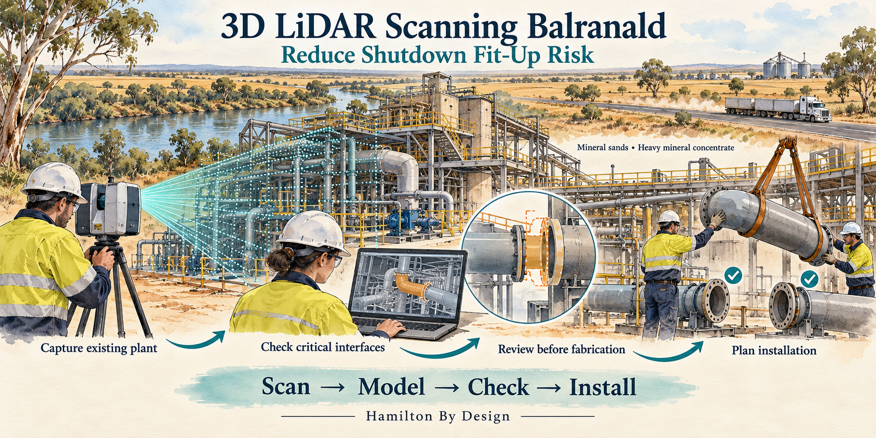
3D LiDAR Scanning Balranald NSW โ€“ Reduce Shutdown Fit-Up Risk

Watercolour illustration of 3D LiDAR scanning at a mineral processing plant in Balranald NSW, showing component checks and shutdown installation planning.
Blue 3D LiDAR scanner icon on a tripod with scanning waves

Check how replacement components connect to existing plant before fabrication and installation.

Hamilton By Design provides 3D LiDAR scanning, scan-to-CAD modelling and mechanical design services for mineral processing facilities in Balranald and south-western NSW.

For maintenance teams, engineering contractors and fabricators, the objective is practical: understand the installed geometry, check critical interfaces and identify clashes before equipment arrives on site.

Whether replacing a chute, modifying slurry pipework or installing a new pump skid, early scanning can help reduce the risk of components requiring unexpected modification during a shutdown.

Supporting Balranaldโ€™s Mineral Sands Industry

Ilukaโ€™s Balranald operation is located approximately 12 kilometres northwest of Balranald in south-western NSW. The mineral sands deposits contain rutile, zircon and rare earth-bearing minerals, with an on-site concentrating plant producing heavy mineral concentrate for further processing.

Iluka reports that mining and processing of run-of-mine ore commenced in January 2026.

For mineral sands and heavy mineral concentrate facilities, equipment modifications need to account for the plant as it exists today. Pipework, supports, access platforms and neighbouring equipment can all influence whether a replacement assembly fits.

Hamilton By Design offers scanning and mechanical design support for operators and contractors undertaking this type of work in the Balranald region.

Will the New Component Fit the Existing Plant?

A replacement component may match its drawing yet still encounter problems during installation.

Existing equipment may have been modified, supports may sit differently from their original design positions, or surrounding services may restrict access. Older drawings may also omit changes made during previous maintenance work.

Common fit-up problems include:

  • Pipe flanges that do not align with replacement spools.
  • Chute connections that differ from the original drawings.
  • Pump skids that conflict with existing pipework or supports.
  • Brackets and mounting plates positioned differently from the design.
  • Guards that interfere with nearby equipment.
  • Components that fit their final position but cannot pass through the installation route.

3D LiDAR scanning captures visible plant geometry so these interfaces can be reviewed before fabrication.

The aim is to resolve fit-up questions while there is time to change the design.

Capture the Plant Before the Shutdown

Scanning ahead of a planned shutdown creates a spatial reference for engineering and fabrication.

The survey can focus on the equipment being replaced, its connection points and the surrounding area needed for installation and maintenance.

Depending on the project, this may include:

  • Equipment positions and external geometry.
  • Pipe routes and accessible connection points.
  • Chute inlet and outlet interfaces.
  • Existing frames and support arrangements.
  • Platforms, stairs, handrails and access restrictions.
  • Nearby equipment and services.
  • Available space for removal and installation.

Access, visibility and the required tolerances guide the scanning plan. Where operating equipment obscures critical features, additional capture may be needed during an agreed isolation or access window.

Check New Equipment Against the Point Cloud

A registered point cloud provides a three-dimensional record of the scanned area. Proposed equipment models can then be positioned within that record to assess how they connect to the existing plant.

Hamilton By Design can use this process to review:

  • Replacement chute geometry and connection locations.
  • Slurry and process pipework routes.
  • Pump skid positions and service connections.
  • Equipment support interfaces.
  • Guarding arrangements.
  • Maintenance clearances.
  • Installation envelopes and potential clashes.

For example, a replacement pipe spool can be modelled against the surveyed route, with its end connections and nearby obstructions reviewed before drawings are released.

This gives engineers, fabricators and installation teams a common reference for discussing changes.

LiDAR Scanning and Critical Fit-Up Measurements

The measurement method needs to suit the connection being checked.

LiDAR scanning is useful for capturing plant layouts, equipment envelopes and surrounding geometry. Close-tolerance features such as small bolt holes, machined faces and shaft interfaces may require supplementary measurement or higher-resolution component scanning.

Hamilton By Design can combine plant scanning with targeted checks of critical interfaces.

Before mobilisation, we establish:

  • Which components must connect.
  • The required fit-up tolerances.
  • Which surfaces and features are accessible.
  • Where supplementary measurements are needed.
  • Which dimensions require verification before fabrication.

This approach makes the scan useful for the installation decision. A clash-free model alone does not establish that every connection meets its required tolerance.

Mechanical Design for Mineral Processing Modifications

Capturing geometry is the first step. Turning it into usable engineering information helps the project move towards fabrication and installation.

Hamilton By Design can support:

Chute replacements and modifications
Model existing interfaces and develop replacement geometry around available space, connection points and maintenance access.

Pipework and spool arrangements
Capture existing routes and support positions to assist with replacement spools, rerouting and equipment connections.

Pump skids and equipment layouts
Review proposed equipment against the installed plant, including surrounding services and maintenance space.

Guarding and access arrangements
Develop geometry around existing equipment while considering inspection, maintenance and removal requirements.

Reverse engineering
Create CAD models of accessible components where suitable drawings are unavailable, with critical dimensions checked using an appropriate measurement method.

The scope can range from a focused interface survey to a broader scan-to-CAD and mechanical design package.

A Practical Workflow for Shutdown Planning

1. Define the fit-up problem

Identify the replacement equipment, connection points, shutdown constraints and required deliverables.

2. Capture the existing installation

Scan the relevant area and complete agreed supplementary measurements.

3. Build the spatial reference

Register the scan data and prepare the point cloud for engineering review.

4. Model and review the proposed components

Check interfaces,


Hamilton By Design logo displayed on a blue tilted rectangle with a grey gradient background

Contact Us – Talk To Us

Name
Would you like us to arrange a phone consultation for you?
Address

Our clients:

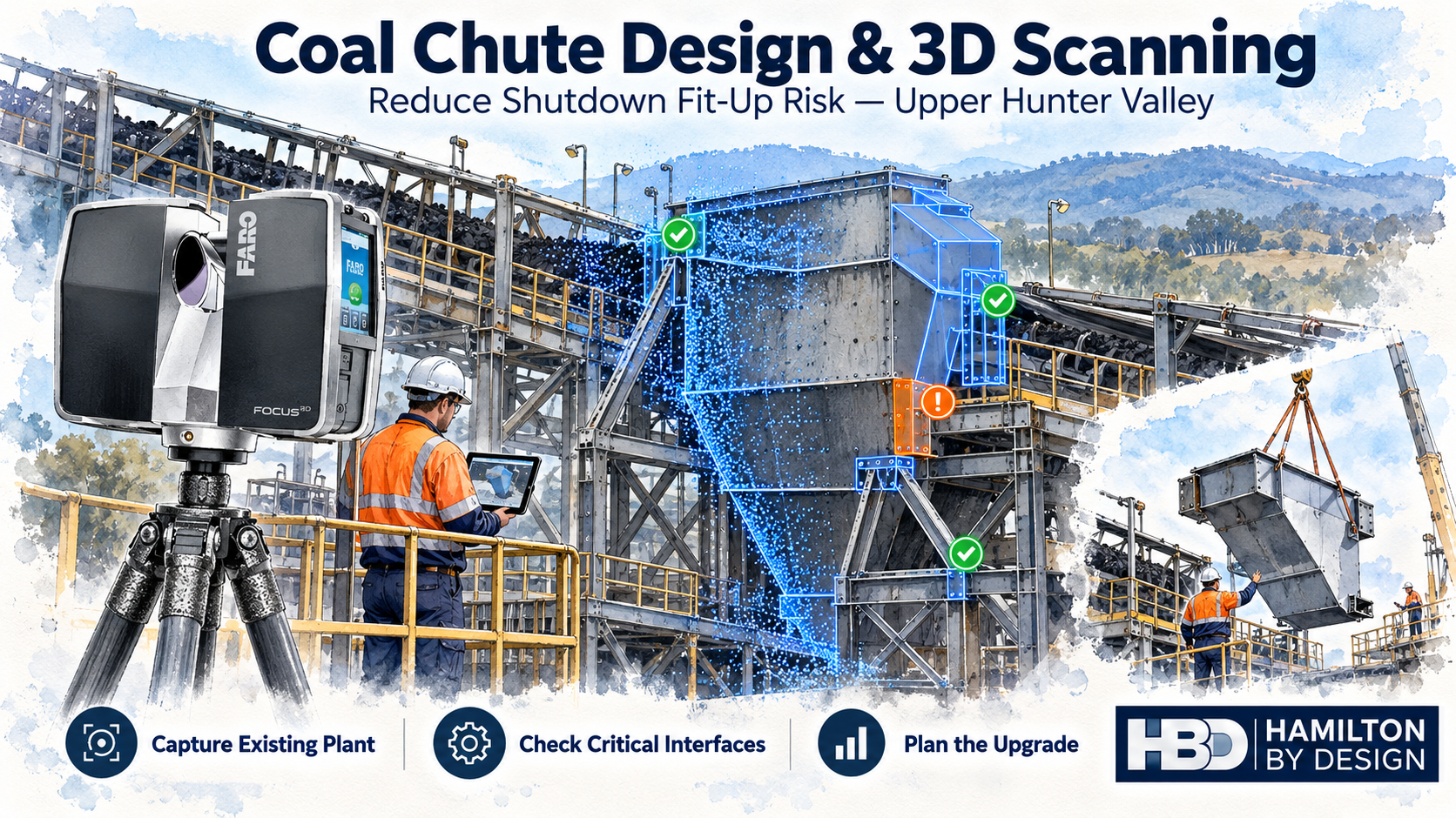
Coal Chute Design Upper Hunter Valley: Reduce Shutdown Fit-Up Risk with 3D Scanning

FARO laser scanner capturing a coal transfer chute in the Upper Hunter Valley, with point-cloud overlays highlighting upgrade interfaces.

Reduce Shutdown Upgrade Fit-Up Risk with 3D Laser Scanning for Your Coal Chute

Blue 3D LiDAR scanner icon on a tripod with scanning waves

A replacement coal chute can be fabricated exactly to the drawing and still fail to fit the plant.

Existing supports may have moved. Flanges may have been modified. Additional bracing, pipework or cable trays may occupy the installation space. Older drawings may no longer represent the equipment installed on site.

When these differences are discovered during a shutdown, the consequences can include field cutting, additional welding, revised lifting arrangements and delays to returning the plant to service.

Hamilton By Design provides coal chute design, 3D scanning and mechanical engineering support for projects across Muswellbrook, Singleton and the Upper Hunter Valley. We capture existing plant geometry, develop the proposed chute within its surrounding environment and check critical interfaces before fabrication.

The objective is practical: identify fit-up problems early, when there is still time to resolve them.

Why Coal Chute Upgrades Need Reliable Site Information

Coal chutes connect equipment within a larger materials handling system. Their design must consider the relationship between the incoming conveyor, discharge point, chute supports and receiving equipment.

A replacement chute may need to connect with:

  • Existing discharge hoods and head pulley arrangements.
  • Receiving conveyors and loading zones.
  • Structural supports and mounting plates.
  • Skirting and dust containment systems.
  • Platforms, walkways and guarding.
  • Inspection doors and maintenance access.
  • Adjacent pipework, cable trays and services.

Measuring only the chute opening can leave important installation constraints unresolved.

A chute might fit between its connection points but clash with nearby steelwork. A liner access door might open directly into a handrail. A larger replacement assembly might be difficult to move through the available installation route.

Coal chute design needs to consider both the equipment and the space required to install, operate and maintain it.

Use 3D Scanning Before Finalising the Chute Design

3D laser scanning captures the visible geometry of the existing chute and surrounding plant from multiple positions.

The scans are registered into a point cloud that can be used for measurement, modelling and engineering review.

For a coal chute upgrade, the capture scope can include:

  • Chute inlet and outlet positions.
  • Visible flange and support geometry.
  • Conveyor alignment and surrounding equipment.
  • Structural steelwork and bracing.
  • Access platforms, stairs and handrails.
  • Services near the proposed modification.
  • Available space for removal and installation.

This provides a broader understanding of the existing installation than a small set of isolated measurements.

The proposed chute model can then be positioned within the point cloud to assess how it relates to the actual plant.

For related regional services, see Mine Conveyor Gallery Scanning Hunter Valley NSW.

Check Critical Interfaces Before Fabrication

Fit-up risk often concentrates at the points where new equipment connects with existing plant.

For coal chutes, these may include mounting faces, support brackets, flange connections and the relationship between the chute outlet and receiving conveyor.

Hamilton By Design uses the scan and engineering model to review these interfaces before drawings are released for fabrication.

Depending on the project, the review can address:

  • Connection positions and orientations.
  • Support spacing and elevations.
  • Clearance around the chute body.
  • Access to bolts and installation tools.
  • Space for liners and inspection doors.
  • Interfaces with existing guarding.
  • Allowance for fabrication and installation tolerances.

Critical dimensions require a measurement method suited to their tolerance. Small bolt holes, concealed faces and close-tolerance connections may need direct measurement or supplementary scanning.

The required accuracy should be agreed at the start of the project, with any inaccessible or uncertain interfaces clearly identified.

Coal Chute Design Must Also Consider Material Flow

A chute that fits the plant still needs to handle the coal effectively.

Coal chute design should consider the operating conditions supplied by the client, including:

  • Required throughput.
  • Incoming belt speed and material trajectory.
  • Coal lump size and fines content.
  • Bulk density and moisture variation.
  • Available transfer height.
  • Receiving conveyor arrangement.
  • Existing wear, blockage or spillage problems.

These inputs help guide the chute geometry, liner arrangement, access requirements and transfer configuration.

Where material behaviour is complex, specialist material-flow assessment or Discrete Element Method modelling may be appropriate. The level of analysis should match the problem and the consequences of poor performance.

3D scanning establishes the existing geometry. Engineering assessment determines how the proposed coal chute should function within that geometry.

Design for Maintenance and Liner Replacement

Maintenance access should be considered while developing the chute.

A compact design may appear suitable in a general arrangement but become difficult to maintain once installed. Wear liners may be obstructed by supports, fasteners may be inaccessible, or removable sections may lack a practical handling route.

Depending on the scope, chute design can consider:

  • Replaceable wear liner sections.
  • Access to liner fasteners.
  • Inspection and clean-out openings.
  • Removable panels and chute sections.
  • Space for maintenance tools.
  • Component handling and removal paths.

Lifting provisions and structural support changes require appropriate engineering assessment.

Considering these requirements before fabrication helps maintenance teams understand how the chute will be serviced throughout its operating life.

Plan the Shutdown Around the Proposed Installation

A digital model can support discussions between the engineering team, fabricator, maintenance personnel and shutdown planner.

Together, they can review how the existing chute will be removed and how the replacement will reach its final position.

Questions to resolve include:

  • Can the chute be installed as one assembly?
  • Does it need to be divided into smaller sections?
  • Which existing items need temporary removal?
  • Are the proposed connections accessible?
  • Is enough space available to manoeuvre the assembly?
  • What work can be completed before the shutdown?

Resolving these questions early helps define the fabrication package and installation scope.

The scan supports this planning by showing the surrounding geometry. Final lifting methods, temporary works and site execution arrangements still need their own assessment.

From Site Capture to Coal Chute Fabrication Drawings

Hamilton By Design can develop a staged workflow suited to the project.

1. Define the Upgrade

Confirm the reason for the modification, operating requirements, existing problems, shutdown timing and required deliverables.

2. Capture the Existing Plant

Complete 3D scanning and supplementary measurements of the chute, supports, conveyors and relevant surrounding infrastructure.

Internal capture depends on safe access, isolation and visibility. Hidden or obstructed surfaces must be addressed separately.

3. Develop the Chute Design

Model the proposed chute against the captured plant, considering interfaces, material flow, liners, maintenance access and installation constraints.

4. Review the Arrangement

Review the design with the client and relevant site personnel. Resolve outstanding measurements and interface questions before fabrication release.

5. Prepare the Documentation

Depending on the agreed scope, deliverables can include:

  • Registered point clouds.
  • Existing-condition and proposed CAD models.
  • General arrangement drawings.
  • Chute fabrication and assembly drawings.
  • Wear liner layouts.
  • Interface details and installation information.
  • STEP, DWG, DXF and PDF files.

Learn more about our Mechanical Engineering Services in Muswellbrook.

Supporting Coal Chute Upgrades Across the Upper Hunter

Hamilton By Design supports coal chute and materials handling projects across Muswellbrook, Singleton, Denman and surrounding Upper Hunter mining areas, together with the wider Hunter Valley.

Typical applications include transfer chute replacements, worn chute reconstruction, conveyor modifications, liner upgrades and brownfield CHPP projects.

Our Hunter Valley Mining Engineering and 3D Laser Scanning Services provide broader regional support.

Frequently Asked Questions

Can 3D scanning reduce coal chute fit-up risk?

Yes. It can help identify differences between existing drawings and visible site conditions, allowing proposed equipment to be reviewed before fabrication. It reduces uncertainty but does not guarantee installation fit.

Do we need scanning if we already have drawings?

Existing drawings are useful starting information. Scanning is particularly valuable where the plant has been modified, dimensions are uncertain or the replacement chute must fit within congested infrastructure.

Can you scan inside a coal chute?

Internal scanning may be possible where the chute is safely isolated, accessible and sufficiently clear. Access conditions and site requirements must be assessed before capture.

Can the existing chute be reverse engineered?

Visible and accessible geometry can support CAD reconstruction. Worn or damaged geometry must be assessed so that the new design reflects the intended function rather than simply copying deterioration.

When should the scan be completed?

Ideally, before detailed design and fabrication. This gives the project team time to resolve interface issues and prepare the upgrade before the shutdown.

Discuss Your Coal Chute Upgrade

If you are planning a coal chute replacement or conveyor transfer upgrade in the Upper Hunter Valley, involve Hamilton By Design before fabrication begins.

We can help establish the existing geometry, develop the chute design and review the interfaces that influence shutdown fit-up.

Capture the existing plant. Check the proposed chute. Prepare the upgrade before the shutdown.

Contact Hamilton By Design to discuss your chute design and 3D scanning requirements.


Hamilton By Design logo displayed on a blue tilted rectangle with a grey gradient background

Contact Us – Talk To Us

Name
Would you like us to arrange a phone consultation for you?
Address

Our clients:

3D LiDAR Scanning Homes in Double Bay, Sydney NSW

Watercolour of a LiDAR scanner capturing a Double Bay home, with a blue point-cloud overlay, harbour views and Hamilton By Design logo.

Understand your home before planning changes

Blue outline icon of a tripod-mounted LiDAR scanner scanning a residential house.

Planning a renovation, extension or internal redesign in Double Bay? Before preparing detailed drawings, it helps to establish how your home is built today.

Original plans may be missing or may no longer reflect previous alterations. Walls, openings, floor levels and ceiling heights can differ from what appears on an old drawing.

Hamilton By Design provides 3D LiDAR scanning for homes in Double Bay, Sydney NSW, capturing visible, accessible building surfaces to create a measured digital record. This information helps architects, building designers, engineers and builders develop proposed changes around existing conditions.

Whether you are opening up a living area, replacing a staircase or extending your home, scanning provides a practical starting point for design.

What is residential 3D LiDAR scanning?

A terrestrial LiDAR scanner measures building surfaces from a series of stationary positions. Individual scans are combined into a registered point cloud, representing the geometry captured throughout the property.

Unlike a collection of separate room measurements, a coordinated point cloud allows the project team to review adjoining spaces together. This helps explain how rooms, openings and levels relate to one another.

Depending on access and the agreed scope, residential scanning can capture:

  • Internal walls, floors and ceilings.
  • Door and window openings.
  • Stairs, landings and surrounding spaces.
  • Visible beams, columns and bulkheads.
  • External faรงades and accessible roof geometry.
  • Balconies, terraces and courtyards.
  • Visible services and equipment.
  • Areas where proposed construction will connect to the existing home.

The dataset can then support selected existing-condition drawings or 3D CAD modelling where these outputs are commissioned.

Why scan a Double Bay home before renovating?

A renovation often changes how several spaces work together. Removing a wall, enlarging an opening or changing a staircase can affect adjoining rooms, circulation and the position of new fixtures.

Understanding these relationships early gives the designer more useful information when assessing options.

Replace assumptions with measured geometry

A room that appears rectangular may have walls that are slightly out of square. A ceiling may change height around a bulkhead. An opening may be positioned differently from the original plans.

These details can affect cabinetry, glazing, stairs and other components that must fit the existing building.

Scanning helps document accessible geometry so the design team can identify where closer checks are needed.

Review adjoining rooms together

For a kitchen and living room renovation, individual room dimensions may not explain the whole layout.

A registered point cloud can show the relationship between the kitchen, hallway, living area and outdoor opening. This helps the designer assess proposed layouts within the wider space.

Keep a record before demolition

Once walls, ceilings or fittings are removed, their original positions may be difficult to reconstruct.

A pre-renovation scan preserves a measured record of the surfaces captured. The project team can return to that information when reviewing an original opening, room arrangement or connection detail.

Applications for home scanning in Double Bay

Kitchen and living area alterations

Changing the kitchen layout or creating an open living area requires an understanding of existing wall positions, openings, ceiling geometry and floor levels.

Scanning can provide the spatial reference for developing the proposed layout. Structural decisions about removing walls require assessment by the appropriate engineer.

For custom cabinetry, critical installation dimensions should be checked to the tolerances required by the supplier.

House extensions

An extension must connect with the home already on site.

Scanning the adjoining rooms and relevant external surfaces helps document the geometry around floor transitions, doorways, eaves and accessible roof junctions.

This information supports the design of the connection between existing and proposed construction.

Staircase replacements

A new staircase needs to work within the available opening and connect with actual floor levels.

Capturing the stairwell, adjoining landings, nearby doors and ceiling surfaces helps the project team review the available space. Stair design, structural adequacy and compliance remain part of the relevant professional assessment.

Glazing, doors and joinery

Large windows, sliding doors and fitted joinery can depend on the relationship between several existing surfaces.

Scan data can support coordination and modelling of those interfaces. Where components require a close fit, targeted dimensional verification should form part of the agreed workflow.

Balconies and terraces

A renovation may involve changes to a balcony, terrace or the opening between indoor and outdoor areas.

Scanning accessible surfaces can help document thresholds, edges, nearby walls and level changes. Waterproofing, drainage, structural design and other specialist requirements need separate assessment.

Building services alterations

Visible pipework, ductwork and equipment can be captured where accessible. This can help coordinate proposed changes around existing services.

LiDAR does not reveal pipes, wiring or framing concealed behind walls and ceilings.

A practical example: redesigning a kitchen and terrace connection

Imagine renovating a Double Bay home to create a larger kitchen and improve access to an outdoor terrace.

The proposal includes new cabinetry, a wider glazed opening and a revised internal layout. The designer needs to understand how the kitchen floor, ceiling, adjoining walls and terrace threshold relate to one another.

A targeted scan can capture these accessible areas together before the design is finalised.

The project team can then use the point cloud and any commissioned drawings to review the layout and identify interfaces needing further investigation. Before ordering glazing or cabinetry, the relevant supplier can verify the critical dimensions.

This approach helps bring measurement questions into the design stage, when adjustments are easier to make.

From a home scan to useful project information

The right deliverable depends on who will use the data and what they need to do with it.

Some designers can work directly with point clouds. Others require selected drawings or a model of the building areas being changed.

Hamilton By Design can scope the following outputs around your project.

Registered point cloud

A coordinated dataset representing the captured surfaces, supplied in an agreed format compatible with the project teamโ€™s software.

Existing-condition drawings

Selected floor plans, elevations or sections prepared from the scan data where included in the quotation.

3D CAD models

Models of agreed building geometry to support layout review, communication and coordination.

Selected interface documentation

Drawings or modelled geometry focused on particular openings, stairs or connections relevant to the proposed work.

Scanning, drawing preparation and modelling are defined in the agreed scope. This makes clear which areas will be captured and what information will be supplied.

How we plan residential scanning

1. Understand the proposed changes

Share your property location, available plans and a description of the work. Your architect or designerโ€™s requirements help determine the capture areas and outputs.

2. Identify important interfaces

We discuss the dimensions and connections that matter most to the project, including any fabrication requirements or restricted areas.

3. Arrange access

Clear sight lines improve capture. Furniture, stored items and vegetation may obscure surfaces, so preparation is considered before the visit.

4. Capture the agreed areas

The scanner is positioned at multiple locations to collect overlapping views of accessible building surfaces.

5. Process and prepare the deliverables

The scans are registered and reviewed before the agreed point cloud, drawings or models are prepared. Relevant coverage limitations are communicated to the project team.

When should you scan your home?

For most renovation and extension projects, scanning is useful before detailed design is finalised and before demolition starts.

Capturing early allows the existing geometry to inform the proposal.

Further scanning may be appropriate after demolition exposes additional surfaces, before installing selected components or at completion. Each visit should have a defined purpose and an agreed scope.

Frequently asked questions

Can you scan an occupied home in Double Bay?

Yes, subject to suitable access arrangements. Furniture and personal items may obstruct surfaces, so we discuss the areas that need clear views before scanning.

Can I arrange scanning if I have no existing plans?

Yes. Scanning can provide measured information from which selected existing-condition drawings can be prepared. Those drawings need to be included in the agreed scope.

Do I need to scan the entire property?

Not necessarily. A focused renovation may only require the affected rooms and adjoining interfaces. A substantial extension or redesign may benefit from broader coverage.

How accurate is 3D LiDAR scanning?

Accuracy depends on the equipment, site conditions, scan positions, registration and the feature being measured.

The intended use and required tolerances should be discussed before capture. Critical fabrication dimensions may require additional verification.

Can the scanner see through walls?

No. LiDAR captures surfaces visible to the scanner. Concealed framing, wiring, pipes and other hidden features require access or a separate investigation method.

Will I automatically receive floor plans?

Floor plans, elevations, sections and models are additional outputs that must be included in the agreed scope. A point cloud is the underlying measured dataset.

Can my architect use the scan?

Yes, provided the deliverables suit their software and workflow. We confirm the required formats and outputs before work begins.

Does scanning confirm whether a wall can be removed?

No. Scanning can document visible wall positions and surrounding geometry. Determining whether a wall is load-bearing requires assessment by an appropriately qualified professional.

Does residential scanning replace a boundary survey?

No. Capturing building geometry does not establish legal property boundaries. Boundary and cadastral survey requirements should be addressed by an appropriately qualified surveyor.

How much does scanning a home in Double Bay cost?

The price depends on property size, capture areas, access, processing and the required drawings or models. Available plans, photographs and a project brief help establish an appropriate quotation.

Explore our nearby residential scanning posts:

Planning changes to your Double Bay home?

Give your project team a measured starting point before committing to detailed design.

Contact Hamilton By Design to discuss 3D LiDAR scanning for your home in Double Bay, Sydney NSW.

Send your property location, available drawings and a brief description of the proposed changes so we can define the capture areas and deliverables your project needs.


Hamilton By Design logo displayed on a blue tilted rectangle with a grey gradient background

Contact Us – Talk To Us

Name
Would you like us to arrange a phone consultation for you?
Address

Our clients: