Mechanical Engineering | 3D Scanning | 3D Modelling
Tag: structural-drafting
Hamilton By Design provides structural drafting, 3D CAD modelling and detailed drawing support for industrial facilities and brownfield plant projects.
Our role is to convert approved structural engineering designs, calculations and mark-ups into coordinated models and practical drawings for review, fabrication and installation. Hamilton By Design does not provide structural engineering certification.
Structural drafting services can support equipment frames, platforms, walkways, stairs, gantries, supports, access structures and other fabricated steelwork. Depending on the agreed scope, deliverables can include:
Existing-condition steelwork models
General arrangement drawings
Plans, elevations and sections
Member and assembly drawings
Engineer-approved connection details
Fabrication and installation drawings
Material lists and parts schedules
DXF cutting profiles
Revision-controlled drawing packages
Where existing drawings are incomplete or no longer represent site conditions, 3D LiDAR scanning can capture installed steelwork, equipment interfaces and surrounding plant. The registered point cloud provides a reliable reference for modelling proposed modifications and identifying potential clashes.
Structural member sizes, loads, connections and design details must be supplied or approved by the project’s structural engineer. Structural calculations, connection design, certification and final approval remain the responsibility of an appropriately qualified and registered structural engineer.
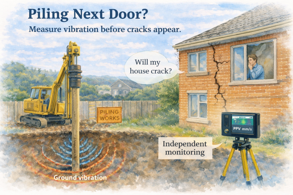
Construction in Australia is getting closer to existing homes than ever before. Subdivisions, duplex developments, basement garages and boundary wall construction now routinely occur only metres from established houses.
One of the most misunderstood risks during nearby construction is ground vibration — particularly from piling, sheet piling, rock breaking and compaction equipment.
Most homeowners only notice the issue once cracks appear.
By that point, proving the cause becomes significantly harder.
What Is Actually Happening During Piling?
When a neighbouring builder installs piles, the ground does not simply “shake” — it transmits energy waves through the soil. These waves travel through the foundation system of your home and can interact with the structure in very specific ways.
Depending on soil type and building construction, vibration can:
Amplify inside brick veneer cavities
Transfer through footings into slab edges
Excite steel lintels above windows
Cause differential movement between materials
Open previously dormant shrinkage cracks
Break brittle materials like grout and plasterboard joints
Many owners describe it as feeling like a truck hitting the house repeatedly — and structurally, that is not far from reality.
The Critical Problem — Evidence
Here is the reality:
If you do not measure vibration before damage occurs, proving responsibility later becomes extremely difficult.
Once construction finishes:
The vibration source is gone
Monitoring cannot be retroactively installed
Engineers must rely on assumptions
Insurance claims are often rejected
Builders argue pre-existing damage
This is why most vibration disputes fail — not because damage didn’t happen, but because it wasn’t recorded at the time.
Why Cracks Appear Days or Weeks Later
Damage does not always occur instantly.
Vibration commonly causes:
Micro-movement in mortar joints
Loosening of interfaces between materials
Progressive settlement in reactive soils
Then later:
A hot day
Rain event
Door closing
Minor thermal expansion
…and the crack becomes visible.
The construction activity triggered the mechanism — but the visible damage appears later.
Without monitoring, causation becomes nearly impossible to demonstrate.
Australian Standards — The Legal Threshold
Australian and international building damage criteria are based on Peak Particle Velocity (PPV), not how strong vibration feels.
Typical residential guidance limits:
Frequency
Cosmetic Damage Threshold
< 10 Hz
~5 mm/s
10–50 Hz
5–15 mm/s
> 50 Hz
up to 20 mm/s
Important:
Human perception is NOT a reliable indicator of structural damage risk.
Some damaging vibrations feel mild. Some strong sensations cause no damage.
Only instrumentation determines the difference.
What You Should Do — Before Work Starts
If you have received a notice of:
Piling
Rock breaking
Basement excavation
Sheet piling
Compaction works
Demolition close to boundary
You should arrange:
1. Pre-Construction Condition Survey
Photographic and measured documentation of existing condition.
2. Vibration Monitoring Installation
Sensors installed before the first machine arrives.
3. Continuous Logging During Construction
Provides legal evidence if thresholds are exceeded.
Why Timing Matters
The most valuable data occurs during the first day of piling.
After that:
Cracks may already initiate
You have no baseline
Arguments become opinion-based
Early measurement protects everyone — homeowner and builder alike.
Who Is Responsible?
In Australia, responsibility is generally determined by measurable physical impact, not perception.
Courts consistently require:
Recorded vibration data
Engineering interpretation
Demonstrated building response
Without measurement, claims rely on visual opinion — which rarely succeeds.
Peace of Mind Is the Real Outcome
Many monitored projects show vibration stays within acceptable limits. In those cases, owners gain certainty their home is safe.
Monitoring is not about creating conflict — it is about removing uncertainty.
We Travel Australia-Wide
Hamilton By Design provides independent vibration recording across Australia, including regional and remote locations.
We install monitoring equipment prior to construction and provide documented records suitable for engineering or legal use if required.
If Construction Is About To Start Next Door
Do not wait for cracks.
Once visible damage appears, the opportunity to capture critical evidence has often already passed.
A Practical Engineering Guide to Correct Fastener Selection in Australia
Bolts are one of the most common engineered components on any project — and also one of the most misunderstood.
In drawings they appear as a simple note: M16 – 8.8 – GALV
Yet behind that small call-out sits structural capacity, fatigue life, corrosion resistance, inspection compliance, and legal responsibility.
Many engineering failures do not occur because a beam was undersized or a calculation was incorrect. They occur because the wrong fastener type was selected for the application.
This article explains:
Bolt and nut property classes
Where each class should be used
Carbon steel vs stainless steel
Coatings and environment suitability
Structural vs mechanical bolting
Australian Standards governing fasteners
How to review and challenge incorrect selections — especially when mentoring graduate engineers
1. The Three Different Worlds of Bolting
Most confusion exists because people think a bolt is simply a stronger or weaker version of the same item.
In reality, bolts exist in three different engineering systems:
System
Purpose
Governing Standards
General Mechanical Fastening
Holding components together
ISO / AS 1110 / AS 4291
Structural Bolting
Load transfer between steel members
AS/NZS 1252 / AS 4100
Corrosion Resistant Fastening
Survive environment
Stainless / coatings standards
Using a bolt from the wrong system often creates hidden failures.
2. Bolt Property Classes (Metric)
Metric bolts are marked with numbers such as 4.6, 8.8, 10.9, 12.9
These numbers define material strength.
What the Numbers Mean
First number → Ultimate tensile strength (×100 MPa) Second number → Yield ratio
Mechanical Engineering Support Benalla | Manufacturing & Industrial
Practical engineering for real factories, real equipment, real deadlines
Benalla and the North East Victorian region are built on strong manufacturing—electrical equipment, heavy industry, fabrication, food processing, and specialist production. Mechanical engineers working in these environments need support that understands uptime, safety, compliance, and getting equipment back into service quickly.
Hamilton By Design provides hands-on mechanical engineering services that help manufacturers move from site reality to engineering-ready solutions—without disrupting production.
Who we work with
We support mechanical engineers, maintenance teams, project managers, and workshop leaders across:
Electrical and industrial equipment manufacturing
Process and production facilities
Fabrication workshops and OEM suppliers
Maintenance and reliability teams
Capital upgrade and shutdown projects
Our role is to strengthen your in-house capability with accurate site information, practical design support, and clear engineering deliverables.
Our services
Site verification & as-built capture
Decisions are only as good as the information behind them. We help confirm existing conditions before designs are locked in.
Existing plant and equipment verification
Field measurement and dimensional checks
Brownfield interface confirmation
Layout validation before fabrication
3D laser scanning for manufacturing sites
Modern manufacturing upgrades demand accurate spatial data. We capture and deliver point clouds tailored for engineering workflows.
Rapid on-site data capture
Registered point cloud deliverables
Support for upgrades, relocations, and new equipment installs
Clash identification before shutdowns
Mechanical layout & modification support
Practical engineering to make changes fit the real world.
Equipment arrangement and access reviews
Interface coordination with structures and services
Design checks against site constraints
Fabrication and installation support
Reliability & maintenance engineering
Helping teams reduce downtime and improve maintainability.
Maintenance access optimisation
Equipment changeover planning
Practical improvement recommendations
Support for maintenance documentation
Manufacturing documentation
Clear, structured information that workshop and site teams can actually use.
Engineering-ready drawing packages
Asset and modification records
Handover documentation
Fabrication support information
Why manufacturing teams choose us
Engineer-led, site-first approach – we design around how your plant really operates
Production-aware – focused on minimal disruption and practical outcomes
Cross-discipline thinking – mechanical, structural and fabrication interfaces
Deliverables that work on the workshop floor – not just in the office
Typical projects in Benalla
Equipment upgrades and replacements
New machine installations into existing lines
Factory relocations and layout changes
Shutdown measurement and documentation
Access and maintainability improvements
Reverse engineering of legacy equipment
How we engage
Initial discussion – understand your equipment, constraints, and timeline
Plan the site approach – access, safety, and production considerations
On-site capture & verification
Delivery of practical engineering outputs ready for your workflow
Contact
If you’re a mechanical engineer or manufacturer in Benalla needing practical engineering support, we can help bridge the gap between site and design.
Hamilton By Design Co. Servicing Benalla & Northeast Victoria
Engineering Lessons from Recent Media: Foundations & Process First
A recent Tasmanian news story reported on a homeowner receiving a substantial payout after major renovations led to cracking in their house. The coverage in The Mercury described how the problems were linked to inadequate consideration of existing footings and ground conditions during the design of a second-storey extension:
Rather than revisiting who was right or wrong, the reporting offers a constructive opportunity to reflect on how everyday engineering processes can be improved—especially on renovation and brownfield projects where information is incomplete.
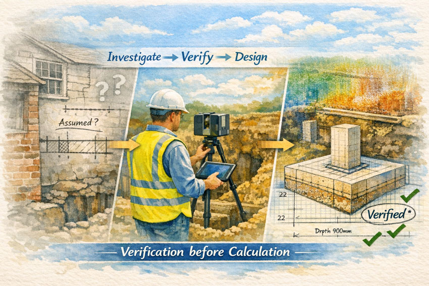
1. Investigation Is Part of Design
The media narrative highlights a simple truth: when we work with existing structures, the ground and foundations are not background details—they are primary design inputs.
Good practice means:
Treating site verification as a formal stage of the project
Making recommendations for geotechnical or structural checks early
Being clear about what is known and what is assumed
A design based only on drawings is never as reliable as one based on verified conditions.
2. Make Assumptions Visible
News coverage often shows that problems grow in the grey space between architect, engineer, and builder.
Helpful habits include:
Keeping an assumptions register shared by the whole team
Noting on drawings what has been confirmed on site
Setting clear triggers for further investigation
When assumptions have owners, risks have boundaries.
3. Communication Is a Structural Element
Many reported disputes stem less from technical ability and more from gaps in communication.
Engineers can lead by:
Discussing uncertainties openly at the start
Confirming decisions in writing after meetings
Encouraging contractors to report unexpected conditions
Good communication is often cheaper than remediation.
4. Scope Changes = Risk Changes
Renovations rarely stay the same as the first sketch. Media accounts of failures frequently involve projects that grew beyond the original intent.
Better process includes:
Re-checking engineering scope whenever the design evolves
Linking approvals to stages of investigation
Pricing verification as a real deliverable, not an afterthought
Clarity of scope is a form of structural strength.
5. Document the Story of the Project
Journalists and lawyers both rely on records to understand what happened.
For engineers, simple steps make a big difference:
Photos tied to inspection notes
Short design basis statements
Emails confirming client instructions
Sketches of as-found conditions
Documentation is not defensive—it is professional memory.
6. Respect the Interface Between Old and New
The media coverage repeatedly points to the moment where new work met an older structure. That interface is where uncertainty lives.
Practical responses:
Specific checks on existing footings before adding load
Independent review for heritage or unknown construction
Monitoring after completion to confirm behaviour
The junction between old and new deserves the most attention.
7. The Courage to Pause
Perhaps the most human lesson from the reports is that engineers sometimes need to slow a project down.
Saying:
“We need more information before proceeding”
is not obstruction—it is professionalism.
Organisations that support this courage protect clients and engineers alike.
Turning Headlines into Better Practice
The story covered by The Mercury and the subsequent industry commentary do not need to be read as cautionary tales. They can be read as learning opportunities:
Investigate before you calculate
Make assumptions visible
Communicate uncertainty early
Document decisions clearly
Treat existing conditions with respect
These are the foundations of good engineering, long before concrete is poured.
Final Thought
Risk will always exist in renovation and brownfield work. What we control is the process we wrap around that risk.
When engineers focus on verification, transparency, and collaboration, projects become safer, clients are better served, and the profession grows stronger.
Good engineering is not only about correct numbers— it is about asking the right questions at the right time.
References
“Woodbridge homeowner wins huge payout after home cracked following two-storey extension” — The Mercury (Tasmania) 🔗 https://www.themercury.com.au/truecrimeaustralia/police-courts-tasmania/woodbridge-homeowner-wins-huge-payout-after-home-cracked-following-twostorey-extension/news-story/32fe411a57c2471be44962cba86100bd
Mobile 3D LiDAR Scanning Services Melbourne | Engineering-Grade Capture
Melbourne’s industrial landscape is built on decades of growth—factories expanded in stages, plant modified during shutdowns, and buildings adapted to new processes. The challenge today is that many of these facilities no longer match their original drawings.
Mobile 3D LiDAR scanning services solve that problem by capturing the site exactly as it exists, providing engineers, designers, and fabricators with reliable data to work from—without guesswork.
At Hamilton By Design we bring engineering-grade reality capture directly to your Melbourne site. Our mobile LiDAR workflows are designed to support real projects: shutdown upgrades, conveyor installations, brownfield modifications, and compliance documentation.
Capture the Real Site – Not an Assumption
Traditional measuring methods struggle in complex industrial environments. Pipe bridges, mezzanines, mixed generations of equipment, and tight access areas make manual measurement risky and inaccurate.
Mobile LiDAR scanning delivers:
Millimetre-level point clouds of structures and equipment
Accurate tie-in points for new installations
Clearance checks for conveyors, elevators, and pipework
As-built records for compliance and asset management
Digital twins ready for design and clash detection
One site visit can capture more information than weeks of manual survey.
A Service Built for Melbourne Industry
From the inner west manufacturing belt to the northern logistics hubs and south-east processing plants, Melbourne projects share common pressures:
Short shutdown windows
Ageing plant with incomplete drawings
Multiple contractors working in the same space
Increasing safety and compliance requirements
Our mobile 3D LiDAR scanning services are structured to fit these realities. Most sites can be captured in a single day with minimal disruption to operations. Extra detail is focused around critical interfaces so new equipment fits first time.
Engineering First – Scanning With Purpose
We are not just data collectors. Hamilton By Design is an engineering business that uses scanning as the foundation for practical outcomes.
From a Melbourne scan we can deliver:
Registered point clouds in industry formats
AutoCAD & SOLIDWORKS models
General arrangement drawings
Fabrication-ready models
Clash and tolerance reports
Documentation for Safe Design reviews
Because the team understands fabrication and installation, the data is captured with the end goal in mind—equipment that bolts in without rework.
Applications Across Melbourne
Mobile LiDAR scanning supports a wide range of sectors:
Food & beverage processing
Recycling and resource recovery
Warehousing and logistics
Water & wastewater facilities
Manufacturing upgrades
Conveyor and bulk handling
Heritage building retrofits
Vehicle and specialised fit-outs
Whether it’s a small workshop in Dandenong or a complex plant in the western suburbs, the approach is the same: capture once, design with confidence.
Reduce Risk Before You Build
The cost of getting measurements wrong is far higher than the cost of a scan:
Delayed shutdowns
Steel that doesn’t fit
Emergency redesigns
Additional crane and labour hire
Compromised safety outcomes
Mobile 3D LiDAR scanning removes those uncertainties at the start of the project, giving Melbourne businesses control over time, budget, and risk.
Booking & Delivery
One day onsite is typically sufficient for most facilities
Registered point cloud delivered promptly
CAD outputs tailored to your design platform
50% deposit with purchase order, balance on delivery
Our calendar fills quickly around Melbourne shutdown periods—early booking ensures your project stays on track.
Talk to an Engineering-Led Scanning Team
If you’re planning an upgrade or need accurate as-builts in Melbourne, let’s capture the site properly before design begins.
Hamilton By Design – Mobile 3D LiDAR Scanning Services Engineering-grade capture for real industrial projects.
Fabrication Integrated Modelling (FIM): Why It’s the Future for Local Fabricators
Why It Is the Future for Local Fabricators
The fabrication industry is undergoing a fundamental transformation. Increasing project complexity, tighter tolerances, compressed schedules, labour shortages, and rising material costs are placing unprecedented pressure on fabricators — particularly local workshops operating in competitive markets. At the same time, clients are demanding greater certainty: certainty of fit, certainty of schedule, and certainty of cost.
Traditional fabrication workflows, built around 2D drawings and manual interpretation, are no longer sufficient to meet these expectations. They rely heavily on experience, assumptions, and rework — all of which introduce risk. In this environment, Fabrication Integrated Modelling (FIM) is emerging not as a luxury, but as a necessity.
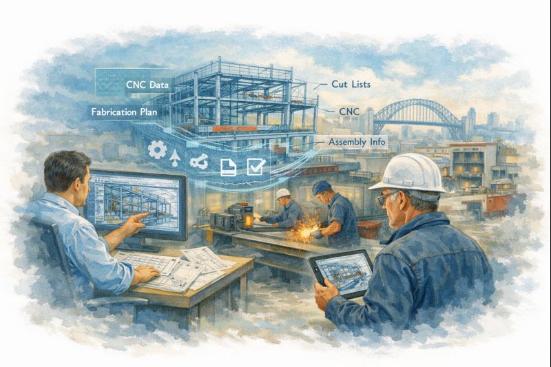
FIM represents a shift from drawing-based fabrication to model-driven fabrication, where a single, coordinated digital model governs design intent, fabrication detailing, procurement, machining, assembly, and installation. For local fabricators, this shift offers a path to higher productivity, improved margins, and long-term relevance in an evolving industry.
What Is Fabrication Integrated Modelling (FIM)?
Fabrication Integrated Modelling is a methodology where the fabrication model becomes the primary source of truth across the entire project lifecycle. Instead of treating design, drafting, fabrication, and installation as disconnected stages, FIM integrates them into a continuous digital workflow.
In an FIM environment:
Engineering intent is embedded directly into the model
Fabrication constraints are considered from the outset
Quantities, tolerances, and interfaces are defined digitally
Fabrication data flows directly to machines and shop documentation
Installation sequencing is validated before material is cut
The model is not merely a visual aid — it is a fully informed digital prototype of the fabricated asset.
From Drawings to Data: A Fundamental Shift
Historically, fabrication has relied on 2D drawings as the primary communication tool. These drawings require interpretation by drafters, trades, and supervisors, each introducing assumptions based on experience and context. While this approach has worked for decades, it becomes increasingly fragile as projects grow more complex.
Fabrication Integrated Modelling replaces interpretation with explicit data. Hole locations, weld preparations, connection details, clearances, and tolerances are all defined within the model. This reduces ambiguity and ensures that everyone — from estimator to machine operator — is working from the same information.
The result is a dramatic reduction in errors, clarifications, and rework.
Why FIM Is Gaining Momentum Now
Several industry pressures are accelerating the adoption of FIM:
Increasing complexity of industrial and infrastructure projects
Reduced tolerance for errors during shutdowns and brownfield upgrades
Labour shortages and loss of experienced trades
Higher expectations for schedule and cost certainty
Growing integration of CNC and automated fabrication equipment
FIM addresses these challenges by improving coordination, predictability, and efficiency at the source — before fabrication begins.
Key Benefits of Fabrication Integrated Modelling
Reduced Errors and Rework
Rework is one of the most significant drains on fabrication profitability. Errors discovered on the workshop floor or during installation often result in cascading impacts: delays, additional labour, material waste, and strained relationships with clients.
By resolving interfaces, clashes, and tolerances digitally, FIM enables fabricators to identify and eliminate issues before steel is cut. Assemblies are tested virtually, connections are validated, and fit-up risks are significantly reduced.
This proactive approach shifts problem-solving upstream, where changes are faster, cheaper, and less disruptive.
Improved Fabrication Efficiency and Throughput
Fabrication speed is not achieved by rushing work — it is achieved by removing uncertainty. FIM provides clarity on what needs to be fabricated, in what order, and to what tolerance.
Benefits include:
Clear fabrication sequencing
Reduced downtime waiting for clarifications
Better planning of labour and machine utilisation
More predictable workshop flow
Local fabricators using FIM often report smoother operations, fewer interruptions, and a higher percentage of “right-first-time” components.
Better Use of Skilled Labour
Skilled trades are becoming harder to find and retain. Fabrication Integrated Modelling helps maximise the value of skilled workers by giving them better information, not more guesswork.
Fitters receive assemblies that align as expected. Welders focus on quality rather than correcting geometry. Supervisors make decisions based on accurate model data rather than assumptions. Apprentices gain clarity and confidence by working from model-based instructions.
Rather than replacing experience, FIM captures and amplifies it.
Seamless Integration with CNC and Fabrication Equipment
One of the strongest advantages of FIM is its ability to connect directly with modern fabrication equipment. The same model used for coordination and verification can generate machine-ready data, including:
NC files for beam lines and plate processors
Cut lists and nesting data
Part numbers and assembly marks
Machining references
This eliminates duplication of effort and reduces the risk of transcription errors. It also shortens the time between design approval and fabrication start, improving responsiveness to project changes.
Competitive Advantage for Local Fabricators
Local fabricators often compete with offshore suppliers on price alone — a contest that is difficult to win. FIM allows local workshops to compete on value rather than cost.
Key differentiators enabled by FIM include:
Faster response to changes
Higher confidence in fit-up for complex or brownfield sites
Reduced installation risk
Stronger collaboration with engineers and constructors
When site conditions change — as they inevitably do — local fabricators using FIM can adapt quickly, update models, and deliver revised components without significant disruption. This agility is a powerful advantage over remote fabrication alternatives.
FIM in Brownfield and Upgrade Projects
Brownfield projects present some of the greatest challenges in fabrication. Existing assets rarely match legacy drawings, and tolerances are often tight. Discovering misalignment during installation can result in costly delays and extended shutdowns.
Fabrication Integrated Modelling, often combined with accurate site capture, allows fabricators to design and fabricate components that align with actual site conditions rather than assumptions.
This approach reduces:
On-site modifications
Temporary works
Installation delays
Safety risks associated with forced fit-ups
For local fabricators servicing industrial plants and operational facilities, FIM is rapidly becoming an expected capability.
Financial Benefits: Protecting Margins, Not Just Schedules
While FIM is often associated with speed and accuracy, its most important benefit may be margin protection.
Model-based workflows enable:
More accurate pricing through reliable quantities
Reduced contingency allowances
Predictable labour and machine hours
Lower material waste
Fewer disputes and variations
By increasing certainty, FIM allows fabricators to price work confidently rather than defensively. Over time, this leads to healthier margins and more sustainable operations.
Earlier Engagement and Better Project Outcomes
Fabricators who adopt FIM often find themselves involved earlier in projects. Engineers and asset owners increasingly recognise the value of fabrication input during design development.
Early collaboration enables:
Design for manufacture and assembly
Smarter connection strategies
Reduced installation complexity
Improved safety outcomes
This shifts the fabricator’s role from reactive supplier to active project partner, strengthening relationships and improving project outcomes for all parties.
Overcoming Barriers to Adoption
Adopting Fabrication Integrated Modelling requires investment — not only in software and systems, but in people and processes. Common challenges include:
Training requirements
Changes to established workflows
Initial productivity adjustments
Cultural resistance to new methods
Successful fabricators address these challenges incrementally. They start with pilot projects, focus on repeatable wins, and work closely with engineering and modelling partners to build capability over time.
The risk of maintaining outdated workflows is increasingly greater than the risk of change.
The Future of Fabrication: Integrated Digital Ecosystems
FIM is not the final destination — it is the foundation for a more connected fabrication industry. As digital maturity increases, fabrication models will increasingly link to:
Digital twins
Quality assurance records
Traceability and compliance systems
Asset management platforms
Automated inspection and verification
In this future, the fabrication model becomes a long-term asset, supporting not only construction but operation and maintenance.
Why Fabrication Integrated Modelling Is the Future for Local Fabricators
Local fabrication is not disappearing — it is evolving. Workshops that continue to rely solely on 2D drawings and manual processes will face increasing pressure from cost, risk, and competition. Those that embrace Fabrication Integrated Modelling will position themselves for long-term success.
By adopting FIM, local fabricators can:
Deliver higher quality with greater confidence
Reduce rework and wasted effort
Protect margins in competitive markets
Strengthen relationships with engineers and clients
Build resilient, future-ready businesses
Fabrication Integrated Modelling is not about replacing trades or experience. It is about supporting them with better information, clearer intent, and integrated workflows.
For local fabricators willing to invest in capability and collaboration, FIM is not just the future — it is the pathway to remaining relevant, competitive, and profitable in an increasingly digital industry.
To provide the best experiences, we use technologies like cookies to store and/or access device information. Consenting to these technologies will allow us to process data such as browsing behaviour or unique IDs on this site. Not consenting or withdrawing consent, may adversely affect certain features and functions.
Functional
Always active
The technical storage or access is strictly necessary for the legitimate purpose of enabling the use of a specific service explicitly requested by the subscriber or user, or for the sole purpose of carrying out the transmission of a communication over an electronic communications network.
Preferences
The technical storage or access is necessary for the legitimate purpose of storing preferences that are not requested by the subscriber or user.
Statistics
The technical storage or access that is used exclusively for statistical purposes.The technical storage or access that is used exclusively for anonymous statistical purposes. Without a subpoena, voluntary compliance on the part of your Internet Service Provider, or additional records from a third party, information stored or retrieved for this purpose alone cannot usually be used to identify you.
Marketing
The technical storage or access is required to create user profiles to send advertising, or to track the user on a website or across several websites for similar marketing purposes.