Rockhampton a Unique Environment for Engineering

Why Rockhampton Is a Unique Environment for Engineering & Digital Technology

Rockhampton stands out for several reasons that directly influence how engineering and design work is executed in the region.

1. A City at the Centre of Agriculture, Mining and Defence

Few regional cities in Australia support as many sectors simultaneously:

  • cattle production & feedlots
  • abattoirs and food-processing plants
  • mining workflow (Bowen Basin)
  • fabrication and workshop environments
  • major road & rail logistics
  • defence operations at Shoalwater Bay

This diversity creates an environment where brownfield projects, plant upgrades and operational changes are constant โ€” and where accurate digital engineering is invaluable.

2. A Heritage-Rich Built Environment

Rockhamptonโ€™s colonial architecture and historic precincts add engineering complexity, especially for:

  • renovation and extension planning
  • capturing building geometry
  • ensuring compliance during upgrades
  • modelling concealed or irregular structures

Accurate scanning and modelling reduce the risks associated with modifying older buildings.

3. A Rapidly Growing Industrial Corridor

With expansions across Gracemere, Parkhurst and the Port Alma supply chain, Rockhampton is strengthening its role as a:

  • fabrication hub
  • transport distribution centre
  • industrial service precinct

Digital engineering ensures these facilities deliver maximum efficiency with minimal downtime.
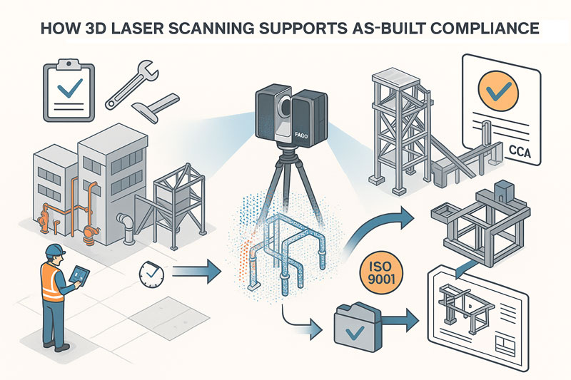

3D LiDAR Laser Scanning: Rockhamptonโ€™s Path to More Accurate, Data-Driven Projects

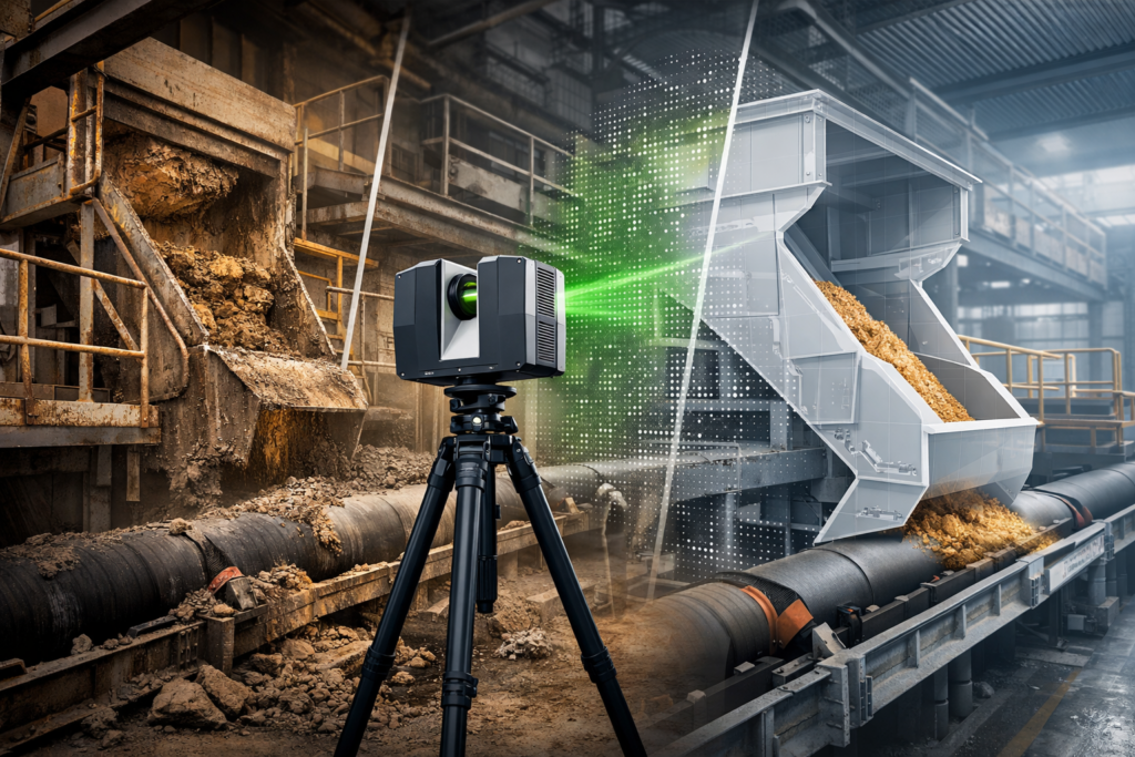
One of the biggest challenges in Central Queensland is managing complexity in brownfield industrial environments: tight tie-in points, undocumented modifications, legacy equipment, unknown clearances and misaligned plant sections.

This is exactly where 3D LiDAR scanning becomes a game-changing tool.

Hamilton By Design uses engineering-grade scanning to produce:

  • complete as-built environments
  • millimetre-accurate spatial data
  • structural geometry and deflection insights
  • clash detection for new installations
  • alignment checks for equipment
  • precise digital documentation for tendering and fabrication

Learn more about our scanning process here:
3D Laser Scanning โ€“ https://www.hamiltonbydesign.com.au/home/3d-lidar-scanning-digital-quality-assurance/3d-laser-scanning/

For Rockhampton industries, the value is immediate:

  • reduced rework and fewer shutdown overruns
  • accurate fit-up when fabricators install new components
  • better engineering decisions based on real data
  • faster turnaround for designs and feasibility planning

From abattoirs to feed mills, mining workshops to energy infrastructure, LiDAR scanning ensures every project begins with precise, reliable site information.


3D Modelling & Drafting: Turning Reality Into Intelligent Engineering Models

Once the point cloud is captured, Hamilton By Design transforms the data into:

  • SolidWorks parts and assemblies
  • mechanical models for plant upgrades
  • fabrication-ready drawings (GA, detail, isometric & BOMs)
  • structural models for platforms, supports, conveyors and frames
  • mechanical layout concepts and optimisation studies

For Rockhampton businesses, this is particularly valuable because:

  • fabrication teams rely on correct geometry
  • shutdown windows are small
  • misaligned or undocumented equipment is common
  • design changes often must occur quickly

With 3D modelling, plant owners, contractors and fabricators can visualise the project before steel is cut โ€” dramatically improving accuracy and reducing cost.


Mechanical Engineering for Rockhamptonโ€™s Industrial & Agricultural Sectors

Rockhamptonโ€™s diverse economy means the region is constantly upgrading:

  • processing plants
  • abattoirs
  • feed mills
  • grain-handling systems
  • water-treatment infrastructure
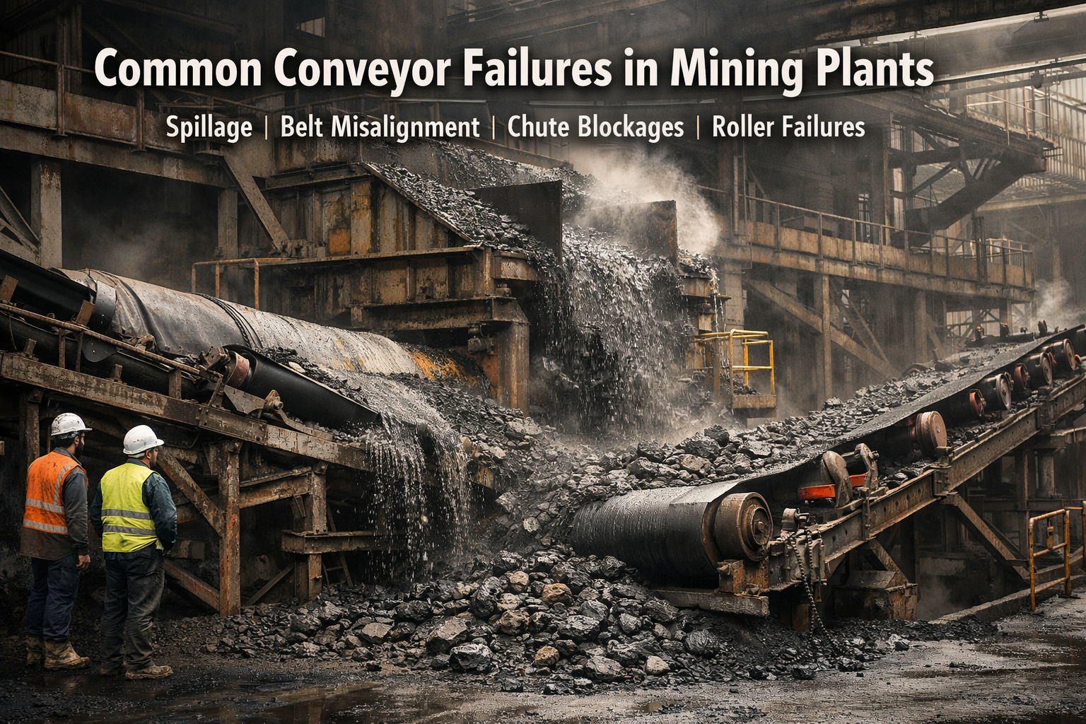
  • conveyor systems
  • workshops and industrial machinery

Hamilton By Design provides engineering support such as:

  • mechanical design for new or upgraded equipment
  • structural assessments on frames, platforms, chutes and conveyors
  • vibration, deflection and alignment analysis
  • flow optimisation for materials-handling systems
  • FEA (Finite Element Analysis) for components and assemblies
  • lifting, access and maintenance design

Our engineer-led workflow ensures that every design is based on reality โ€” captured by LiDAR and validated through modelling and analysis.


How Digital Engineering Helps Rockhamptonโ€™s Key Industries

1. Beef Processing & Agri-Food Operations

Rockhamptonโ€™s processing facilities are often complex, space-constrained and continuously operating.

Scanning assists with:

  • plant upgrades
  • layout efficiency studies
  • tie-in accuracy for new conveyors or equipment
  • compliance documentation

2. Bowen Basin Mining Support

Rockhampton is a major hub for:

  • mining contractors
  • fabrication workshops
  • equipment repair
  • maintenance logistics

LiDAR scanning and engineering reduce rework in fabricated components destined for:

  • Moranbah
  • Blackwater
  • Middlemount
  • Dysart and surrounding mines

3. Industrial Precincts & Port Supply Chains

Industrial estates across Parkhurst and Gracemere benefit from:

  • warehouse fit-outs
  • crane runway checks
  • processing-line layout design
  • mechanical and structural upgrades

4. Heritage & Architectural Redevelopment

Scanning enables:

  • accurate modelling of old buildings
  • conflict detection for new internal services
  • faรงade preservation planning

No risk of relying on inaccurate tape-measure surveys.


A Fully Integrated Workflow: Scan โ†’ Model โ†’ Engineer โ†’ Deliver

One of the biggest advantages Hamilton By Design provides to Rockhampton businesses is single-source accountability.

Our streamlined process includes:

  1. 3D LiDAR scanning of the site
  2. Processing & registering point-cloud data
  3. SolidWorks modelling of the environment
  4. Engineering assessments & calculations
  5. Fabrication-ready drawings
  6. Digital QA for installation

Thereโ€™s no handover between scanning companies, designers and engineers โ€” everything is delivered by one team, reducing miscommunication and improving project outcomes.


Rockhamptonโ€™s Future Is Digital โ€” And Weโ€™re Ready to Support It

Rockhampton is experiencing a period of sustained growth driven by agriculture, mining, defence and industrial expansion. As facilities upgrade and capacity increases, accurate engineering data, digital design tools and advanced scanning technology will be central to delivering smarter, safer and more efficient projects.

Hamilton By Design logo displayed on a blue tilted rectangle with a grey gradient background
3D LiDAR scanning and 3D modelling service button โ€” laser scanner capturing a point cloud for engineering and CAD modelling
Mechanical engineering services

Hamilton By Design is proud to support Central Queensland with:

  • 3D LiDAR laser scanning
  • Mechanical engineering consulting
  • 3D modelling and drafting
  • Digital documentation and quality assurance

Whether youโ€™re planning an upgrade to a processing plant, modernising a workshop, designing a conveyor system or documenting an entire facility, our engineering-led team provides the precision and reliability your project needs.

Our Clients

Name
Would you like us to arrange a phone consultation for you?
Address
Finite Element Analysis (FEA) engineering simulation button
Mechanical engineering services

How 3D Laser Scanning Supports As-Built Documentation Under Australian Building Codes & Legal Requirements

illustration of 3d scanning and building code of australia

1. What the Building Code of Australia (BCA) and Australian Standards Require

While the BCA (part of the National Construction Code โ€“ NCC) does not mandate 3D laser scanning, it does mandate that:

You must provide accurate, verifiable as-built documentation, including:

  • As-built drawings reflecting what was actually constructed
  • Evidence that construction aligns with design intent and approvals
  • Documentation for certification, compliance, commissioning and future maintenance

These requirements flow through:

  • NCC Volume 1 โ€“ Construction documentation, fire systems, mechanical services
  • AS 1100 โ€“ Technical drawing standards
  • AS 5488 โ€“ Subsurface utility information
  • AS 9001/ISO 9001 โ€“ Quality management documentation
  • State-based WHS / Plant Safety legislation
  • Engineering registration Acts (NSW, QLD, VIC)
  • Client-specific QA frameworks (e.g., TfNSW Digital Engineering, mining compliance standards, government project handover requirements)

These frameworks all emphasise accuracy, traceability, verification and record-keeping.


2. Common Problems with Traditional As-Built Documentation

Most non-compliance issues in handover packages arise because traditional methods rely on:

  • Manual tape measurements
  • Incomplete mark-ups on outdated drawings
  • Limited site access
  • Errors stacking up across multiple trades
  • No accurate record of clashes and deviations
  • No evidence trail for certifiers

This often results in:

  • Disputes between builders, certifiers and subcontractors
  • Rework costs during commissioning
  • Safety risks due to undocumented services or variations
  • Delays in obtaining Occupation Certificates (OC)

3. How 3D Laser Scanning Directly Supports Legal & BCA/NCC Compliance

โœ” 3D Scanning Provides โ€œVerified As-Constructed Evidenceโ€

Point clouds record geometry with millimetreโ€“level accuracy, giving:

  • Audit-proof evidence of what exists
  • Time-stamped scanning sessions
  • A defensible digital record for certifiers, engineers and auditors

This is extremely helpful for:

  • Compliance sign-off
  • Dispute resolution
  • Safety compliance
  • Future upgrades or modifications

โœ” Produces Accurate As-Built Drawings That Meet AS 1100 Requirements

Laser scanning allows you to generate:

  • Certified 2D as-built drawings
  • 3D models
  • Fabrication-ready details
  • Clash-free spatial coordination drawings

This ensures:

  • Dimensions are correct
  • Penetrations, fall directions, service locations and structural offsets are true to field conditions
  • All documentation aligns with NCC-required accuracy

โœ” Eliminates Measurement Errors That Could Breach Compliance

Regulators and certifiers need as-built documents to match constructed work.

Laser scanning:

  • Removes subjective tape measurements
  • Captures difficult/unsafe areas safely
  • Ensures penetrations, ductwork, pipe routes and tolerances match required clearances
  • Supports inspections under NCC (fire, structural, mechanical, accessibility, plant rooms, etc.)

โœ” Simplifies BCA Documentation for Fire, Mechanical & Structural Systems

Scanning assists with validating:

Fire Safety Systems

  • Hydrants, hose reels, fire pump rooms
  • Fire damper locations
  • Egress paths and spatial compliance
  • Service penetrations

Mechanical Systems

  • Duct routes
  • Plant room layouts
  • Fan coil units / AHU placement
  • Shaft centre-lines
  • Compliant access paths

Structural Elements

  • Columns
  • Beams
  • Brackets
  • Plant mounts
  • Retrofitted steelwork
  • Tolerance checks

The point cloud provides certifiers with confidence that what was installed does not deviate from approved plans beyond allowable tolerances.


โœ” Strengthens ISO 9001 & Government QA Requirements

Most government tenders (TfNSW, Defence, Health Infrastructure, QBuild, etc.) require:

  • Traceable QA
  • As-constructed verification
  • Digital documentation

A 3D scan becomes proof of measurement, improving your QA process by providing:

  • Verifiable dimensional control
  • Pre-fabrication QA
  • Handover packages that exceed minimum compliance

4. How Hamilton By Design Can Position This Service

3D Laser Scanning Enables:

  • NCC-compliant as-built documentation
  • Faster certifier approval
  • Fewer construction disputes
  • Reduced rework during commissioning
  • Better safety compliance
  • Accurate digital twins for maintenance and lifecycle management

You can state (truthfully):

โ€œOur 3D scans provide defensible, audit-ready as-built records that satisfy NCC, engineering, and certification requirements. Certifiers appreciate the precision because it removes ambiguity and reduces approval delays.โ€


Hamilton By Design logo displayed on a blue tilted rectangle with a grey gradient background

Why Shutdown Parts Donโ€™t Fit

Finite Element Analysis (FEA) engineering simulation button
Mechanical engineering services

Accuracy of 3D LiDAR Scanning With FARO

Mechanical Engineering | Structural Engineering

Mechanical Drafting | Structural Drafting

3D CAD Modelling | 3D Scanning

Chute Design

Bridging Reality and Design: How 3D Scanning + 3D Modelling Supercharge Mining Process Plants

In mining and mineral processing environments, small mis-fits, outdated drawings, or inaccurate assumptions can translate into shutdowns, costly rework, or worse, safety incidents. For PMs, superintendents, engineering managers and plants operating under heavy uptime and safety constraints, combining 3D scanning and 3D modelling isnโ€™t just โ€œnice to haveโ€ โ€” itโ€™s becoming essential. At Hamilton By Design, weโ€™ve leveraged this combination to deliver greater predictability, lower cost, and improved safety across multiple projects.


What are 3D Scanning and 3D Modelling?

  • 3D Scanning (via LiDAR, laser, terrestrial/mobile scanners): captures the existing geometry of structures, equipment, piping, chutes, supports, tanks, etc., as a dense point cloud. Creates a digital โ€œreality captureโ€ of the plant in its current (often messy) state.
  • 3D Modelling: turning that data (point clouds, mesh) into clean, usable engineering-geometry โ€” CAD models, as-built / retrofit layouts, clash-detection, wear mapping, digital twins, etc.

The power comes when you integrate the two โ€” when the reality captured in scan form feeds directly into your modelling/design workflows rather than being a separate survey activity thatโ€™s then โ€œinterpretedโ€ or โ€œassumed.โ€


Why Combine Scanning + Modelling? Key Benefits

Here are the main advantages you get when you deploy both in an integrated workflow:

BenefitWhat it Means for PMs / Engineering / Plant OpsExamples / Impacts
Accuracy & Reality VerificationVerify whatโ€™s actually in the plant vs what drawings say. Identify deformations, misalignments, wear, obstructions, or changes that werenโ€™t captured in paper drawings.Mill liner wear profiles; chute/hopper buildup; misaligned conveyors or supports discovered post-scan.
Reduced Risk, Safer AccessScanning can be done with limited or no shutdown, and from safer vantage points. Less need for personnel to enter hazardous or confined spaces.Scanning inside crushers, under conveyors, or at height without scaffolding.
Time & Cost SavingsFaster surveying; fewer repeat field trips; less rework; fewer surprises during shutdowns or retrofit work.Scan once, model many; clashes found in model instead of in the field; pre-fabrication of replacement parts.
Better Shutdown / Retrofit PlanningUse accurate as-built models so new equipment fits, interferences are caught, installation time is optimized.New pipelines routed without conflict; steelwork/supports prefabricated; shutdown windows shortened.
Maintenance & Asset Lifecycle ManagementScan history becomes a baseline for monitoring wear or deformation. Enables predictive maintenance rather than reactive.Comparing scans over time to track wear; scheduling relining of chutes; monitoring structural integrity.
Improved Decision Making & VisualisationEngineers, superintendents, planners can visualise the plant as it is โ€” space constraints, access routes, clearances โ€” before making decisions.Clash-detection between new and existing frames; planning maintenance access; safety audits.
Digital Twin / Integration for Future-Ready PlantOnce you have accurate geometric models you can integrate with IoT, process data, simulation tools, condition monitoring etc.Digital twins that simulate flow, energy use, wear; using scan data to feed CFD or FEA; feeding into operational dashboards.

Challenges & How to Overcome Them

Of course, there are pitfalls. Ensuring scanning + modelling delivers value requires attention to:

  • Planning the scanning campaign (scan positions, control points, resolution) to avoid shadow zones or missing data.
  • Choosing hardware and equipment that can operate under plant conditions (dust, vibration, temperature, restricted access).
  • Processing & registration of point clouds, managing the large data sets, and ensuring clean, usable models.
  • Ensuring modelling workflow aligns with engineering design tools (CAD systems, formats, tolerances) so that the scan data is usable without excessive cleanup.
  • Maintaining the model: when plant layouts or equipment change, keeping the scan or model up to date so your decisions are based on recent reality.

At Hamilton By Design we emphasise these aspects; our scan-to-CAD workflows are built to align with plant engineering needs, and we help clients plan and manage the full lifecycle.


Real World Applications in Mining & Process Plants

Hereโ€™s how combined scanning + modelling is applied (and what you might look for in your own facility):

  • Wear & Relining: scanning mill, crusher liners, chutes or hoppers to model wear profiles; predict failures; design replacement parts that fit exactly.
  • Retrofits & Expansions: mapping existing steel, pipe racks, conveyors, etc., creating accurate โ€œas builtโ€ model, checking for clashes, optimizing layouts, prefabricating supports.
  • Stockpile / Volumetric Monitoring: using scans or LiDAR to measure stockpile volumes for planning and reporting; integrating with models to monitor material movement and flow.
  • Safety & Clearance Checking: verifying that walkways, egress paths, platforms have maintained their clearances; assess structural changes; check for deformation or damage.
  • Shutdown Planning: using accurate 3D models to plan the scope, access, scaffold/frame erection, pipe removal etc., so shutdown time is minimised.

Why Choose Hamilton By Design

To get full value from the scan + model combination, you need more than just โ€œweโ€™ll scan itโ€ or โ€œweโ€™ll make a modelโ€ โ€” you need a partner who understands both the field realities and the engineering rigour. Here’s where Hamilton By Design excels:

  • Strong engineering experience in mining & processing plant settings, so we know what level of detail, what tolerances, and what access constraints matter.
  • Proven tools & workflows: from LiDAR / laser scanner work that captures site conditions even under harsh conditions, to solid CAD modelling/reporting that aligns with your fabrication/installation requirements.
  • Scan-to-CAD workflows: not just raw point clouds, but models that feed directly into design, maintenance, procurement and operations.
  • Focus on accuracy, safety, and reduced downtime: ensuring that field work, design, installation etc., are as efficient and risk-averse as possible.
  • Use of modern digital techniques (digital twins, clash detection etc.) so that data isnโ€™t just stored, but actively used to drive improvements.

Practical Steps to Get Started / Best Practice Tips

If youโ€™re managing a plant or engineering project, here are some steps to adopt scanning + modelling optimally:

  1. Define Clear Objectives: What do you want from this scan + model? Wear profiles, retrofit, layout changes, safety audit etc.
  2. Survey Planning: Decide scan positions, control points, resolution (density) based on the objectives and site constraints. Consider access, safety, shutdown windows.
  3. Use Appropriate Hardware: Choose scanners suited to environment (dust, heat), also ensure regulatory and IP protection etc.
  4. Data Processing & Modelling Tools: Have the capacity/software to register, clean, mesh or extract CAD geometry.
  5. Integrate into Existing Engineering Processes: Ensure the outputs are compatible with your CAD standards, procurement, installation etc.
  6. Iterate & Maintain: Frequent scans over time to track changes; update models when plant changes; feed maintenance, design and operations with new data.

Conclusion

In mining process plants, time, safety, and certainty matter. By combining 3D scanning with sound 3D modelling you donโ€™t just get a snapshot of your plant โ€” you gain a powerful toolset to reduce downtime, avoid rework, improve safety, and enhance decision-making.

If youโ€™re responsible for uptime, capital works, maintenance or process improvements, this integration can reshape how you plan, maintain, and operate. At Hamilton By Design, weโ€™re helping clients in Australia harness this power โ€” turning reality into design confidence, and giving stakeholders peace of mind that the layout, equipment, and safety are aligned not to yesterdayโ€™s drawings but to todayโ€™s reality.

Name
Would you like us to arrange a phone consultation for you?
Address
3D LiDAR scanning and 3D modelling service button โ€” laser scanner capturing a point cloud for engineering and CAD modelling
Mechanical engineering services
Finite Element Analysis (FEA) engineering simulation button
Mechanical engineering services

Engineering Integrity, Failure Evolution, and Energy Transition: A Mechanical Engineerโ€™s Perspective on Australiaโ€™s Ageing Coal Fleet

This paper examines the mechanical degradation, failure mechanisms, and system-level reliability implications of Australiaโ€™s ageing coal-fired power generation assets, focusing on Callide Power Station (Queensland) and Yallourn Power Station (Victoria). Both stations have experienced significant mechanical failures in the past five years, exposing vulnerabilities in maintenance, asset management, and risk governance under conditions of declining reinvestment.
From a mechanical engineering standpoint, these failures illustrate the predictable end-of-life behaviour of large rotating and pressure-bound systems when maintenance expenditure, material renewal, and operational monitoring decline. The paper argues that sustained industrial reliabilityโ€”and thus national energy and employment securityโ€”requires engineering-informed policy that balances decarbonisation with technical integrity management.


Coal-fired power stations are among the most complex mechanical systems ever built in Australia. They integrate high-temperature, high-pressure thermodynamic processes with massive rotating equipment, lubrication systems, and precision alignment tolerances.

From a mechanical engineerโ€™s perspective, their reliability depends on three interlinked pillars:

  1. Structural and material integrity,
  2. Lubrication and vibration control, and
  3. Predictive maintenance and monitoring.

However, as the nation accelerates toward renewable transition targets, investment in these legacy systems has declined. Mechanical failures at Callide and Yallourn are therefore not random accidents but the mechanical manifestation of economic and policy choices.

This analysis seeks to understand those failures in engineering terms, predict future risks, and outline how a re-commitment to industrial infrastructure and jobs requires a concurrent commitment to mechanical reliability.


Technical Overview of Recent Failures

Callide Power Station

Callideโ€™s units span several generations of design and material technology. The C4 explosion (2021) was catastrophic: the failure originated within the turbine hall, leading to structural collapse and large-scale ejection of debris.
Subsequent analysis by CS Energy and external investigators identified battery charger replacement errors, inadequate isolation protocols, and loss of process safety discipline as initiators.

From an engineering integrity perspective, the incident represents a compound failure:

  • Mechanical systems operated under degraded conditions;
  • Electrical and process-control systems failed to detect early anomalies;
  • Organisational maintenance controls were insufficient to interrupt escalation.

Later failures โ€” including the C3 boiler pressure event (2025) and cooling tower collapse (2022) โ€” further confirm that structural materials, corrosion protection, and load-carrying assemblies had entered the fatigueโ€“creep interaction phase of their service life.

Yallourn Power Station

At Yallourn, the August 2025 low-pressure turbine dislodgement occurred after decades of vibration monitoring alarms and bearing wear signals. Earlier (2024) shutdowns for โ€œhigh vibration alarmsโ€ indicated growing rotor dynamic instability.
When the Unit 2 turbine dislodged, the damage pattern suggested bearing wear, misalignment, or bolt relaxation leading to component displacement.

In mechanical engineering terms, this is a classic late-life failure sequence:

  1. Fatigue crack initiation in critical load-carrying components (rotor or coupling bolts),
  2. Progressive loosening and unbalance,
  3. Dynamic amplification under operating RPM,
  4. Catastrophic structural displacement.

The turbineโ€™s dislodgement was therefore an expected end-of-life event, accelerated by reduced overhaul investment and ageing metallurgical properties.


Comparative Engineering Analysis

Engineering DimensionCallideYallournComparison / Insight
Failure TypeExplosion / Pressure Containment BreachTurbine Mechanical DislodgementCallide shows energy-release failure; Yallourn a structural integrity loss.
Root Mechanical CauseOverpressure / process safetyFatigue, unbalance, bearing or bolt failureBoth reflect cumulative degradation.
Indicative Material StateCreep-fatigued pressure shells; corroded supportsThermal-fatigued steel, worn journalsMetallurgical ageing dominates both.
Maintenance CultureProcess-safety erosionReactive, โ€œrun-to-retirementโ€Organisational degradation common factor.
System OutcomeExplosion and total destructionSevere mechanical damage, unit outageBoth reduce grid reliability and reveal systemic neglect.

These failures share a unifying pattern recognised in mechanical reliability theory:

Late-life degradation compounded by maintenance deferral and organisational fatigue produces cascading mechanical failure modes that were once preventable.


Predicting Future Failure Behaviour

Mechanical engineers use reliability-centred maintenance (RCM) models to quantify end-of-life risk.
For rotating equipment, mean time to failure (MTTF) typically decreases exponentially once fatigue propagation exceeds ~70 % of material endurance life.

Data from the National Electricity Market (NEM) indicates:

  • Forced outage frequency has doubled since 2012.
  • Vibration and lubrication alarms are rising in frequency.
  • Unit unavailability correlates strongly (Rยฒ > 0.8) with turbine age and last major overhaul date.

Projected forward, these indicators imply that without major overhauls or component replacements, most Australian coal units will face critical mechanical reliability decline by 2032โ€“2035.


Engineering Economics and Policy Interaction

From an engineering management perspective, the problem is not purely technical โ€” it is thermo-economic.

  • A major turbine retrofit (~A$25โ€“40 million per unit) is uneconomic for plants scheduled for closure in under a decade.
  • Operators thus defer maintenance, accepting rising mechanical risk.
  • The probability of catastrophic failure increases sharply as the cost of prevention declines below the cost of repair.

This is the engineering expression of policy-induced obsolescence: political commitments to retire coal reduce the incentive to sustain its mechanical integrity, even while industries still depend on its output.


Industrial Reliability and the Employment Interface

Reliable baseload power is the foundation for industrial continuity.
From the standpoint of a mechanical engineer, industrial productivity is a function of mechanical uptime: Productivity=f(Power Reliability,Maintenance Efficiency)\text{Productivity} = f(\text{Power Reliability}, \text{Maintenance Efficiency})Productivity=f(Power Reliability,Maintenance Efficiency)

When power generation becomes intermittentโ€”whether from renewable intermittency or coal unreliabilityโ€”industrial operations must compensate with redundancy, backup generation, or load-shedding. These add capital and operational costs that ultimately affect employment.

Regional Implications

  • Queensland retains a stronger firm power horizon (coal + gas + hydro until ~2035), giving industry more operational certainty.
  • Victoria, by contrast, will face a reliability inflection point after Yallourn (2028) and Loy Yang A (2035) closures.

Without firm generation or large-scale storage online, manufacturing regions risk power volatilityโ€”directly translating to production downtime and job insecurity.


Engineering the Transition: Commitment to Jobs and Infrastructure

From a mechanical engineering ethics and systems standpoint, a commitment to industry must be synonymous with a commitment to mechanical reliability.
That requires three converging actions:

Asset Integrity Management:
Continuous structural health monitoring, vibration analysis, and overhaul planning for remaining thermal units.
Even in decline, they must be safely and predictably retired.

Design and Commissioning of Replacement Systems:
Engineers must ensure that renewable generation, storage, and transmission assets meet equivalent reliability and maintainability standards.
This includes redundancy design, grid inertia replacement, and mechanical resilience of large rotating machinery (e.g., pumped hydro, turbines, bearings).

Workforce Transition as Engineering Continuity:
The skills used to maintain turbines, bearings, and boilers are transferable to wind, hydro, and hydrogen equipment.
Protecting those jobs preserves both mechanical capability and national energy security.


Engineering Conclusions

From a mechanical engineerโ€™s viewpoint, the failures at Callide and Yallourn are textbook case studies of end-of-life degradation under policy-driven neglect.
They illustrate that:

  1. Mechanical degradation is predictable โ€” vibration, lubrication, and thermal-stress indicators were present years before failure.
  2. Organisational and policy decisions override engineering recommendations โ€” maintenance deferral was economic, not technical.
  3. Systemic reliability cannot be sustained without mechanical investment โ€” whether in turbines, batteries, or hydro equipment, engineering integrity remains central.
  4. A national commitment to industry equals a commitment to engineering.

If Australia seeks to safeguard its industrial base and employment, it must invest not only in new energy technologies but in the mechanical soundness of the systems that bridge the transition.
Neglecting this will reproduce the same failure patternsโ€”just in new forms of infrastructure.


References (Indicative)

  • CS Energy (2024). Callide C4 Incident Investigation Summary.
  • WattClarity (2025). Analysis of Yallourn Unit 2 Trip and Frequency Response.
  • AEMO (2025). Generator Reliability Performance Report.
  • EnergyAustralia (2025). Yallourn Mechanical Maintenance Overview.
  • IEEFA (2025). Delaying Coal Power Exits: Engineering and Economic Implications.
  • ASME (2023). Guidelines on Turbine Rotor Life Assessment and Remaining Life Prediction.
3D LiDAR scanning and 3D modelling service button โ€” laser scanner capturing a point cloud for engineering and CAD modelling
Mechanical engineering services


Finite Element Analysis (FEA) engineering simulation button
Mechanical engineering services


3D CAD Modelling Australia service banner for Hamilton By Design


CHPP Engineering title graphic featuring bold white text reading "CHPP Engineering" centred on a blue rounded rectangle background.
Pipework Drafting title graphic featuring bold white text reading "Pipework Drafting" centred on a blue rounded rectangle background.
3D LiDAR Scanning for Engineering Projects title graphic featuring bold white text on a blue rounded rectangle background.


Finite Element Analysis (FEA) engineering simulation button
Structural drafting services button
Mechanical drafting services button


Australian Drafting logo featuring bold white text reading "Australian Drafting" centred on a blue rounded rectangle background.
Engineering Governance title graphic featuring bold white text reading "Engineering Governance" centred on a blue rounded rectangle background.
Engineering-Grade LiDAR Scanning title graphic featuring bold white text on a blue rounded rectangle background.

Next-Generation 3D Modelling & Scanning Advances in 2025

Illustrated infographic titled โ€œRecent Advancements in 3D Modelling and 3D Scanning.โ€ It features four themed sections around a central title. โ€œEnhanced Performanceโ€ shows a person working on a computer with faster response times for complex parts and assemblies. โ€œImproved Collaborationโ€ depicts two people discussing streamlined design communication. โ€œStreamlined Workflowsโ€ shows a microscope and gears representing improved management of part, assembly, and drawing processes. โ€œRicher Scan Dataโ€ shows a technician scanning an object and a computer displaying a dense point cloud model, emphasising greater accuracy and data density. The overall image highlights modern improvements in modelling, collaboration, workflows, and point cloud scanning.

1. Collaboration and Data Management

Collaboration is increasingly centred around 3D data. Modern platforms now let teams review, comment on, and markup native 3D models directly inside the design environment. Instead of relying solely on screenshots or static drawings, stakeholders can spin, section, and measure live models for better context. Real-time update notifications and cloud-connected revision control ensure that scanned 3D data and parametric CAD models stay synchronized โ€” critical when working with reality capture data that represents the as-built environment. Hybrid data management options combine local PDM systems with cloud platforms, supporting distributed teams handling massive point clouds or mesh data. This tight integration means that model changes โ€” whether from new design iterations or updated scans โ€” propagate instantly across the project team. Decision-making becomes more visual and informed, keeping everyone aligned around a single, authoritative 3D dataset. Collaboration is no longer a separate process but embedded into daily 3D workflows.


2. Smarter Part Modelling

3D modelling tools are now more intelligent and better suited for working with scan-derived geometry. Designers can quickly apply chamfers, fillets, and shells across complex surfaces, even those imported from meshes or point cloud extractions. Automated bend notch creation and sheet metal tools are optimized to work with geometry derived from scanning existing parts, making reverse-engineering and fabrication preparation much faster. Reference geometry patterning allows engineers to build parametric frameworks over point cloud regions, speeding up master model creation. Cleanup utilities now support selectively removing unnecessary features or smoothing noisy scan data without rebuilding the entire model history. These advances turn what used to be a labour-intensive process into a streamlined workflow that transforms raw reality capture data into production-ready models. The focus is on reducing friction between physical and digital โ€” allowing engineers to move quickly from scan to design, then to manufacturing.


3. Large Assembly Performance

Point cloud and mesh datasets are often extremely large, so performance improvements are critical. Modern CAD platforms now handle assemblies containing both traditional parametric models and massive scan data without bringing systems to a crawl. Engineers can duplicate components while maintaining mates, overlay scans onto assemblies to check fit, and perform interference detection even in lightweight modes. Visualization performance has been tuned for high-density point clouds, allowing smooth pan, zoom, and rotate interactions even with billions of points. Simplification and decimation tools let users strip out unneeded scan detail for faster load times while retaining critical geometry. Seamless transitions between lightweight review and full edit mode make it possible to work interactively with scanned environments. This capability is especially valuable for plant layout, construction validation, and retrofitting projects, where the ability to handle large, mixed-format 3D datasets directly within assemblies is a competitive advantage.


4. Enhanced Drawings and Documentation

Although 3D is the primary medium, 2D documentation remains essential โ€” especially for suppliers and manufacturing partners. Modern CAD environments generate drawings directly from parametric models or scan-based reconstructions, ensuring that documentation matches the latest as-built conditions. Multi-approval stamps, BOM quantity overrides, and standards compliance tools make it easy to document parts created from reverse engineering or field measurement data. Automatic view generation and model-based definition (MBD) help reduce the reliance on fully manual drawings, embedding dimensions and tolerances directly into the 3D model where possible. For projects using scans, section views can be cut through the point cloud or mesh to produce accurate reference drawings without redrawing geometry. These improvements ensure that documentation is both faster to produce and more accurate โ€” giving fabrication teams confidence that the deliverables reflect real-world conditions rather than idealized design intent.


5. Seamless ECAD/MCAD Integration

The convergence of 3D scanning and electronics integration is enabling more precise mechatronic design. Point cloud models of housings, enclosures, and factory floors can be combined with PCB outlines and component data for fit validation. Modern tools allow importing copper traces, vias, and keep-out regions into the mechanical model to run thermal or clearance checks directly against scanned geometry. This prevents collisions and ensures proper heat management early in the design cycle. Real-time synchronization between ECAD and MCAD domains means that if a scanned housing reveals unexpected tolerances, electrical designers can adjust their board layout accordingly. The result is a more accurate digital twin that accounts for both the designed and as-built states. This tighter integration avoids costly late-stage changes, shortens time-to-market, and ensures that mechanical and electrical systems are developed with a shared, reliable 3D reference that reflects physical reality.


6. Performance and Visualization

Visualization is where 3D scanning truly shines. GPU-accelerated engines now render massive point clouds, meshes, and parametric geometry in real time, allowing teams to virtually โ€œwalk throughโ€ captured environments or inspect reverse-engineered parts at full fidelity. Silhouette-based defeature tools can strip away irrelevant details while maintaining enough geometry for accurate reviews and clash detection. Cached mass property calculations extend to mesh and hybrid models, giving accurate weight and center of gravity data even from scan-derived parts. Photorealistic rendering using real-time ray tracing allows stakeholders to experience designs exactly as they will look, bridging the gap between scanned reality and proposed modifications. This level of visual fidelity improves collaboration, reduces the need for physical mock-ups, and accelerates stakeholder buy-in. High-quality 3D visualization is no longer a luxury โ€” it is a daily tool for engineers, designers, and decision-makers alike.


7. Future Outlook

The future of 3D modelling is increasingly driven by AI and reality capture. Expect CAD platforms to automatically recognize features within point clouds โ€” holes, slots, threads โ€” and generate parametric features with minimal user input. Cloud-native workflows will make it easier to process extremely large scan datasets without local performance bottlenecks. Automated drawing generation and model-based definition will continue to reduce documentation overhead, while digital twin technology will tie live sensor data to scanned geometry for ongoing validation. Generative design powered by AI will be able to work directly with scanned environments, proposing optimized solutions that account for real-world constraints. This convergence of scanning, modelling, and simulation promises a future where physical and digital coexist seamlessly โ€” enabling engineers to capture, design, simulate, and validate with unprecedented speed and accuracy, ultimately transforming how products, factories, and infrastructure are created and maintained.

Hamilton By Design logo displayed on a blue tilted rectangle with a grey gradient background

3D Modelling | 3D Scanning | Point Cloud Scanning

Our clients:

Name
Would you like us to arrange a phone consultation for you?
Address

3D Laser Scanning of Hotels

3D Scanning for Construction in Sydney

3d laser scanning for engineering

Finite Element Analysis (FEA) engineering simulation button
Mechanical engineering services

Maximising Uptime at Transfer Points: How Hamilton By Design Optimises Chutes, Hoppers, and Conveyors for the Mining Industry

In the mining industry, system uptime isnโ€™t just a goalโ€”itโ€™s a necessity. Transfer points such as chutes, hoppers, and conveyors are often the most failure-prone components in processing plants, especially in high-wear environments like HPGR (High Pressure Grinding Rolls) circuits. Abrasive ores, heavy impact, fines accumulation, and moisture can all combine to reduce flow efficiency, damage components, and drive up maintenance costs.

At Hamilton By Design, we help mining clients minimise downtime and extend the life of their material handling systems by applying advanced 3D scanning, DEM simulation, smart material selection, and modular design strategies. This ensures that transfer points operate at peak efficiencyโ€”day in, day out.

Hereโ€™s how we do it:

Optimised Flow with DEM-Based Chute & Hopper Design

Flow blockages and misaligned velocities are among the biggest contributors to transfer point failure in the mining industry. Thatโ€™s why we use Discrete Element Method (DEM) simulations to model bulk material flow through chutes, hoppers, and transfer transitions.

Through DEM, we can simulate how different oresโ€”ranging from dry coarse rock to sticky finesโ€”move, compact, and impact structures. This allows us to tailor chute geometry, outlet angles, and flow paths in advance, helping:

  • Prevent material buildup or arching inside hoppers and chutes
  • Align material velocity with the conveyor belt speed using hood & spoon or trumpet-shaped designs
  • Reduce wear by managing trajectory and impact points

Optimised flow equals fewer shutdowns, longer equipment life, and better plant throughput.

Wear-Resistant Liners & Material Engineering

Not all wear is the sameโ€”and neither are the materials we use to combat it. By studying the abrasion and impact zones in your chute and hopper systems, we strategically apply wear liners suited to each application.

Our engineering team selects from:

  • AR (Abrasion-Resistant) steels for high-wear areas
  • Ceramic liners in fines-rich or ultra-abrasive streams
  • Rubber liners to absorb shock and reduce noise

This approach reduces liner replacement frequency, improves operational safety, and lowers the risk of unplanned shutdowns at key transfer points.

Dust and Spillage Control: Cleaner, Safer Operation

Dust and spillage around conveyors and transfer chutes can lead to extensive cleanup time, increased maintenance, and health hazards. At Hamilton By Design, we treat this as a core design challenge.

We design chutes and hoppers with:

  • Tight flange seals at interface points
  • Enclosed transitions that contain dust at the source
  • Controlled discharge points to reduce turbulent material drops

This reduces environmental risk and contributes to more consistent plant performanceโ€”especially in confined or enclosed processing facilities in the mining industry.

Modular & Accessible Designs for Faster Maintenance

When liners or components need replacement, every minute counts. That’s why our chute and hopper systems are built with modular sectionsโ€”each engineered for fast removal and reinstallation.

Key maintenance-driven design features include:

  • Bolt-on panels or slide-in liner segments
  • Accessible inspection doors for safe visual checks
  • Lightweight modular components for easy handling

These details reduce labour time, enhance safety, and keep your plant online longerโ€”especially critical in HPGR zones where throughput is non-stop.

3D laser scanner capturing a blocked mining transfer chute with a digital redesign overlay above a conveyor.
3D LiDAR scanning and 3D modelling service button โ€” laser scanner capturing a point cloud for engineering and CAD modelling
Mechanical engineering services

Precision 3D Scanning & 3D Modelling for Retrofit Accuracy

One of the most powerful tools we use is 3D scanning. In retrofit or brownfield projects, physical measurements can be inaccurate or outdated. We solve this by conducting detailed laser scans that generate accurate point cloud dataโ€”a precise digital twin of your plant environment.

That data is then transformed into clean 3D CAD models, which we use to:

  • Design retrofits that precisely match existing structure
  • Identify interferences or fit-up clashes before fabrication
  • Reduce install time by ensuring right-first-time fits

This scan-to-CAD workflow dramatically reduces rework and error margins during installation, saving time and cost during shutdown windows.

Real-World Application: HPGR & Minerals Transfer Systems

In HPGR-based circuits, transfer points between crushers, screens, and conveyors experience high rates of wear, dust generation, and blockagesโ€”particularly where moisture-rich fines are present.

Hereโ€™s how Hamilton By Designโ€™s methodology addresses these pain points:

  • DEM-based flow modelling ensures the HPGR discharge flows cleanly into chutes and onto conveyors without buildup.
  • Hood/spoon geometries help track material to belt velocityโ€”minimising belt wear and reducing misalignment.
  • Strategic liner selection extends life in critical wear zones under extreme abrasion.
  • Modular chute designs allow for fast liner swap-outs without major disassembly.
  • 3D scanning & CAD design ensures new chute sections fit seamlessly into existing HPGR and conveyor frameworks.

By designing smarter transfer systems with these technologies, we enable operators to reduce downtime, increase liner life, and protect critical assets in high-throughput mining applications.

Uptime Benefits at a Glance

Performance AreaImpact on Mining Operations
Smooth bulk material flowFewer clogs, improved throughput, longer operating cycles
Velocity-matched dischargeLower conveyor belt wear and downtime
Robust wear protectionLonger life, fewer liner replacements
Modular designFaster maintenance turnarounds during scheduled shutdowns
3D scanning & CAD integrationPrecise fit, reduced installation time, fewer errors during retrofit

Final Word: Engineering That Keeps the Mining Industry Moving

At Hamilton By Design, we combine mechanical engineering expertise with 3D modelling, material flow simulation, and smart fabrication practices to deliver high-performance chute, hopper, and transfer point systems tailored for the mining industry.

Whether youโ€™re dealing with a problematic HPGR discharge, spillage issues, or planning a brownfield upgrade, our integrated design process delivers results that improve reliability, extend service life, and protect uptime where it matters most.

Looking to retrofit or upgrade transfer systems at your site?
Letโ€™s talk. We bring together 3D scanning, DEM modelling, practical engineering, and proven reliability to deliver systems that workโ€”from concept through to install.

Our clients

Reach out

Name
Would you like us to arrange a phone consultation for you?
Address
Hamilton By Design logo displayed on a blue tilted rectangle with a grey gradient background

#3DScanning #MiningIndustry #Chutes #Hoppers #TransferPoints #3DModelling #MechanicalEngineering #HPGR #PlantUptime #HamiltonByDesign

Structural Drafting | Mechanical Drafting | 3D Laser Scanning

Mechanical Engineering