Brownfield Project Management

Brownfield industrial plant point cloud compared to clean Navisworks model showing real-world conditions versus design coordination

The Reality of Brownfield Development – Brownfield Project Management: Why Point Cloud Data Should Not Be Managed in Navisworks

Brownfield projects are not clean, linear, or model-driven.

They are:

  • Reactive
  • Incremental
  • Constrained by existing infrastructure
  • Driven by time, cost, and operational pressure

In this environment, the idea of maintaining a fully coordinated 3D model is often unrealistic.

A simple example illustrates this:

An electrician installs an additional power point on site. The work is completed, energised, and signed off. The drawings may be updated later โ€” the model almost never is.

This is not a failure of process โ€” it is the reality of brownfield operations.


3D LiDAR scanning and 3D modelling service button โ€” laser scanner capturing a point cloud for engineering and CAD modelling
Mechanical engineering services

Engineering Reality: From Sketch to CAD

Before anything becomes a 3D model, it starts much simpler.

As engineers, we still:

  • Sketch ideas
  • Mark up drawings
  • Discuss constraints on site

Only after this thinking process do concepts become CAD models.

This reinforces a key principle:

Engineering decisions are not driven by software โ€” software supports engineering judgement.


The Problem with Model-Centric Workflows

Platforms such as Autodesk Navisworks Manage are often positioned as central coordination tools, and in the right context they are highly effective.

However, in brownfield environments they introduce challenges:

Model Drift

  • Models quickly become outdated
  • Site changes are rarely captured in real time

High Maintenance Cost

  • Continuous updates require time and budget
  • Maintenance of models is rarely prioritised operationally

Limited Long-Term Trust

  • Teams revert back to:
    • Drawings
    • Site verification
    • Experience

The result is that the model becomes a temporary tool rather than a reliable long-term asset.


Where Multi-Discipline Coordination Actually Matters

Navisworks is most powerful when used for:

  • Multi-discipline coordination
  • Clash detection
  • Design validation

This is critical in greenfield environments where:

  • Structural, mechanical, electrical, and civil systems are designed simultaneously
  • Multiple teams work in parallel
  • Design clashes must be resolved before construction

In these cases, Navisworks plays a vital role in reducing risk and improving delivery outcomes.


Brownfield Reality: Coordination Happens on Site

In brownfield environments, the situation is very different.

Work is typically:

  • Localised
  • Task-specific
  • Carried out in isolation

Constraints are:

  • Already physically present
  • Visible and measurable
  • Managed in real time on site

In many cases:

Multi-discipline coordination is minimal or already resolved physically.

For example, an electrician installing a new outlet:

  • Reviews the environment
  • Works around existing services
  • Completes the installation

There is no model update, no coordination session, and no Navisworks workflow involved.


Point Cloud Data: The True As-Built Record

Using platforms such as FARO SCENE, point cloud data provides:

  • A direct capture of real-world conditions
  • A measurable and verifiable dataset
  • A snapshot of the plant at a point in time

Unlike models, point clouds are not interpretations โ€” they are records of reality.


3D CAD Modelling Australia service banner for Hamilton By Design

Critical Limitation: Line-of-Sight

Point cloud data is inherently line-of-sight dependent.

This means:

  • Only visible surfaces are captured
  • Occlusions create gaps in the dataset

When navigating a point cloud โ€” whether in SCENE or Navisworks โ€” moving outside original scan positions reveals these gaps.

Importantly:

  • This is not a software limitation
  • It is a fundamental characteristic of LiDAR capture

Creating a Navisworks model from a point cloud does not resolve this issue. It simply introduces another layer of processing without improving data completeness.


Why Navisworks Adds Limited Value for Point Cloud Management

If the objective is:

  • Visualisation
  • Measurement
  • Inspection

Then native scan platforms already provide these capabilities.

Within SCENE, users can:

  • Navigate freely
  • Measure accurately
  • Clip and section data
  • Access models using free viewer tools

Introducing Navisworks adds:

  • Additional processing steps
  • Data conversion (e.g. E57 to RCP)
  • Larger and duplicated datasets
  • No improvement in scan accuracy or completeness

Navisworks does not remove line-of-sight limitations, does not fill missing data, and does not enhance the underlying scan.


Best Practice: Brownfield Data Strategy

A more practical and effective approach is:

1. Point Cloud as the Primary Asset

  • Maintain original scan data (e.g. E57)
  • Store registered datasets
  • Use native platforms for access and interrogation

2. Targeted Modelling Only Where Required

  • Model critical interfaces and tie-in points
  • Avoid full plant modelling unless necessary

3. Drawings for Formal Deliverables

  • Maintain as-built documentation
  • Use redlines where appropriate

4. Navisworks for Project Phases Only

  • Apply Navisworks during major upgrades or greenfield-style coordination
  • Do not rely on it as a long-term data environment

Key Project Management Insight

Models degrade over time in brownfield environments.

Point cloud data remains a verifiable record of reality.


Conclusion

Navisworks remains a powerful tool for coordination and design validation, particularly in greenfield projects where multi-discipline interaction is high.

However, for brownfield project management:

  • Point clouds provide truth
  • Drawings provide documentation
  • Navisworks provides temporary coordination

If the objective is to visualise, measure, and understand existing conditions, managing point cloud data within native scanning platforms is more efficient, more accurate, and more sustainable than relying on Navisworks models.


One-Line Summary

In brownfield projects, the scan is the asset โ€” the model is only a moment in time.


CHPP Engineering title graphic featuring bold white text reading "CHPP Engineering" centred on a blue rounded rectangle background.
Pipework Drafting title graphic featuring bold white text reading "Pipework Drafting" centred on a blue rounded rectangle background.
3D LiDAR Scanning for Engineering Projects title graphic featuring bold white text on a blue rounded rectangle background.

Our clients

Contact Us – Talk to Us

Name
Would you like us to arrange a phone consultation for you?
Address

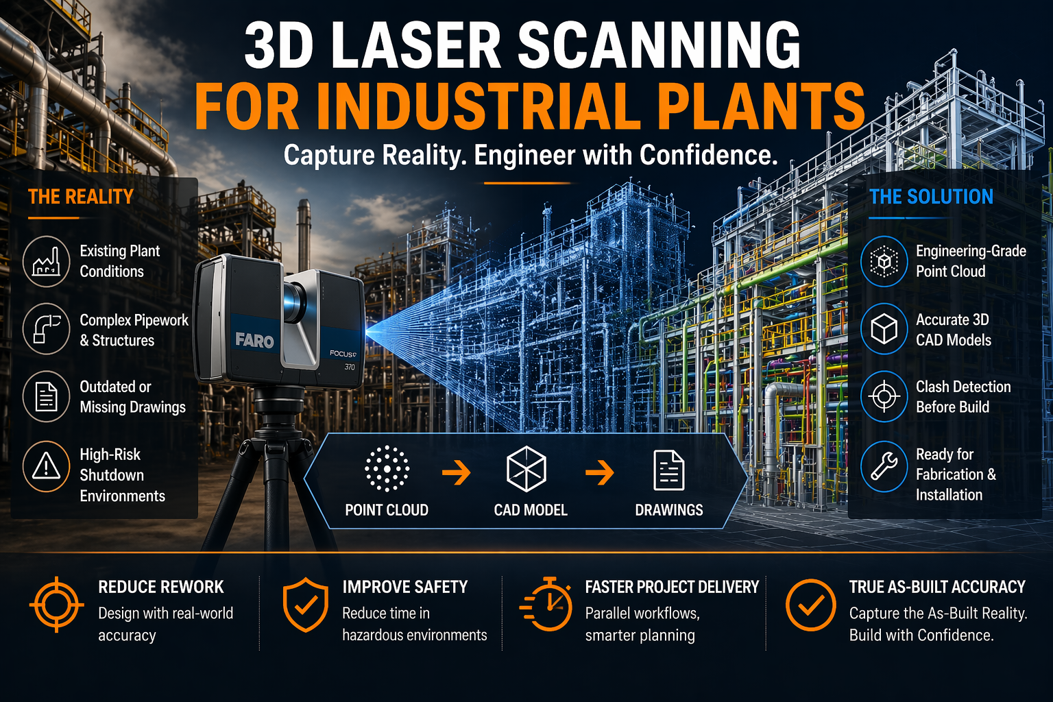
3D Laser Scanning for Industrial Plants

3D laser scanning for industrial plants

3D Laser Scanning for Industrial Plants | Hamilton By Design

Precision Capture. Smarter Engineering. Reduced Risk.

Blue 3D LiDAR scanner icon on a tripod with scanning waves

Industrial plants are complex, high-risk environments where accuracy is everything. Whether you’re working in mining, processing, manufacturing, or energy, one incorrect dimension can lead to costly rework, shutdown delays, or safety issues.

At Hamilton By Design, we specialise in 3D laser scanning for industrial plantsโ€”capturing real-world conditions with engineering-grade accuracy and turning them into usable models, drawings, and digital assets.


3D LiDAR scanning and 3D modelling service button โ€” laser scanner capturing a point cloud for engineering and CAD modelling
Mechanical engineering services

What is 3D Laser Scanning for Industrial Plants?

3D laser scanning (LiDAR) uses high-speed laser measurement technology to capture millions of points in spaceโ€”creating a point cloud that represents the exact geometry of your plant.

Unlike traditional measuring methods:

  • No manual tape measurements
  • No guesswork or assumptions
  • No reliance on outdated drawings

Instead, you get a true digital representation of reality.


Why Industrial Plants Need 3D Laser Scanning

1. Brownfield Accuracy

Most industrial facilities have evolved over time. Drawings rarely reflect whatโ€™s actually been built.

3D scanning provides:

  • Accurate as-built conditions
  • Clash detection before fabrication
  • Confidence in design decisions

2. Shutdown Planning & Risk Reduction

Shutdowns are expensive. Every hour matters.

With a full point cloud:

  • Work can be planned offsite
  • Fabrication can occur before shutdown
  • Installation becomes faster and safer

3. Complex Geometry Capture

Industrial plants include:

  • Dense pipework
  • Structural steel
  • Conveyor systems
  • Mechanical equipment

3D scanning captures all of itโ€”simultaneouslyโ€”with millimetre-level detail.


4. Engineering-Ready Deliverables

At Hamilton By Design, we donโ€™t just scanโ€”we engineer.

Typical outputs include:

  • Registered point clouds (.E57, .RCP)
  • 3D CAD models (STEP, Parasolid)
  • 2D drawings (AutoCAD layouts, sections, elevations)
  • Simplified models for coordination and fabrication

Point Cloud vs STL โ€“ Why It Matters

Many scanning providers deliver mesh files (STL), which are often:

  • Heavy and difficult to edit
  • Not dimensionally reliable
  • Not suitable for engineering workflows

We focus on point cloud to CAD workflows, ensuring:

  • Traceability back to real-world data
  • Editable, parametric models
  • Engineering-grade outputsโ€”not just visuals

Our Technology & Workflow

We utilise high-precision scanning systems such as the FARO Focus S70 to capture industrial environments efficiently and accurately.

Our workflow:

  1. Site scanning (minimal disruption)
  2. Point cloud registration & validation
  3. Engineering model development
  4. Drawing production & issue

We also support integration into platforms like SolidWorks and Autodesk ReCap Pro for seamless design workflows.


Real Benefits for Industrial Clients

  • Reduced rework โ€“ design with confidence
  • Faster project delivery โ€“ parallel workflows
  • Improved safety โ€“ less time in hazardous areas
  • Better communication โ€“ visual clarity across teams
  • Digital asset creation โ€“ foundation for digital twins

Applications Across Industry

Our 3D laser scanning services are used across:

  • Mining and mineral processing plants
  • Power stations and utilities
  • Manufacturing facilities
  • Oil & gas infrastructure
  • Water treatment plants

From conveyors and chutes to pump stations and structural steel upgradesโ€”we connect design to reality.


Why Hamilton By Design?

Weโ€™re not just scanning techniciansโ€”weโ€™re engineers.

That means:

  • We understand fabrication tolerances
  • We design for real-world installation
  • We deliver outputs that your team can actually use

Our focus is simple:
Accurate data โ†’ Better decisions โ†’ Successful projects


Hamilton By Design logo displayed on a blue tilted rectangle with a grey gradient background
3D CAD Modelling Australia service banner for Hamilton By Design

Get Started

If youโ€™re planning an upgrade, shutdown, or new installation within an existing plant, 3D laser scanning is no longer optionalโ€”itโ€™s essential.

Hamilton By Design provides reliable, engineering-grade 3D laser scanning for industrial plants across Australia.

Our clients

Contact us today to discuss your project and see how we can support your next job with precision and clarity.

Name
Would you like us to arrange a phone consultation for you?
Address
CHPP Engineering title graphic featuring bold white text reading "CHPP Engineering" centred on a blue rounded rectangle background.
Pipework Drafting title graphic featuring bold white text reading "Pipework Drafting" centred on a blue rounded rectangle background.
3D LiDAR Scanning for Engineering Projects title graphic featuring bold white text on a blue rounded rectangle background.

When You Donโ€™t Trust the Design โ€“ And Donโ€™t Know What Youโ€™re Getting

3D laser scanning Sydney Harbour Bridge and Opera House with point cloud overlay for engineering modelling and design verification

In industrial and mechanical projects, one of the most common โ€” and costly โ€” client concerns is simple:

โ€œI donโ€™t trust the designโ€ฆ and I donโ€™t really know what Iโ€™m going to get.โ€

It usually starts with an existing asset.

  • Old drawings that donโ€™t match reality
  • Missing documentation
  • Modifications made over time
  • Conflicting information between teams

At that point, every decision becomes a risk.


The Real Problem Isnโ€™t the Design โ€” Itโ€™s the Data

Most design issues donโ€™t come from bad engineers.

They come from bad inputs.

If your base information is wrong:

  • Models wonโ€™t fit
  • Steel wonโ€™t align
  • Pipework clashes on install
  • Fabrication needs rework

And suddenly, what looked like a solid design becomes a site problem.


3D LiDAR scanning and 3D modelling service button โ€” laser scanner capturing a point cloud for engineering and CAD modelling
Mechanical engineering services

What Clients Are Actually Searching For

When clients say they donโ€™t trust the design, theyโ€™re usually looking for:

  • point cloud to CAD conversion services
  • reverse engineering services
  • mechanical engineering models
  • engineering-grade verification

What they really mean is:

โ€œI need to know this will fit before I spend money building it.โ€


Step 1: Capture Reality โ€” Not Assumptions

The first step is removing uncertainty completely.

Using engineering-grade LiDAR scanning, you capture the real-world geometry of your asset โ€” not what the drawings say, but what actually exists on site.

This is where most projects go wrong:

  • Assumptions instead of measurements
  • Tape measures instead of full coverage
  • Missed geometry due to line-of-sight limitations

With proper scanning, you get:

  • Full spatial accuracy
  • Complete coverage
  • A true digital representation of your plant

Learn more: https://www.hamiltonbydesign.com.au/home/engineering-services/3d-scanning-sydney/


Step 2: Turn Data Into a Usable Engineering Model

A scan on its own isnโ€™t enough.

You need something your engineers and designers can actually use.

We convert point clouds into:

  • Clean 3D CAD models
  • Plant layouts
  • Mechanical assemblies
  • Structural frameworks

Not meshes. Not visuals.

Engineering models that support real design decisions.

Learn more: https://www.hamiltonbydesign.com.au/


Step 3: Design With Confidence

Once the model reflects reality, engineering becomes predictable again.

Now you can:

  • Design around real constraints
  • Eliminate clashes before site
  • Validate clearances and fitment
  • Reduce risk across the project

Learn more: https://www.hamiltonbydesign.com.au/


Step 4: Deliver Drawings That Actually Work on Site

This is where trust is either confirmed โ€” or lost.

With verified models behind them, drawings become:

  • Accurate
  • Buildable
  • Reliable for fabrication and install

This means:

  • Less rework
  • Faster installs
  • Fewer RFIs
  • Better project outcomes

Learn more: https://www.hamiltonbydesign.com.au/


From Uncertainty to Engineering Confidence

Most providers offer a piece of the puzzle.

  • Scanning only
  • Modelling only
  • Drafting only

The problem is โ€” gaps between those stages create risk.

At Hamilton By Design, we connect the full workflow:

Scan โ†’ Model โ†’ Design โ†’ Fabrication

So youโ€™re not left wondering:

  • Will this fit?
  • Are these drawings right?
  • What happens on site?

Instead, you get:

  • Confidence before fabrication
  • Accuracy before installation
  • Clarity before committing cost

Final Thought

If you donโ€™t trust the design, itโ€™s usually because you donโ€™t trust the data behind it.

Fix the data โ€” and the design follows.


Hamilton By Design
Engineering-led scanning, modelling, and design for real-world results.


Name
Would you like us to arrange a phone consultation for you?
Address

3D CAD Modelling Australia service banner for Hamilton By Design

Mechanical Engineering | Structural Engineering


Mining Infrastructure Design Discussions โ€“ SolidWorks and Industrial Engineering

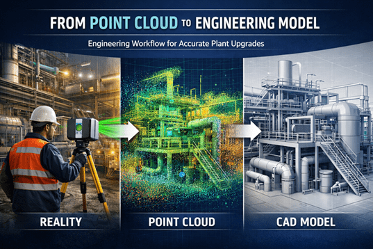
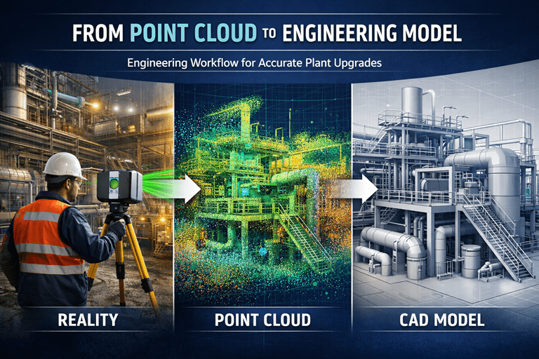
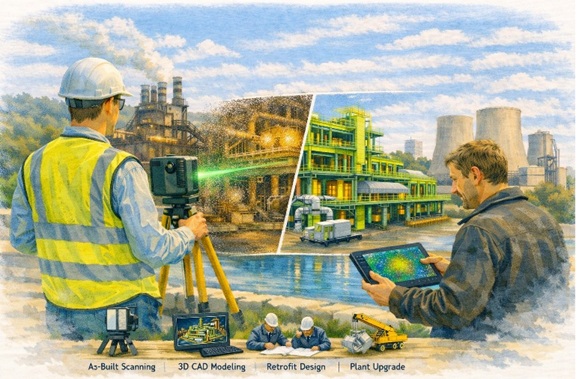
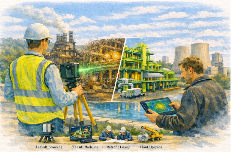
Engineering workflow showing industrial laser scanning, point cloud data, and a CAD model used for plant upgrade design.

Modern mining and industrial infrastructure projects increasingly rely on advanced digital engineering tools to support plant design, equipment upgrades, and infrastructure development. Engineers working in mining environments must often design and model complex systems including materials handling equipment, processing plant infrastructure, and structural steel frameworks.
Engineer using a laser scanner capturing an industrial facility, converting scan data into a point cloud and engineering CAD model.

One of the most commonly used design platforms for mechanical engineering and plant infrastructure modelling is SolidWorks, which allows engineers to develop detailed 3D assemblies and fabrication-ready engineering drawings.

At Hamilton By Design, many projects involve the integration of modern digital engineering workflows with practical industry experience. These workflows often include:

  • Mechanical design for mining infrastructure
  • Bulk materials handling system design
  • Industrial plant layout modelling
  • Point cloud modelling from laser scanning
  • Engineering design for plant upgrades and shutdown projects

Engineering Design in Mining Infrastructure

Mining infrastructure often includes complex systems such as conveyors, transfer stations, processing equipment, and plant structures. Designing or upgrading these systems requires accurate modelling of both existing infrastructure and proposed modifications.

Modern engineering teams frequently combine several technologies during the design process, including:

  • 3D laser scanning to capture existing plant conditions
  • Point cloud modelling to represent real-world infrastructure
  • CAD modelling using platforms such as SolidWorks
  • Engineering drawings and documentation for fabrication and construction

These tools allow engineers to develop more accurate designs and reduce risks when implementing plant modifications or shutdown upgrades.


Engineering Discussions and SolidWorks Design Examples

Engineering professionals often share practical insights, modelling approaches, and design workflows through technical blogs and engineering discussion platforms.

For those interested in SolidWorks modelling techniques, mining infrastructure design concepts, and materials handling engineering, additional discussions can be found on the following engineering blog:

Mining Infrastructure โ€“ SolidWorks Design
https://mininginfrastructuresolidworksdesign.blogspot.com/

The blog explores various topics including mechanical design workflows, industrial equipment modelling, and practical engineering approaches used when designing plant infrastructure.


Supporting Mining Engineering Projects

Hamilton By Design supports mining and industrial operators with engineering services that include mechanical design, infrastructure modelling, and reality capture technologies such as laser scanning.

Learn more about our engineering-grade scanning and modelling services:

Engineering-Grade 3D Laser Scanning for Mining and Industrial Projects
https://www.hamiltonbydesign.com.au/home/engineering-grade-3d-laser-scanning-mining-industrial/

3D Laser Scanning Across Australia
https://www.hamiltonbydesign.com.au/home/engineering-services/3d-laser-scanning/3d-laser-scanning-across-australia/

Capturing Existing Conditions Before Plant Upgrades
https://www.hamiltonbydesign.com.au/capture-existing-conditions-before-plant-upgrades/


3D LiDAR scanning and 3D modelling service button โ€” laser scanner capturing a point cloud for engineering and CAD modelling
Mechanical engineering services

Engineering Knowledge Sharing

Engineering blogs and technical discussion platforms provide an opportunity for engineers, designers, and industry professionals to share knowledge about real-world engineering challenges.

By combining practical industry experience with modern digital engineering tools, the mining and industrial sectors continue to improve the way infrastructure is designed, documented, and upgraded.

For more engineering discussions on SolidWorks design and mining infrastructure modelling, visit:

https://mininginfrastructuresolidworksdesign.blogspot.com

3D CAD Modelling Australia service banner for Hamilton By Design
Australian Drafting logo featuring bold white text reading "Australian Drafting" centred on a blue rounded rectangle background.
Engineering Governance title graphic featuring bold white text reading "Engineering Governance" centred on a blue rounded rectangle background.
Mechanical, Structural & Pipework Drafting service banner by Hamilton By Design featuring white text on a blue background.
Mechanical engineering services
Blue rounded button with the text โ€œSolidWorks Designโ€ in white.
Finite Element Analysis (FEA) engineering simulation button
3D LiDAR Scanning Darwin for engineering surveys, laser scanning, reality capture and point cloud modelling services
3D LiDAR Scanning Australia engineering services for laser scanning, reality capture, scan-to-CAD, Scan-to-BIM and as-built documentation across Australia
3D LiDAR scanning services on the Central Coast providing engineering-grade laser scanning, point cloud capture, scan-to-CAD modelling and industrial reality capture for infrastructure and industrial projects.
3D LiDAR Scanning Perth for engineering surveys, laser scanning, reality capture and point cloud modelling services
3D LiDAR Scanning Sydney for engineering surveys, laser scanning, reality capture and point cloud modelling services
3D LiDAR Scanning Brisbane for engineering surveys, laser scanning, reality capture and point cloud modelling services
3D LiDAR Scanning Canberra for engineering surveys, laser scanning, reality capture and point cloud modelling services
3D LiDAR Scanning Newcastle for engineering surveys, laser scanning, reality capture and point cloud modelling services
3D LiDAR Scanning Adelaide for engineering surveys, laser scanning, reality capture and point cloud modelling services

Industrial LiDAR Scanning & Retrofit Engineering โ€“ Pittsburgh, Pennsylvania

Industrial facility captured using 3D laser scanning for brownfield plant upgrade

Engineering Certainty in Legacy Industrial Facilities

Pittsburgh is not a new-build engineering market.

It is a modification market.

Steel mills, manufacturing plants, utilities and infrastructure in the Pittsburgh region have evolved over decades โ€” often across multiple owners, upgrades and undocumented changes. As a result, existing drawings rarely represent real conditions.

Hamilton By Design supports engineering and project teams by capturing accurate as-built data before modification work begins.

Rather than designing around assumptions, projects are developed from measured reality.


Engineer performing industrial LiDAR scan of a processing plant for retrofit design

Why Retrofit Projects in Pittsburgh Require LiDAR Scanning

Legacy facilities typically contain:

  • undocumented plant changes
  • relocated equipment
  • structural distortion over time
  • incomplete or missing drawings
  • congested services and pipework

When upgrades are designed from outdated information, installation conflicts occur and shutdown durations increase.

High-accuracy LiDAR scanning captures millions of measurement points and creates a true digital representation of the operating facility, reducing rework and unexpected site conflicts.


Typical Pittsburgh Projects We Support

Steel & Heavy Manufacturing

  • equipment replacement
  • access platforms and walkways
  • structural refurbishment
  • plant safety upgrades

Utilities & Processing Facilities

  • pipe routing modifications
  • pump and tank replacement
  • tie-in engineering
  • maintenance shutdown planning

Industrial Infrastructure & Brownfield Sites

  • facility upgrades
  • expansion works
  • mechanical retrofits
  • reverse engineering of existing equipment

Hamilton By Design combines engineering knowledge with reality capture to reduce fabrication and installation risk on operating assets.


Our Engineering-Led Workflow

(See full process: Industrial Retrofit LiDAR Scanning)

1 โ€” Site Capture

We collect high-density scan data without interrupting operations.

2 โ€” Digital As-Built Model

Point clouds are converted into coordinated engineering models.

3 โ€” Retrofit Design

Designs are developed directly from actual geometry.

4 โ€” Fabrication & Installation Confidence

Projects install correctly the first time, reducing shutdown risk.

Engineering-grade scanning enables clash detection, brownfield integration and efficient shutdown planning.


What Problems This Solves

For retrofit projects the largest risk is dimensional uncertainty.

Our workflow removes:

  • field modification work
  • fabrication rework
  • installation clashes
  • extended shutdown durations

Hamilton By Design focuses on reducing engineering and fabrication risk on existing industrial assets using accurate scan data and mechanical design integration.


Engineering-Led, Not Survey-Led

Many providers deliver point clouds.

We deliver engineering decisions.

One team is responsible from measurement through to design support โ€” ensuring the data collected is practical and usable for real construction outcomes.


Supporting Pittsburghโ€™s Ongoing Industrial Evolution

Regions like Pittsburgh continue to modernise existing infrastructure rather than replace it. Successful upgrades depend on understanding what is already built.

LiDAR scanning provides the digital foundation for safe modification, accurate fabrication and predictable installation.


Hamilton By Design logo displayed on a blue tilted rectangle with a grey gradient background

3D LiDAR scanning and 3D modelling service button โ€” laser scanner capturing a point cloud for engineering and CAD modelling
Mechanical engineering services

Talk to Hamilton By Design

If your project involves modifying an existing facility, engage scanning before design begins.

Design from reality โ€” not assumption.


Name
Would you like us to arrange a phone consultation for you?
Address

3D CAD Modelling Australia service banner for Hamilton By Design
Australian Drafting logo featuring bold white text reading "Australian Drafting" centred on a blue rounded rectangle background.
Engineering Governance title graphic featuring bold white text reading "Engineering Governance" centred on a blue rounded rectangle background.
Mechanical, Structural & Pipework Drafting service banner by Hamilton By Design featuring white text on a blue background.
Mechanical engineering services
Blue rounded button with the text โ€œSolidWorks Designโ€ in white.
Finite Element Analysis (FEA) engineering simulation button
3D LiDAR Scanning Darwin for engineering surveys, laser scanning, reality capture and point cloud modelling services
3D LiDAR Scanning Australia engineering services for laser scanning, reality capture, scan-to-CAD, Scan-to-BIM and as-built documentation across Australia
3D LiDAR scanning services on the Central Coast providing engineering-grade laser scanning, point cloud capture, scan-to-CAD modelling and industrial reality capture for infrastructure and industrial projects.
3D LiDAR Scanning Perth for engineering surveys, laser scanning, reality capture and point cloud modelling services
3D LiDAR Scanning Sydney for engineering surveys, laser scanning, reality capture and point cloud modelling services
3D LiDAR Scanning Brisbane for engineering surveys, laser scanning, reality capture and point cloud modelling services
3D LiDAR Scanning Canberra for engineering surveys, laser scanning, reality capture and point cloud modelling services
3D LiDAR Scanning Newcastle for engineering surveys, laser scanning, reality capture and point cloud modelling services
3D LiDAR Scanning Adelaide for engineering surveys, laser scanning, reality capture and point cloud modelling services

Identifying Fastener Threads in the Field

Metric vs American vs British Threads โ€” and the Australian Standards That Govern Them

In maintenance workshops and brownfield sites, one of the most common hidden problems is not bolt strength โ€” it is thread identification.

Equipment imported from the USA, Europe and the UK often ends up assembled together on Australian sites.
The bolts may look identical.
They may even screw together.

But they are not interchangeable.

Incorrect thread matching damages load capacity, prevents correct preload, and leads to loosening, fatigue cracking and eventual failure.

This guide explains the major fastening thread systems encountered in Australia (excluding pipe threads), how to recognise them, and the Australian Standards that apply.


1. The Three Fastener Thread Systems

There are three main fastening thread families encountered in mechanical and structural equipment:

SystemOriginThread AngleTypical Location
Metric ISOAustralia / Europe / modern equipment60ยฐMost modern machinery
Unified (UNC/UNF)USA60ยฐMining & imported plant
Whitworth (BSW/BSF/BA)UK / older Commonwealth55ยฐOlder equipment & legacy machinery

Even though UNC and Metric share a 60ยฐ angle, the pitch is different โ€” therefore they are not compatible.

Whitworth threads are particularly problematic because they will partially screw into metric or UNC holes before binding.


2. Metric Threads (ISO Metric โ€” Australian Standard Fasteners)

These are the primary fastening threads used in Australia.

(Coarse pitch series)

SizeMajor DiameterPitchMinor Diameter (approx)
M66.0 mm1.04.8 mm
M88.0 mm1.256.5 mm
M1010.0 mm1.58.2 mm
M1212.0 mm1.759.9 mm
M1616.0 mm2.013.8 mm
M2020.0 mm2.517.3 mm
M2424.0 mm3.020.8 mm

Fine pitch versions also exist for vibration and adjustment applications.

Typical Uses

  • Structural steel connections
  • Machinery assembly
  • Guards and access platforms
  • General engineering

3. Unified American Threads (UNC / UNF)

Common on imported mining and mobile equipment.

UNC โ€“ Coarse

SizeMajor DiameterPitch
1/4-206.35 mm1.27 mm
3/8-169.53 mm1.59 mm
1/2-1312.70 mm1.95 mm
3/4-1019.05 mm2.54 mm
1-825.40 mm3.18 mm

UNF โ€“ Fine

Used where vibration resistance is required.

Key Characteristic
UNC bolts will often start threading into metric holes but will not achieve correct preload.


4. British Threads (Whitworth Form)

Recognised by their 55ยฐ thread angle.

BSW โ€“ Coarse

SizeMajor DiameterPitch
1/4 BSW6.35 mm1.34 mm
3/8 BSW9.53 mm1.59 mm
1/2 BSW12.70 mm2.12 mm
3/4 BSW19.05 mm2.54 mm

BSF โ€“ Fine

Used historically in machinery.

BA Threads

Small instrumentation and electrical fasteners.

Typical Location

  • Pre-1980 plant
  • UK imported machinery
  • Electrical equipment

Why Incorrect Thread Matching Causes Failures

Threads do not primarily carry shear load โ€” they generate preload.

If pitch or angle differs:

  • preload is reduced
  • flank contact is uneven
  • joint loosens under vibration
  • fatigue cracking begins

Many failures blamed on vibration are actually incorrect thread engagement.


Field Identification Tips

ObservationLikely Thread
Marked M12Metric
Fraction size (1/2, 3/4)UNC/UNF or Whitworth
Smooth but tight engagementWrong pitch
Binds after 2 turnsWhitworth vs Metric

Thread gauge confirmation is always recommended.


Australian Standards Relating to Fastener Threads

Metric Thread Geometry

AS 1721 โ€” General purpose metric screw threads
AS 1275 โ€” Metric screw threads for fasteners

Fastener Product Standards

AS 1110 โ€” Metric hex bolts and screws
AS 1111 โ€” Commercial hex bolts and screws
AS 1112 โ€” Hexagon nuts
AS 1420 โ€” Socket head cap screws

Mechanical Properties

AS/NZS 4291.1 โ€” Mechanical properties of bolts, screws and studs
AS/NZS 4291.2 โ€” Mechanical properties of nuts
ISO 898-1 / ISO 898-2 โ€” Adopted strength properties
ISO 3506 โ€” Stainless steel fasteners

Structural Bolting

AS/NZS 1252 โ€” High strength structural bolting assemblies
AS 4100 โ€” Steel structures design
AS/NZS 5131 โ€” Fabrication and erection of structural steel

Coatings and Fit Allowances

AS/NZS 1214 โ€” Galvanised coatings on threaded fasteners
AS/NZS 4680 โ€” Hot dip galvanising
AS 2312.2 โ€” Corrosion protection guide
AS 1897 โ€” Electroplated coatings

3D LiDAR scanning and 3D modelling service button โ€” laser scanner capturing a point cloud for engineering and CAD modelling
Mechanical engineering services
Name
Would you like us to arrange a phone consultation for you?
Address

3D CAD Modelling Australia service banner for Hamilton By Design
3D LiDAR scanning and 3D modelling service button โ€” laser scanner capturing a point cloud for engineering and CAD modelling
Mechanical engineering services
Mechanical drafting services button
Blue rounded button with the text โ€œSolidWorks Designโ€ in white.
Blue banner graphic displaying the text "Point Cloud to CAD - Australia" in large white lettering, representing point cloud processing, scan-to-CAD conversion and digital engineering services across Australia.
Mechanical, Structural & Pipework Drafting service banner by Hamilton By Design featuring white text on a blue background.
Engineering Governance title graphic featuring bold white text reading "Engineering Governance" centred on a blue rounded rectangle background.
Mining Plant Upgrades promotional graphic with bold white text on a blue background representing mining infrastructure, plant improvement, and engineering upgrade projects.
3D Pipework promotional graphic with bold white text on a blue background representing pipework design, modelling, drafting, and engineering services.
Australian Drafting logo featuring bold white text reading "Australian Drafting" centred on a blue rounded rectangle background.
3D Pipework promotional graphic with bold white text on a blue background representing pipework design, modelling, drafting, and engineering services.
Mining Plant Upgrades promotional graphic with bold white text on a blue background representing mining infrastructure, plant improvement, and engineering upgrade projects.
3D LiDAR Scanning for Engineering Projects title graphic featuring bold white text on a blue rounded rectangle background.
Australian Drafting logo featuring bold white text reading "Australian Drafting" centred on a blue rounded rectangle background.
Engineering Governance title graphic featuring bold white text reading "Engineering Governance" centred on a blue rounded rectangle background.
Mechanical, Structural & Pipework Drafting service banner by Hamilton By Design featuring white text on a blue background.
Mechanical engineering services
Blue rounded button with the text โ€œSolidWorks Designโ€ in white.
Finite Element Analysis (FEA) engineering simulation button

Mechanical Engineering | Structural Engineering