Design Verification Under AS 4991

Engineer verifying lifting beam design under AS 4991 with FEA stress analysis overlay in fabrication workshop.

Design Verification Under AS 4991: What Fabricators Often Miss

In Australiaโ€™s heavy industry and mining sectors, lifting devices are routinely fabricated under AS 4991 โ€“ Lifting Devices.

While most fabricators understand the need for compliance, design verification is the area where projects most commonly fall short.

The result?
Rework, certification delays, client rejection, and exposure to liability.

Letโ€™s look at what is often missed โ€” and how to avoid it.


What AS 4991 Actually Requires

AS 4991 does not simply require a fabricated lifting device to be โ€œstrong enough.โ€ It requires:

  • Engineered design calculations
  • Verification of limit states
  • Weld design compliance
  • Traceable material selection
  • Independent design review (where applicable)
  • Documentation suitable for certification

Fabrication alone does not equal compliance.
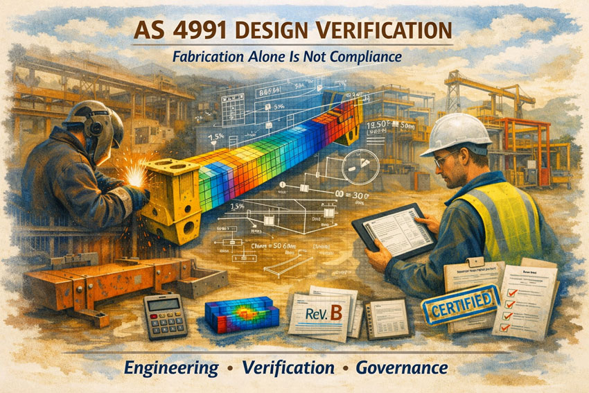

AS 4991 design verification process showing fabrication, engineering analysis and certification workflow.

Engineering Calculations That Donโ€™t Match the Fabrication

One of the most common issues is a disconnect between:

  • The engineered design intent
  • The shop drawings
  • The fabricated outcome

Changes made โ€œon the floorโ€ โ€” such as:

  • Plate thickness substitutions
  • Weld size adjustments
  • Lug geometry tweaks
  • Hole size changes

โ€” can invalidate the original engineering verification.

Without re-verification, certification becomes compromised.


Weld Design is Assumed โ€” Not Verified

Fabricators often focus on structural members but overlook:

  • Fillet weld capacity under combined loading
  • Fatigue considerations
  • Load directionality
  • Throat thickness assumptions

AS 4991 compliance requires welds to be engineered โ€” not assumed.

This is particularly critical in:

  • Spreaders
  • Lifting beams
  • Trunnions
  • Custom lifting frames

No Formal Design Review or Independent Check

The standard requires appropriate verification.

This may include:

  • Independent engineering review
  • Check calculations
  • Formal sign-off by a competent engineer

A workshop โ€œreviewing its own drawingsโ€ does not satisfy independent verification.


Load Cases Are Underestimated

Another common oversight is failure to account for:

  • Dynamic factors
  • Off-centre loading
  • Sling angles
  • Shock loading
  • Environmental factors

Lifting devices rarely operate under perfect static conditions.

Design verification must reflect real-world application.


Documentation Gaps

Even when the engineering is sound, documentation is often incomplete:

  • No clear calculation pack
  • No revision control
  • No traceable material certificates
  • No weld procedure documentation
  • No inspection and test plan

Without structured documentation, clients and auditors may reject otherwise adequate equipment.

This is where governance becomes as important as engineering.


Why This Matters

Failure in lifting devices carries:

  • Serious safety risk
  • Legal liability
  • Project shutdowns
  • Insurance exposure

Under Australian WHS law, the duty of care extends beyond fabrication โ€” it includes engineering adequacy.

AS 4991 is not a box-ticking exercise. It is a risk mitigation framework.


The Hamilton By Design Approach

At Hamilton By Design, we support fabricators by providing:

  • Independent design verification
  • Engineering calculation packages
  • Weld capacity review
  • Load case validation
  • Documentation structured for audit readiness
  • Revision-controlled drawing governance

We work alongside workshops โ€” not against them โ€” ensuring compliance before equipment reaches site.

The cost of early verification is small compared to rework, rejected certification, or liability exposure.



3D LiDAR scanning and 3D modelling service button โ€” laser scanner capturing a point cloud for engineering and CAD modelling
Mechanical engineering services

Final Thought

If your lifting device cannot withstand engineering scrutiny on paper, it should not be trusted in the air.

AS 4991 compliance is not about fabrication skill alone โ€” it is about verified engineering intent.

If you would like assistance reviewing your lifting device designs or establishing a verification framework, reach out to the Hamilton By Design team.



Name
Would you like us to arrange a phone consultation for you?
Address

3D CAD Modelling Australia service banner for Hamilton By Design
Finite Element Analysis (FEA) engineering simulation button
Mechanical engineering services

Australian Standards That Shape Engineering, Scanning & Documentation Projects

Australian Standards play a critical role in how engineering, design, and construction work is delivered โ€” particularly on industrial, mining, power, and brownfield projects where safety, reliability, and compliance matter.

At Hamilton By Design, engineering services, 3D scanning, CAD modelling, and as-built documentation are delivered with a clear understanding of how Australian Standards inform real-world engineering decisions. Rather than treating standards as a checklist, they are applied as part of a practical, engineering-led workflow.


Why Australian Standards matter in real projects

Australian Standards exist to ensure that structures, equipment, and systems are:

  • Safe to build, operate, and maintain
  • Fit for their intended purpose
  • Designed and documented consistently
  • Defensible if designs are reviewed or audited

On existing sites, outdated drawings and undocumented modifications make standards-based assessment even more important. Accurate data, clear documentation, and sound engineering judgement are essential to applying standards correctly.


Key Australian Standards referenced across our work

The following Australian Standards are commonly referenced across Hamilton By Design projects and content, particularly where engineering, scanning, drafting, and compliance intersect.


AS 1657 โ€“ Fixed platforms, walkways, stairways and ladders

This standard governs access systems used for operation and maintenance.

It is frequently applied when:

  • Assessing existing platforms and walkways
  • Designing upgrades or retrofits
  • Verifying clearances, handrails, and access geometry

Engineering-grade as-built information is often required to accurately assess compliance on existing sites.


AS 3990 โ€“ Mechanical equipment steelwork

AS 3990 applies to steelwork that supports mechanical equipment.

It is commonly referenced for:

  • Equipment support frames
  • Plant steelwork and interfaces
  • Integration of access systems with equipment

Accurate geometry and documentation are essential when modifying or extending existing steelwork.


AS 4100 โ€“ Steel structures

AS 4100 forms the basis for the design and assessment of steel structures.

This standard is applied to:

  • Structural steel framing
  • Platforms, walkways, and support structures
  • Structural upgrades and strengthening works

Structural engineering decisions rely on accurate understanding of existing member sizes, connections, and load paths.


AS 4991 โ€“ Lifting devices

AS 4991 covers the design and use of lifting devices.

It is relevant when:

  • Designing or modifying lifting points
  • Documenting lifting arrangements
  • Assessing existing lifting equipment

Clear engineering documentation supports safe lifting operations and ongoing compliance.


AS 4024 โ€“ Safety of machinery

AS 4024 relates to machinery safety and risk control.

It is typically referenced where:

  • Machinery interfaces with structures or access systems
  • Guarding or safety systems are affected by modifications
  • Engineering changes may impact operator safety

AS 1100 โ€“ Technical drawing (implied through documentation workflows)

AS 1100 governs technical drawing conventions.

While not always referenced explicitly, it underpins:

  • Engineering drawings
  • Structural and mechanical drafting
  • As-built documentation

Clear, standardised drawings are essential for construction, fabrication, and future asset modifications.


National Construction Code (NCC)

The NCC provides a regulatory framework for building compliance.

Engineering and documentation workflows often support:

  • Existing building upgrades
  • Compliance verification
  • Safety-in-design obligations

Accurate as-built documentation helps ensure engineering decisions align with NCC requirements.


The role of 3D scanning and as-built data in standards-based engineering

Australian Standards often require engineers to understand what actually exists on site, not just what is shown on legacy drawings.

Engineering-grade 3D laser scanning and LiDAR are used to:

  • Capture accurate geometry of existing assets
  • Identify undocumented modifications
  • Support standards-based assessment and design
  • Produce reliable as-built documentation

This is particularly important on brownfield and live sites where assumptions introduce risk.


Applying standards with engineering judgement

Australian Standards do not replace engineering judgement โ€” they rely on it.

Effective application of standards requires:

  • Accurate site information
  • Understanding of real operating conditions
  • Clear documentation of assumptions and limitations
  • Coordination between engineering, drafting, and construction

This is why standards, scanning, drafting, and engineering must work together as part of a single workflow.


Our clients:


Final thoughts

Australian Standards provide the framework for safe and compliant engineering, but outcomes depend on how they are applied.

By combining engineering expertise with accurate data capture and clear documentation, standards can be applied confidently โ€” reducing risk, improving safety, and delivering better long-term asset performance.


Hamilton By Design logo displayed on a blue tilted rectangle with a grey gradient background
3D LiDAR scanning and 3D modelling service button โ€” laser scanner capturing a point cloud for engineering and CAD modelling
Mechanical engineering services

Need standards-aware engineering support?

If your project involves upgrades, existing assets, or compliance-driven design, engineering-led scanning, drafting, and documentation can make all the difference.

Hamilton By Design supports projects where Australian Standards, engineering judgement, and real-world conditions must align.

Name
Would you like us to arrange a phone consultation for you?
Address
Finite Element Analysis (FEA) engineering simulation button
Mechanical engineering services

Structural Drafting Software Is Only as Good as the Engineering Behind It

Engineer operating an engineering-grade LiDAR scanner to capture an industrial steel structure for structural drafting and fabrication documentation

Structural Drafting Software โ€” Why Engineering Leadership Matters

Structural drafting underpins how assets are designed, reviewed, fabricated, and built. While there is no shortage of powerful drafting software on the market, successful project outcomes are not defined by software alone โ€” they are defined by engineering judgement applied through the right tools.

At Hamilton By Design, we operate across multiple structural drafting platforms to suit asset risk, fabrication pathways, and project complexity. Below are the five most widely used structural drafting software platforms in industry today โ€” and how they fit into an engineering-led workflow.


AutoCAD โ€” The Industry Baseline for Structural Drafting

AutoCAD remains the most widely accepted platform for 2D structural drafting across Australia.

It is commonly used for:

  • General arrangement drawings
  • Structural sections and details
  • Retrofit and brownfield documentation
  • As-built drawings

AutoCADโ€™s strength lies in its universality and clarity, particularly for issuing IFC documentation. However, on complex or fabrication-heavy projects, AutoCAD alone relies heavily on the experience and discipline of the engineer and drafter producing the drawings.


Revit โ€” Coordinated Structural Documentation in a BIM Environment

Revit enables a model-driven approach to structural drafting, where plans, sections, elevations, and schedules are generated from a single coordinated model.

It is well suited to:

  • Building structures
  • Multidiscipline coordination
  • Projects requiring digital handover or asset information models

While Revit is a powerful coordination tool, its effectiveness depends on engineering control of modelling assumptions, member sizing, and load paths. Without that oversight, models can appear complete while concealing risk.


Engineering-led LiDAR scanning of an industrial steel platform to produce accurate structural drafting data

Tekla Structures โ€” Fabrication-Level Structural Drafting

Tekla Structures is widely recognised as the benchmark platform for steel and concrete detailing.

It is commonly used where:

  • Fabrication accuracy is critical
  • Connection design must be unambiguous
  • CNC data, BOMs, and shop drawings are required

Tekla excels in mining, heavy industry, and complex steel structures where what is modelled is what gets built. Its strength is not simply its software capability, but its ability to enforce constructability and clarity.


Advance Steel โ€” Steel Detailing Within an AutoCAD Environment

Advance Steel extends traditional AutoCAD workflows into 3D steel detailing.

It is often selected where:

  • Fabricators operate primarily in AutoCAD
  • 3D steel modelling is required without a full BIM transition
  • Fabrication drawings and NC data are needed

Advance Steel provides an efficient pathway from drafting to fabrication when applied within an engineering-controlled workflow.


Our clients:


SolidWorks โ€” Structural Drafting for Industrial and Mechanical Assets

SolidWorks is widely used for industrial structures integrated with mechanical equipment.

It is particularly effective for:

  • Platforms, frames, skids, and support structures
  • Conveyors and transfer stations
  • Structures requiring integration with machinery and FEA

For industrial environments, SolidWorks enables structural drafting to be developed in context, reducing interface risk between mechanical and structural elements.


Software Is a Tool โ€” Engineering Is the Outcome

No single software platform is โ€œbestโ€ in all circumstances. Each has strengths depending on:

  • Asset type
  • Fabrication method
  • Risk profile
  • Compliance requirements

The real differentiator is engineering leadership โ€” selecting the right platform, applying the correct standards, and ensuring drawings are fit-for-purpose and fit-for-fabrication.


Hamilton By Design logo displayed on a blue tilted rectangle with a grey gradient background


3D LiDAR scanning and 3D modelling service button โ€” laser scanner capturing a point cloud for engineering and CAD modelling
Mechanical engineering services

Structural Drafting Done Properly

At Hamilton By Design, structural drafting is delivered as part of an engineering-led service, not a drafting-only output. Our work is supported by:

  • Engineering-grade 3D LiDAR scanning
  • Fabrication-ready documentation
  • Australian Standards-aligned detailing
  • Clear accountability from concept through to construction

If your project requires structural drafting that stands up to fabrication, construction, and long-term operation, we can help.


Need Structural Drafting Support?

If youโ€™re planning a new structure, upgrading an existing asset, or preparing fabrication documentation, contact Hamilton By Design to discuss how an engineering-led drafting approach can reduce risk and improve outcomes.

Name
Would you like us to arrange a phone consultation for you?
Address
Finite Element Analysis (FEA) engineering simulation button
Mechanical engineering services

AS 3990 Mechanical Equipment Steelwork | Walkways, Platforms & Conveyor Structures

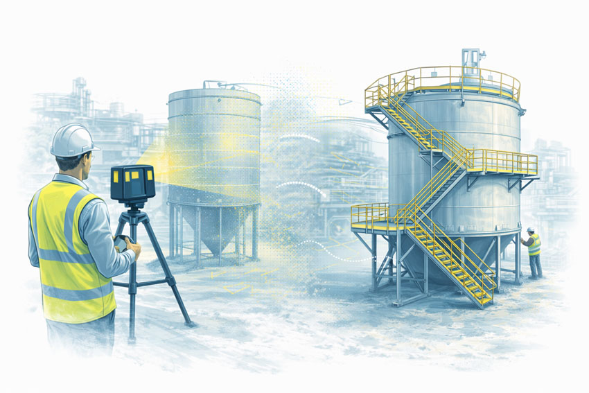
Engineer using LiDAR scanner to capture as-built tank steelwork, transitioning to compliant AS 3990 walkways and access platforms

AS 3990 โ€“ Mechanical Equipment Steelwork

Walkways, Conveyor Structures, Platforms and Gantries

Mechanical equipment steelwork is everywhere in industrial sites โ€” conveyor structures, access walkways, maintenance platforms, gantries and support frames. Over time, these structures are modified, loaded differently, repaired, and upgraded. Thatโ€™s where AS 3990 โ€“ Mechanical equipment โ€“ Steelwork becomes critical: it provides a framework for designing and verifying steelwork that supports mechanical equipment and associated access systems.

At Hamilton By Design, we help asset owners and project teams reduce risk by converting real as-built steelwork into engineering-grade digital models that can be checked, upgraded, and documented with confidence.


3D LiDAR scanning of industrial tank steelwork showing as-built condition and engineered walkways and stairs designed to AS 3990

When AS 3990 Steelwork Becomes a Problem in the Real World

Steelwork rarely fails because it was โ€œobviously wrongโ€ on day one. The most common issues develop gradually due to changes in loading, upgrades, corrosion, or incomplete documentation.

Common triggers we see on site

  • New conveyor drives, chutes, skirts, guards, or pull-wire systems added after commissioning
  • Extra services added: cable trays, hose reels, water lines, pipework, and supports
  • Walkway changes for access, maintenance, or guarding upgrades
  • Localised damage from impact, vibration, or operational fatigue
  • Corrosion or section loss in wash-down areas, coastal environments, or chemical exposure zones
  • Legacy steelwork with missing drawings or unknown load assumptions

If you canโ€™t prove what exists (accurately), it becomes difficult to prove compliance, fitness-for-purpose, or due diligence.


Key Engineering Risks with Walkways, Platforms, Gantries and Conveyor Structures

1) Design intent vs as-built reality

Many sites have steelwork that differs from drawings due to shutdown modifications or brownfield constraints. Small deviations in member size, connection detailing, or geometry can materially change structural performance.

2) Loads have changed โ€” but the steelwork didnโ€™t

A โ€œsimpleโ€ modification can add significant load: added services, heavier equipment, changed maintenance practices, or multiple personnel working in the same bay. These changes can push members or connections beyond the original assumptions.

3) Conveyor vibration and dynamic effects

Conveyor structures experience cyclic loading, start/stop effects, and vibration. Even if the structure looks acceptable, fatigue and resonance can become a long-term reliability problem โ€” particularly around drive stations, transfer points, and cantilevered platforms.

4) Connection adequacy often governs

Field-welded brackets, modified gussets, bolt slip, corroded fasteners, and non-standard connection geometry can become the weak link. Connection performance is frequently the true limiting factor in older or heavily modified steelwork.

5) Access and safety interfaces

Walkways and platforms often sit at the intersection of multiple requirements: safe access geometry, handrails, toe-boards, gates, and guarding. If access steelwork was modified without a proper verification step, the risk becomes both structural and safety-related.


What โ€œVerificationโ€ Looks Like in Practice

AS 3990 steelwork compliance is not just a box-tick. In a practical project environment, it means you can answer:

  • What steelwork exists right now (as-built)?
  • What loads and operational conditions apply today (not ten years ago)?
  • Are members and connections adequate under realistic scenarios?
  • What upgrades are required, and can they be fabricated to fit first time?
  • Can the asset owner document compliance and risk controls for governance?

Hamilton By Design supports this process by bringing LiDAR scanning + mechanical engineering + fabrication-ready outputs together under one roof.


How Hamilton By Design Helps (Our Typical Deliverables)

1) Engineering-grade 3D LiDAR scanning of steelwork

We capture accurate geometry of:

  • Walkways and access platforms
  • Conveyor stringers, trestles, and transfer towers
  • Gantries, monorails, and maintenance frames
  • Supports, bracing, ladders, stairs, and access interfaces

Related service:
3D Laser Scanning: https://www.hamiltonbydesign.com.au/3d-laser-scanning/

2) As-built CAD model for verification and design

We convert the scan into usable engineering outputs such as:

  • As-built 3D CAD models
  • Key dimensions, levels, and clearances
  • Interference checking and fit-up planning
  • Fabrication-ready drawings for retrofit steelwork

3) Engineering checks and upgrade design

Where required, we support structural verification and upgrade design using engineering workflows suited to brownfield assets.

Related capability:
SolidWorks FEA / simulation workflows: https://www.hamiltonbydesign.com.au/home/solidworks/solidworks-fea-simulation/


Where This Matters Most (Typical Applications)

  • Conveyor upgrades and transfer station modifications
  • Walkway widening, new stair access, and maintenance platform additions
  • Guarding upgrades, pull-wire additions, and access compliance programs
  • Corrosion repairs and local strengthening
  • Brownfield plant modifications with limited shutdown time
  • Audit readiness and engineering documentation clean-up

If youโ€™re working around conveyors, you may also find this relevant:
AS 1755 Conveyor Safety: https://www.hamiltonbydesign.com.au/as-1755-conveyor-safety/

And for safety leadership context:
Machine guarding lessons: https://www.hamiltonbydesign.com.au/machine-guarding-in-australia-a-decade-of-lessons-for-leaders-asset-owners-and-engineers/


Standards and Compliance Context (How AS 3990 Fits In)

AS 3990 typically sits alongside a broader compliance context depending on the asset and scope. In many industrial environments, it may interact with standards and guidance such as:

  • AS 1657 (fixed platforms, walkways, stairways and ladders)
  • AS 4100 (steel structures)
  • AS/NZS 1170 (structural actions / loading)
  • AS 1755 (conveyor safety and associated interfaces)

For official sources and governance context:

(Note: Always confirm the current revision and applicability of standards for your site, scope, and jurisdiction.)


Why Digital As-Built Matters for AS 3990 Steelwork

A verified as-built model reduces:

  • Upgrade risk and fabrication rework
  • Shutdown time lost to unexpected clashes
  • Safety risks from undocumented modifications
  • Compliance gaps during audits and governance reviews

It also supports โ€œfit-first-timeโ€ fabrication because designers, engineers, and fabricators are working from the same geometry โ€” not assumptions.


Talk to an Engineer About Your AS 3990 Steelwork

If youโ€™re planning an upgrade, responding to an audit, or unsure whether existing walkways, platforms, gantries or conveyor structures still meet their intended duty, we can help you quickly establish a reliable baseline.

Start with scanning, modelling, and engineering verification โ€” and build from facts.

Related service pages to explore:

Hamilton By Design logo displayed on a blue tilted rectangle with a grey gradient background
3D LiDAR scanning and 3D modelling service button โ€” laser scanner capturing a point cloud for engineering and CAD modelling
Mechanical engineering services

Our clients:

Name
Would you like us to arrange a phone consultation for you?
Address
https://youtu.be/jOGYoLL1Vro?si=vPkEAPQiFzB9fd6-

Mechanical Engineering | Structural Engineering


Product Enviro Impact Studies

Product โ€” Environmental Impact & Material Studies

Engineering insight for sustainable, low-impact mechanical design

At Hamilton By Design, we help clients make informed, measurable decisions about the environmental impact of their products and engineered components. Using SolidWorks Sustainability tools, lifecycle data and practical engineering analysis, we provide consulting studies that reduce material usage, lower embodied carbon, and improve the long-term footprint of mechanical designs.

Whether you’re developing a new product, upgrading a mechanical system, or aligning with ESG requirements, we offer clear, engineering-led sustainability assessments that turn environmental goals into real design decisions.


Why Environmental Impact & Material Studies Matter

Sustainability is no longer optional โ€” clients, fabricators, operators and regulators increasingly expect engineering solutions to be:

  • Material-efficient
  • Energy-efficient
  • Low carbon
  • Durable and maintainable
  • Optimised for the product lifecycle

Traditional mechanical design focuses on strength, manufacturability and cost.
Our sustainability studies add a fourth dimension:

How does this design affect the environment across its entire lifecycle?

By integrating sustainability early, you reduce waste, improve product performance, and demonstrate responsible engineering โ€” without compromising reliability.


What We Analyse

Using SolidWorks Sustainability and lifecycle datasets, we assess four key environmental indicators:

1. Carbon Footprint (COโ‚‚-e)

The greenhouse gas emissions generated from raw material extraction through manufacturing, transport and end-of-life.

2. Energy Consumption

Total energy required to produce and process materials and manufacture the component.

3. Water Consumption

Water usage attributed to material production and lifecycle transformation.

4. Air & Water Pollution Impacts

Environmental impacts associated with material processing and waste streams.

These metrics can be compared across multiple design options, materials or fabrication methods.


Our Consulting Approach

Our work goes beyond software output โ€” we interpret results as engineers and provide actionable guidance.

1. Define the Product, Materials & Duty

We begin by understanding the productโ€™s:

  • Function
  • Load case and duty cycle
  • Required design life
  • Operational environment
  • Manufacturing methods

This ensures recommendations never compromise performance.

2. Benchmark the Current Design

We run a baseline sustainability assessment using:

  • Current material
  • Current thickness or geometry
  • Current manufacturing processes

This gives a measurable starting point.

3. Explore Material Alternatives

We compare:

  • Steel grades
  • Stainless types
  • Aluminium alloys
  • Composites and engineered materials

Each option is evaluated on both environmental impact and mechanical suitability.

4. Structural & Weight Optimisation

Where possible, we explore options such as:

  • Thickness reduction
  • Stiffening strategies
  • Alternative load paths
  • Topology optimisation
  • Reduced weld lengths or simplified fabrication

These refinements can significantly reduce material usage.

5. Lifecycle & End-of-Life Considerations

We review recyclability, expected maintenance intervals, and the long-term sustainability profile of the design.

6. Provide Evidence-Based, Buildable Recommendations

Our final studies deliver clear, practical direction โ€” not just graphs:

  • Which materials are most sustainable and still fit for purpose
  • What geometric changes reduce impact without adding fabrication complexity
  • How much carbon reduction is achievable using simple redesign decisions
  • Opportunities for long-term lifecycle improvement

Typical Deliverables

Depending on the project scope, we provide:

  • Sustainability Report (PDF) summarising:
    • Carbon footprint
    • Energy use
    • Water consumption
    • Environmental impact indices
  • Comparative study of design options and materials
  • Bill of Materials analysis showing material contribution to total impact
  • Optimisation recommendations with quantified benefits
  • CAD model updates incorporating approved design improvements
  • Lifecycle assessment notes for ESG documentation or tender submissions

Reports are formatted for presentation to management, regulators or client stakeholders.


Where This Service Adds the Most Value

Environmental impact & material studies are ideal for:

  • New product development
    • Embedding sustainability requirements from day one
  • Mining and industrial equipment upgrades
    • Reducing steel usage, weight, and fabrication footprint
  • Tender or compliance requirements
    • Demonstrating environmental responsibility with data-backed evidence
  • Corporate ESG objectives
    • Supporting sustainability reporting and engineering governance
  • Cost-saving engineering
    • Material optimisation often lowers fabrication cost as well as environmental impact

Why Work With Hamilton By Design?

  • Engineer-led sustainability analysis โ€” combining mechanical design expertise with lifecycle data
  • SolidWorks Sustainability integrated directly into our CAD workflow
  • Practical, buildable recommendations, not theoretical optimisation
  • Strong mechanical engineering roots โ€” ensuring sustainability never compromises safety or performance
  • Experience across mining, industrial and manufacturing sectors
  • Clear communication and documentation tailored for both technical and non-technical stakeholders

Sustainability is not just a checkbox โ€” itโ€™s a smarter way to engineer.


Hamilton By Design logo displayed on a blue tilted rectangle with a grey gradient background
3D LiDAR scanning and 3D modelling service button โ€” laser scanner capturing a point cloud for engineering and CAD modelling
Mechanical engineering services

Letโ€™s Improve the Environmental Impact of Your Product

If you want to reduce material use, demonstrate environmental responsibility, or simply design smarter, Hamilton By Design can help you make informed decisions backed by real engineering analysis.

Contact us to discuss your Product โ€” Environmental Impact & Material Study, or integrate this service with:

  • Mechanical Design & Custom Equipment Layouts
  • 3D CAD Modelling & Mechanical Drafting
  • Industrial Machinery & Plant Systems Design
  • FEA & Mechanical/Structural Assessment

Weโ€™re ready to help you build products that perform โ€” and tread lighter on the environment.

Email โ€“ [email protected]

Phone โ€“ (+61) 0477 002 249

Our Clients

Name
Would you like us to arrange a phone consultation for you?
Address

Mechanical Engineering | Structural Engineering

Lessons from a Landmark Case

Finite Element Analysis (FEA) engineering simulation button
Mechanical engineering services

SolidWorks FEA Simulation

SolidWorks FEA Simulation

At Hamilton By Design, we use SolidWorks Simulation FEA to help mining, manufacturing, power generation and industrial clients make better decisions before anything is cut, welded or installed.

Whether youโ€™re upgrading a chute, checking a pressure vessel, or validating a complex brownfield retrofit, our team can simulate real-world loads, temperatures and constraints so you know how your design will behave in service.


Why use SolidWorks FEA with Hamilton By Design?

  • Mechanical engineers with real site experience โ€“ CHPPs, conveyors, reclaimers, pressure vessels, structures and plant equipment.
  • Seamless link to 3D CAD โ€“ we model in SolidWorks, analyse in SolidWorks Simulation, then deliver fabrication-ready drawings.
  • Engineering-grade results โ€“ correct boundary conditions, meshing control and code-aligned assessment where required.
  • Clear reports for decision-makers โ€“ not just stress plots, but explanations, factors of safety and practical recommendations.

Our SolidWorks FEA Capabilities

We offer a broad range of analysis types, from straightforward linear static checks through to advanced contact, thermal and fatigue studies.

1. Linear Static & Structural Integrity

For components and assemblies under static loading:

  • Linear Static (parts and assemblies)
  • Linear Static โ€“ multi-body assemblies
  • Beam and Shell element models for frames, platforms, platework and tanks
  • Static Stress (parts)
  • Static Stress (assemblies)
  • Contacts and contact sets (bonded, no-penetration, friction etc.)
  • Large displacement behaviour for flexible or slender structures

Typical use cases:

  • Platforms, walkways, supports, frames
  • Brackets, bases, machine frames and guarding
  • Brownfield modifications and tie-ins

2. Modal, Frequency & Buckling Analysis

Understanding how structures respond to vibration and instability:

  • Frequency / Modal analysis
  • Modal / Frequency analysis (eigenfrequencies and mode shapes)
  • Buckling Analysis (eigenvalue / linear buckling)
  • Modal / Buckling studies for slender structures

Typical use cases:

  • Avoiding resonance in platforms, ducts, chutes and pipework
  • Screening structures against equipment running speeds
  • Checking risk of buckling under compressive loads

3. Thermal Analysis (Steady & Transient)

Thermal loading can be just as critical as mechanical loading. We perform:

  • Steady State Thermal analysis
  • Transient Thermal analysis
  • Coupled thermalโ€“stress workflows (temperature โ†’ stress)

Typical use cases:

  • Hot chutes, ducts, kilns and enclosures
  • Equipment in high-temperature environments
  • Evaluating thermal gradients prior to stress assessment

4. Fatigue & Life Estimation

Assessing how long components are likely to last under cyclic loading:

  • Fatigue analysis using Stress-Life (SN curves)
  • Fatigue Analysis / Fatigue (SN Curves)
  • Fatigue โ€“ Stress-Life (SN curves) for variable loading conditions

Typical use cases:

  • High-cycle fatigue in vibrating plant and supports
  • Welded details on chutes, frames and platforms
  • Repeated loading on mechanical components

5. Drop Test & Impact-Type Events

Where equipment may be dropped, impacted or experience short-duration loads:

  • Drop Test simulations (rigid and flexible bodies)
  • Drop Test (explicit-like method within SolidWorks Simulation)

Typical use cases:

  • Handling frames, lifting devices, skids
  • Enclosures, housings and protective covers
  • Equipment subject to accidental drop or impact

6. Pressure Vessel & Stress Linearisation

We support pressure vessels and pressurised equipment with:

  • Pressure Vessel evaluation
  • Pressure Vessel / Stress Linearization for membrane and bending stress extraction
  • Assessment against design criteria (in conjunction with relevant codes/standards as required)

Typical use cases:

  • Tanks, vessels, pipework branches and nozzles
  • Pressure retaining components in process plants

7. Topology Optimisation & Design Refinement

For weight reduction and concept development:

  • Topology Optimisation for parts and sub-assemblies
  • Using optimisation results to drive manufacturable designs in SolidWorks

Typical use cases:

  • Lightweight brackets and frames
  • Concept development where weight, stiffness or cost must be balanced

8. Motion & Load Extraction

Understanding motion and using it to drive realistic FEA loads:

  • Time-based Motion studies
  • Load extraction from motion into FEA (reaction forces, accelerations, etc.)

Typical use cases:

  • Mechanisms with moving arms, linkages or tooling
  • Equipment where dynamic loads dominate over static loads

9. Advanced Contacts, Meshing & Convergence

Robust results rely on correct discretisation and contact definition. We provide:

  • Advanced Contacts (nonlinear contact behaviour, friction, separation)
  • Advanced meshing strategies for complex geometry
  • Local mesh refinement around welds, holes, notches and stress raisers
  • Mesh convergence checks for confidence in results

Reporting & Engineering Documentation

Every simulation is backed by clear, traceable documentation, including:

  • Description of the model, loads, boundary conditions and assumptions
  • Material properties and factors of safety used
  • Key plots: stress, displacement, factor of safety, temperature, modes, buckling shapes etc.
  • Fatigue life estimates where applicable
  • Mesh screenshots and convergence discussion
  • Practical engineering recommendations (e.g. increase plate thickness, add stiffeners, adjust weld details).

These reports can be issued in PDF format for internal review, client submissions or integration into your broader design dossier.


How We Work With You

  1. Define the problem โ€“ loads, constraints, operating conditions and success criteria.
  2. Build or import the CAD model โ€“ we model in SolidWorks or clean up your existing geometry.
  3. Set up the study โ€“ select the appropriate FEA type, materials, contacts and mesh.
  4. Run and refine โ€“ iterate as needed to achieve stable, converged results.
  5. Recommend improvements โ€“ we help you interpret the results and adjust the design.
  6. Deliver documentation โ€“ final models, plots and reports ready for approval or fabrication.

Discuss Your Next SolidWorks FEA Project

If you need confidence that your design will perform as intended โ€“ whether itโ€™s a small bracket or a critical plant upgrade โ€“ our team can help.

Hamilton By Design combines SolidWorks FEA simulation with practical engineering and fabrication understanding to de-risk projects across mining, heavy industry, power generation and manufacturing.

Get in touch to discuss your next project, share a model, or explore whether FEA can help you solve a specific problem before it becomes a shutdown headache.


Hamilton By Design logo displayed on a blue tilted rectangle with a grey gradient background
3D LiDAR scanning and 3D modelling service button โ€” laser scanner capturing a point cloud for engineering and CAD modelling
Mechanical engineering services

Our clients:

Name
Would you like us to arrange a phone consultation for you?
Address

Further Reading


Finite Element Analysis (FEA) engineering simulation button
Mechanical engineering services