


Can 3D Scanning Predict When a Haul-Truck Body Needs Refurbishment?

Haul-truck bodies operate under severe loading, abrasion, impact and fatigue conditions. Over time, the tray or dump body may experience liner wear, plate thinning, deformation, cracking, damaged mounting points and changes to its overall geometry.
The challenge for maintenance teams is not simply identifying that wear exists. The more difficult question is determining when the body should be repaired, relined or removed from service for major refurbishment.
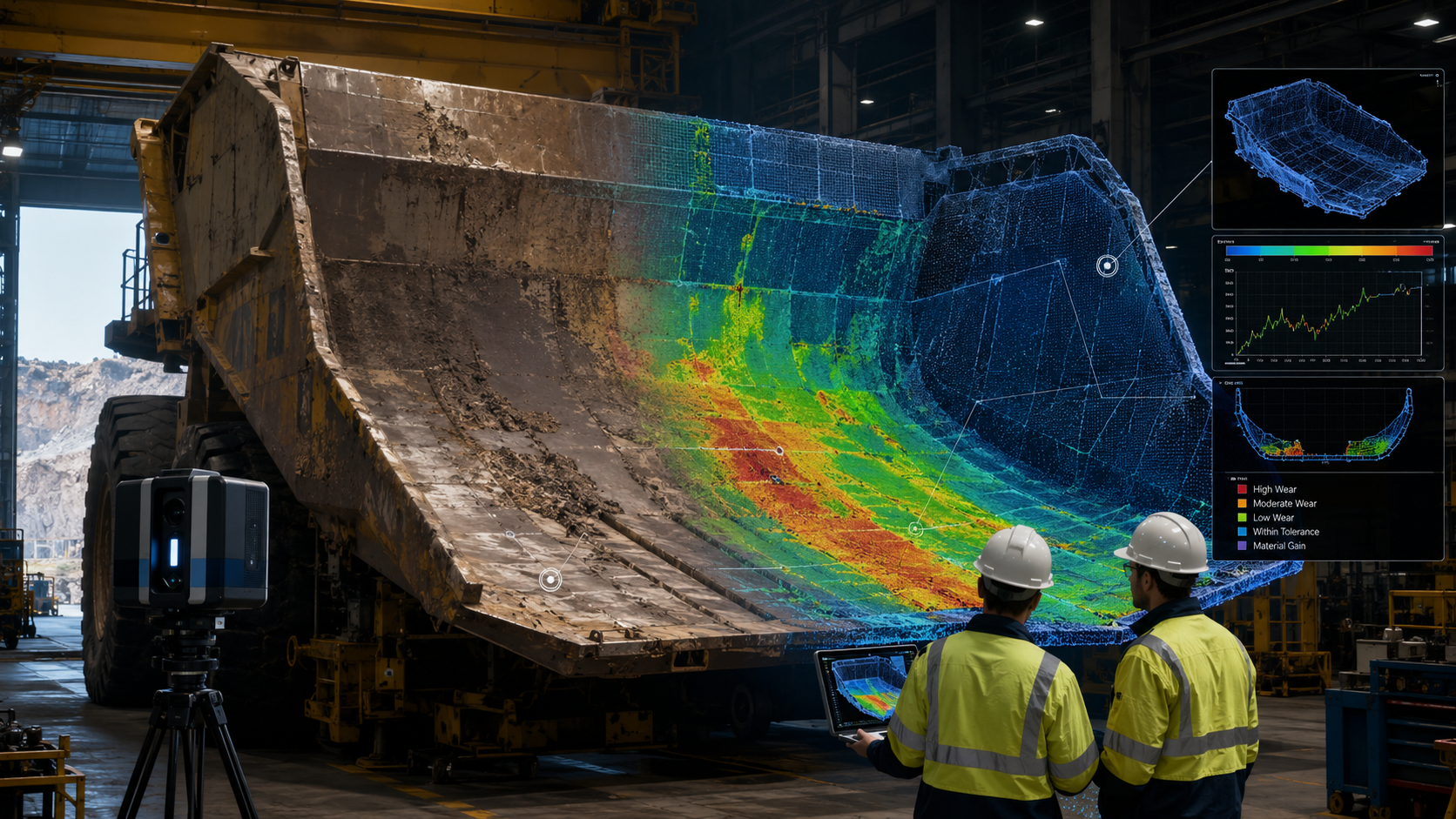
Repeat 3D laser scanning can provide measurable evidence to support this decision. By comparing the geometry of a haul-truck body over time, engineers and maintenance teams can assess how quickly wear and deformation are progressing and identify when intervention may be required.
What Is Haul-Truck Refurbishment Scanning?
Haul-truck refurbishment scanning is the use of high-density 3D laser scanning to capture the current geometry of a truck body, tray, tub or dump body.
The scan creates a detailed three-dimensional point cloud representing the internal and external surfaces of the structure. This data can then be used to assess:
- Wear across the floor, sidewalls, canopy and tail section
- Localised deformation or distortion
- Changes in body geometry
- Damaged or displaced mounting points
- Liner condition and remaining material
- Areas requiring repair or reinforcement
- Changes between inspection periods
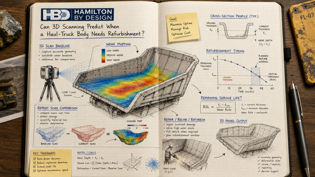
A single scan provides an accurate record of the body at a particular point in time. Repeat scans provide considerably more value because they show how the structure is changing.
Why Visual Inspections May Not Be Enough
Visual inspections remain an important part of haul-truck maintenance. However, they may not provide enough information to quantify the extent or rate of deterioration.
Several maintenance questions can be difficult to answer using visual inspection and manual measurements alone:
- How much has the floor worn since the previous shutdown?
- Is deformation increasing or remaining stable?
- Which areas are wearing faster than expected?
- Is the body suitable for another operating campaign?
- Should the tray be repaired on site or sent for major refurbishment?
- Is the liner protecting the parent structure effectively?
- Can refurbishment be delayed without creating unacceptable risk?
Manual measurements may also be difficult to reproduce consistently across a large, irregular structure.
3D scanning creates a more complete geometric record and allows the same areas to be assessed during future inspections.
How Repeat 3D Scanning Supports Refurbishment Decisions
The greatest benefit of 3D scanning is achieved when the haul-truck body is scanned at planned intervals.
For example, a body may be scanned:
- When first placed into service
- Following a major refurbishment
- During planned shutdowns
- At predetermined operating-hour intervals
- After abnormal loading or impact events
- Before relining or structural repair
- When deformation or cracking is suspected
Each scan can be registered to a common reference system and compared with the previous dataset.
This creates a measurable history of wear and deformation.
The comparison may show:
- Material loss between scanning campaigns
- Increasing floor or sidewall deformation
- Changes to the canopy or rear body geometry
- Localised wear around impact zones
- Movement of structural mounting points
- Areas where liners are no longer providing adequate protection
- Sections of the body deteriorating faster than the surrounding structure
This information supports more evidence-based maintenance planning.
Can 3D Scanning Determine Remaining Service Life?
3D scanning does not independently determine the exact remaining service life of a haul-truck body.
Remaining service life depends on several factors, including:
- Material properties
- Plate and liner thickness
- Loading conditions
- Payload characteristics
- Haul-road conditions
- Operating cycles
- Impact severity
- Existing cracking
- Previous repairs
- Structural fatigue
- Maintenance history
However, repeat scanning can provide important geometric evidence for a broader remaining-service-life assessment.
When scanning data is combined with thickness measurements, crack inspections, operating history, material information and engineering analysis, it can help maintenance teams estimate whether deterioration is stable, gradual or accelerating.
The scan data may also support decisions about whether the body should:
- Continue operating
- Receive local repairs
- Be relined
- Be reinforced
- Undergo partial refurbishment
- Be removed for major structural refurbishment
- Be replaced
Measuring Wear Progression Over Time

A single scan identifies the current condition of the body. A sequence of scans helps establish the rate of change.
For example, if repeated scanning shows that a high-impact section of the floor is losing material at a consistent rate, the maintenance team may be able to estimate when the area is likely to reach a nominated repair threshold.
Similarly, if deformation increases significantly between two inspection periods, this may indicate:
- A change in operating conditions
- Overloading
- Liner failure
- Structural weakening
- Cracking or weld deterioration
- Damage to the body mounting arrangement
The rate of change may be more important than the individual measurement.
A body with visible deformation that remains stable may require a different maintenance response from a body showing rapid geometric change.
Comparing the Scan With Design Geometry
Where original CAD models, fabrication drawings or previous survey records are available, the current point cloud can be compared with the intended design geometry.
This may help identify:
- Floor sagging
- Bowing of sidewalls
- Canopy distortion
- Tail or rear structure deformation
- Misaligned mounting points
- Localised plate displacement
- Structural twisting
- Variation from the original body profile
The comparison can be presented as a colour deviation map, cross-section, dimensional report or engineering drawing.
This provides a clear visual representation of where the body geometry differs from the nominated reference.
Where original design information is unavailable, an earlier scan or a known serviceable body may be used as the comparison reference.
Supporting Repair and Relining Planning
3D scanning can also support the preparation of refurbishment and repair scopes.
The point cloud may be used to:
- Identify the boundaries of worn areas
- Measure damaged regions
- Develop replacement plate geometry
- Model liner sections
- Confirm clearances and interfaces
- Measure structural members and stiffeners
- Locate mounting features
- Produce repair drawings
- Support fabrication planning
- Estimate the extent of replacement material
This can reduce uncertainty before the truck body is removed from service.
Maintenance and fabrication teams can better understand the expected scope, prepare materials and plan labour before refurbishment begins.
Establishing a Refurbishment Baseline
After a body has been refurbished, a new 3D scan can establish an updated baseline.
This baseline records the condition and geometry of the body at the start of its next operating period.
Future scans can then be compared against the post-refurbishment geometry to assess:
- How quickly the new liners are wearing
- Whether repaired areas remain stable
- Whether deformation has returned
- Whether structural changes are occurring in the same locations
- Whether the refurbishment has improved service performance
This provides valuable feedback for future body design, liner selection and maintenance strategies.
Applications Across Different Haul-Truck Body Types
The same scanning approach may be applied to different types of haul-truck bodies, including:
- Standard dump bodies
- Mine-specific tray designs
- Lightweight bodies
- Coal bodies
- Hard-rock mining bodies
- High-abrasion bodies
- Quarry truck bodies
- Custom transport bodies
- Water carts and converted truck bodies
The inspection strategy should be developed around the body design, material handled, operating environment and the maintenance decision being considered.
Typical 3D Scanning Deliverables
Depending on the project requirements, haul-truck body scanning deliverables may include:
- Registered 3D point cloud
- E57, RCP, RCS or LAS scan files
- Colour deviation maps
- Cross-sections through critical areas
- Wear and deformation comparison reports
- Dimensional inspection tables
- Existing-condition drawings
- 3D CAD models
- Repair or refurbishment models
- Fabrication drawings
- Change-over-time comparisons
- Annotated images for maintenance review
The deliverables should be selected according to how the information will be used.
A maintenance planner may require a concise wear report, while an engineering or fabrication team may require detailed CAD geometry and repair drawings.
Benefits for Mining Maintenance Teams
A planned haul-truck refurbishment scanning program may help maintenance teams:
- Improve the timing of refurbishment work
- Reduce reliance on subjective visual assessments
- Identify rapid wear before major damage develops
- Compare wear performance across the truck fleet
- Improve shutdown planning
- Prepare repair materials in advance
- Reduce unexpected refurbishment scope
- Support maintenance budgeting
- Retain traceable condition records
- Improve communication between operations, maintenance, engineering and fabricators
The objective is not to replace engineering judgement. It is to provide better evidence for that judgement.
Important Limitations
3D scanning primarily records visible surface geometry.
It does not replace:
- Ultrasonic thickness testing
- Magnetic-particle inspection
- Dye-penetrant inspection
- Weld inspection
- Material testing
- Fatigue assessment
- Structural engineering analysis
- OEM inspection requirements
Internal cracking, hidden corrosion and subsurface defects may not be visible in the scan data.
For this reason, 3D scanning is most effective when used as part of a broader inspection and asset-management program.
A Practical Scanning Strategy
A practical haul-truck body monitoring program may include:
- Establishing a baseline scan after manufacture or refurbishment.
- Identifying critical wear and deformation zones.
- Recording operating hours, payload conditions and material type.
- Repeating scans at planned maintenance intervals.
- Comparing each scan with the baseline and previous inspection.
- Measuring the rate of geometric change.
- Combining scan results with thickness and crack inspection data.
- Defining repair, relining and refurbishment thresholds.
- Updating the baseline after major work is completed.
The inspection interval may then be adjusted as more condition data becomes available.
Engineering-Led 3D Scanning for Haul-Truck Refurbishment
Hamilton By Design provides engineering-led 3D laser scanning, dimensional verification, reverse engineering and CAD support for mining equipment and fixed plant.
For haul-truck bodies, our services may include:
- Existing-condition scanning
- Wear and deformation assessment
- Repeat-scan comparison
- Refurbishment planning
- Repair modelling
- Liner and plate measurement
- Mounting-point verification
- Existing-condition drawings
- Scan-to-CAD modelling
- Fabrication and repair documentation
Our focus is on producing practical engineering information that can support maintenance, repair and refurbishment decisions.
Plan Haul-Truck Refurbishment With Better Condition Data
Determining when a haul-truck body should be refurbished requires more than identifying visible wear.
Repeat 3D scanning provides a measurable record of how the body is changing. When combined with inspection history, thickness testing, operating data and engineering assessment, it can support more informed decisions about repair, relining and major refurbishment.
To discuss 3D scanning of a haul-truck body, tray or dump body, contact Hamilton By Design.

Contact Us – Talk To Us
Our clients:
























