Robotics and Human Relations: Balancing Innovation with Safety

Robots are no longer the stuff of science fictionโ€”they are embedded in our factories, warehouses, and even food-processing plants. They promise efficiency, speed, and the ability to take on dangerous jobs humans shouldnโ€™t have to do. Yet, as recent headlines show, this promise comes with serious risks. From the lawsuit against Tesla over a robotic arm that allegedly injured a worker to the tragic death of a Wisconsin pizza factory employee crushed by a machine, the conversation about humanโ€“robot relations has never been more urgent.

This blog post explores the promise and peril of robotics in the workplace, drawing lessons from recent incidents and asking: how do we ensure humans and robots can coexist safely?

The Rise of Robotics in Everyday Work

Robotics is spreading quickly across industries. Automotive giants like Tesla rely on robotic arms for precision assembly, while food plants use automated systems to handle packaging and processing. According to the International Federation of Robotics, robot installations worldwide continue to grow year after year. For businesses, itโ€™s a clear win: fewer errors, lower costs, and reduced human exposure to dangerous tasks.

But with robots entering smaller facilitiesโ€”where safety infrastructure may be weakerโ€”the risks grow. A mis calibrated robot, a missed safety step, or a poorly trained operator can turn a productivity tool into a deadly hazard.

When Robots Go Wrong: Lessons from Recent Cases

  • Teslaโ€™s Robotic Arm Lawsuit
    A former technician at Tesla claims he was struck and knocked unconscious by a robotic arm while performing maintenance. The lawsuit highlights a crucial point: safety procedures like lockout/tagout arenโ€™t optionalโ€”they are lifesaving. When machines are energized during servicing, even a momentary slip can have devastating consequences.
  • Wisconsin Pizza Factory Fatality
    In a smaller manufacturing plant, a worker lost his life after being crushed by a robotic machine. Unlike Tesla, this wasnโ€™t a high-tech car factory but a food facilityโ€”showing that robotics risks extend far beyond Silicon Valley. Smaller plants may lack robust safety training, yet they are increasingly embracing automation.

Both cases are tragic reminders that technology alone canโ€™t guarantee safety. Human oversight, training, and organizational commitment to safety matter just as much.

The Human Side of Robotics

When people think about robots at work, they often picture job displacement. But for many workers, the immediate concern is safety. Studies show that trust plays a huge role: workers who believe robots are reliable tend to perform better. However, misplaced trustโ€”assuming a machine will always stop when neededโ€”can be just as dangerous as fear or mistrust.

Beyond physical risks, robots can also affect morale and mental health. Workers may feel devalued or expendable when machines take over critical tasks. The challenge isnโ€™t just engineering safer robotsโ€”itโ€™s creating workplaces where humans feel respected and protected.

Illustrated infographic titled โ€œThe Human Side of Robotics,โ€ showing workers interacting with industrial robots and highlighting concerns such as collaboration, trust, stress, training needs, ethics, safety, and human dignity. Several people appear worried or stressed, with speech bubbles saying โ€œCan I trust this robot?โ€ and โ€œWe need more training.โ€ Warning symbols, safety locks, scales representing ethics, and a newspaper headline reading โ€œInjuryโ€ emphasize workplace risks. A robotic arm works within a safety cage while workers discuss safety and ethical implications. The overall theme contrasts human concerns with the increasing use of robotics.

Building a Safer Future Together

So how do we strike the right balance between robotics innovation and human well-being? A few key steps stand out:

  1. Design Safety Into the Machine: Emergency stops, advanced sensors, and fail-safes should be standard featuresโ€”not optional add-ons.
  2. Enforce Safety Protocols: OSHAโ€™s lockout/tagout rules exist for a reason. Employers must ensure that servicing robots without proper shutdowns is never allowed.
  3. Invest in Training: Robots are only as safe as the people who interact with them. Ongoing, practical training helps prevent accidents.
  4. Foster a Safety Culture: Workers should feel empowered to report unsafe practices without fear of retaliation.
  5. Update Regulations: As robots spread into more industries, regulators must adapt. International safety standards like ISO 10218 need to be more widely enforced, especially in smaller facilities.
Hamilton By Design logo displayed on a blue tilted rectangle with a grey gradient background

Conclusion

Robotics is here to stay. It has the potential to make our workplaces more efficient, less physically demanding, and even safer. But incidents like those at Tesla and the Wisconsin pizza plant remind us that without proper safeguards, the cost of automation can be measured in human lives.

The future of humanโ€“robot relations doesnโ€™t have to be one of fear or tragedy. With the right mix of engineering, regulation, and workplace culture, robots and humans can work side by sideโ€”not as rivals, but as partners. The question isnโ€™t whether we should embrace robotics, but whether weโ€™ll do so responsibly, putting peopleโ€™s safety and dignity first.


Name
Would you like us to arrange a phone consultation for you?
Address

3D LiDAR scanning and 3D modelling service button โ€” laser scanner capturing a point cloud for engineering and CAD modelling
Mechanical engineering services
Finite Element Analysis (FEA) engineering simulation button
Mechanical engineering services
3D LiDAR Scanning Darwin for engineering surveys, laser scanning, reality capture and point cloud modelling services
3D LiDAR Scanning Australia engineering services for laser scanning, reality capture, scan-to-CAD, Scan-to-BIM and as-built documentation across Australia
3D LiDAR scanning services on the Central Coast providing engineering-grade laser scanning, point cloud capture, scan-to-CAD modelling and industrial reality capture for infrastructure and industrial projects.
3D LiDAR Scanning Perth for engineering surveys, laser scanning, reality capture and point cloud modelling services
3D LiDAR Scanning Sydney for engineering surveys, laser scanning, reality capture and point cloud modelling services
3D LiDAR Scanning Brisbane for engineering surveys, laser scanning, reality capture and point cloud modelling services
3D LiDAR Scanning Canberra for engineering surveys, laser scanning, reality capture and point cloud modelling services
3D LiDAR Scanning Newcastle for engineering surveys, laser scanning, reality capture and point cloud modelling services
3D LiDAR Scanning Adelaide for engineering surveys, laser scanning, reality capture and point cloud modelling services

Seeing the Unseen: How LiDAR Scanning is Transforming Mining Process Plants

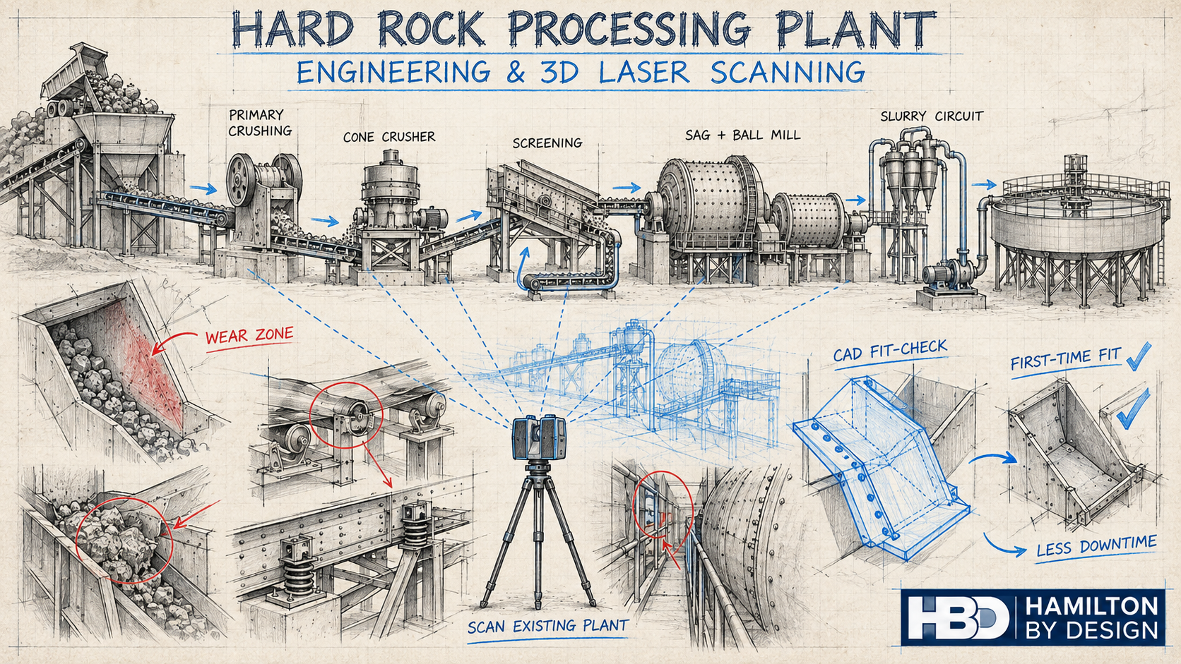
In modern mining, where uptime is money and safety is non-negotiable, understanding the geometry of your process plant is critical. Every conveyor, chute, pipe rack, and piece of equipment must fit together seamlessly and operate reliably โ€” but plants are messy, dusty, and constantly changing. Manual measurement with a tape or total station is slow, risky, and often incomplete.

nfographic showing how LiDAR scanning is used in mining process plants, with illustrations of conveyors, crushers, tanks, mills and chutes. Labels highlight applications such as stockpile volumetrics, crusher inspections, safety and risk management, chute wear and blockages, mill wear measurement, tank deformation monitoring and creating digital twins.

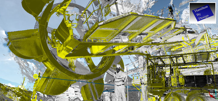
This is where LiDAR scanning (Light Detection and Ranging) has become a game-changer. By capturing millions of precise 3D points per second, LiDAR gives engineers, maintenance planners, and operators an exact digital replica of the plant โ€” without climbing scaffolds or shutting down equipment. In this post, weโ€™ll explore how mining companies are using LiDAR scanning to solve real problems in processing plants, improve safety, and unlock operational efficiency.


What Is LiDAR Scanning?

LiDAR is a remote sensing technology that measures distance by firing pulses of laser light and recording the time it takes for them to return. Modern terrestrial and mobile LiDAR scanners can:

  • Capture hundreds of thousands to millions of points per second
  • Reach tens to hundreds of meters, depending on the instrument
  • Achieve millimeter-to-centimeter accuracy
  • Work in GPS-denied environments, such as inside mills, tunnels, or enclosed plants (using SLAM โ€” Simultaneous Localization and Mapping)

The output is a point cloud โ€” a dense 3D dataset representing surfaces, equipment, and structures with stunning accuracy. This point cloud can be used as-is for measurements or converted into CAD models and digital twins.


Why Process Plants Are Perfect for LiDAR

Unlike greenfield mine sites, processing plants are some of the most geometry-rich and access-constrained areas on site. They contain:

  • Complex networks of pipes, conveyors, tanks, and structural steel
  • Moving equipment such as crushers, mills, and feeders
  • Dusty, noisy, and hazardous environments with limited safe access

All these factors make traditional surveying difficult โ€” and sometimes dangerous. LiDAR enables โ€œno-touchโ€ measurement from safe vantage points, even during operation. Multiple scans can be stitched together to create a complete model without shutting down the plant.


Applications of LiDAR in Process Plants

1. Wear Measurement and Maintenance Planning

LiDAR has revolutionized how mines measure and predict wear on critical process equipment:

  • SAG and Ball Mill Liners โ€“ Portable laser scanners can capture the exact wear profile of liners. Comparing scans over time reveals wear rates, helping maintenance teams schedule relines with confidence and avoid premature failures.
  • Crusher Chambers โ€“ Scanning inside primary and secondary crushers is now faster and safer than manual inspections. The resulting 3D model allows engineers to assess liner life and optimize chamber profiles.
  • Chutes and Hoppers โ€“ Internal scans show where material buildup occurs, enabling targeted cleaning and redesign to prevent blockages.

Result: Reduced downtime, safer inspections, and better forecasting of maintenance budgets.


2. Retrofit and Expansion Projects

When modifying a plant โ€” installing a new pump, rerouting a pipe, or adding an entire circuit โ€” having an accurate โ€œas-builtโ€ model is crucial.

  • As-Built Capture โ€“ LiDAR provides an exact snapshot of the existing plant layout, eliminating guesswork.
  • Clash Detection โ€“ Designers can overlay new equipment models onto the point cloud to detect interferences before anything is fabricated.
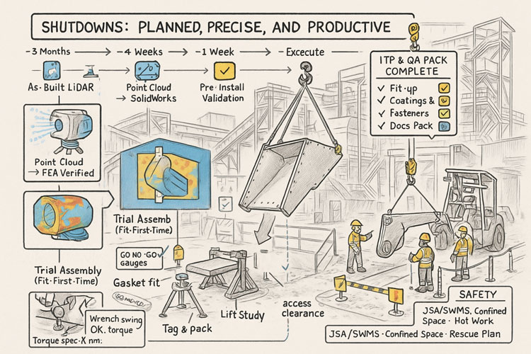
  • Shutdown Optimization โ€“ With accurate geometry, crews know exactly what to cut, weld, and install โ€” reducing surprise field modifications and shortening shutdown durations.

3. Inventory and Material Flow Monitoring

LiDAR is not just for geometry โ€” itโ€™s also a powerful tool for tracking material:

  • Stockpile Volumetrics โ€“ Mounted scanners on stackers or at fixed points can monitor ore, concentrate, and product stockpiles in real time.
  • Conveyor Load Measurement โ€“ Stationary LiDAR above belts calculates volumetric flow, giving a direct measure of throughput without contact.
  • Blending Control โ€“ Accurate inventory data improves blending plans, ensuring consistent plant feed quality.

4. Safety and Risk Management

Perhaps the most valuable application of LiDAR is keeping people out of harmโ€™s way:

  • Hazardous Floor Areas โ€“ When flooring or gratings fail, robots or drones with LiDAR payloads can enter the area and collect data remotely.
  • Fall-of-Ground Risk โ€“ High walls, bin drawpoints, and ore passes can be scanned for unstable rock or buildup.
  • Escape Route Validation โ€“ Scans verify clearances for egress ladders, walkways, and platforms.

Every scan effectively becomes a permanent digital record โ€” a baseline for monitoring ongoing structural integrity.


5. Digital Twins and Advanced Analytics

A plant-wide LiDAR scan is the foundation of a digital twin โ€” a living, data-rich 3D model connected to operational data:

  • Combine scans with SCADA, IoT, and maintenance systems
  • Visualize live process variables in context (flow rates, temperatures, vibrations)
  • Run โ€œwhat-ifโ€ simulations for debottlenecking or energy optimization

As AI and simulation tools mature, the combination of geometric fidelity and operational data opens new possibilities for predictive maintenance and autonomous plant operations.


Emerging Opportunities

Looking forward, there are several promising areas for LiDAR in mining process plants:

  • Autonomous Scan Missions โ€“ Using quadruped robots (like Spot) or SLAM-enabled drones to perform routine scanning in high-risk zones.
  • Real-Time Change Detection โ€“ Continuous scanning of critical assets with alerts when deformation exceeds thresholds.
  • AI-Driven Point Cloud Analysis โ€“ Automatic object recognition (valves, flanges, motors) to speed up model creation and condition reporting.
  • Integrated Planning Dashboards โ€“ Combining LiDAR scans, work orders, and shutdown schedules in a single interactive 3D environment.

Best Practices for Implementing LiDAR

To maximize the value of LiDAR scanning, consider:

  1. Define the Objective โ€“ Are you measuring wear, planning a retrofit, or building a digital twin? This affects scanner choice and resolution.
  2. Plan Scan Positions โ€“ Minimize occlusions and shadow zones by preplanning vantage points.
  3. Use Proper Registration โ€“ Tie scans to a control network for consistent alignment between surveys.
  4. Mind the Environment โ€“ Dust, fog, and vibration can degrade data; choose scanners with appropriate filters or protective housings.
  5. Invest in Processing Tools โ€“ The raw point cloud is only the start โ€” software for meshing, modeling, and analysis is where value is extracted.
  6. Train Your Team โ€“ Build internal capability for scanning, processing, and interpreting the results to avoid vendor bottlenecks.

Infographic showing a 3D LiDAR scanner on a tripod surrounded by eight best-practice principles: start with clear objectives, plan your scanning campaign, prioritize safety, optimize data quality, ensure robust registration and georeferencing, establish repeatability, integrate with downstream systems, and train people with documented procedures

LiDAR scanning is no longer a niche technology โ€” it is rapidly becoming a standard tool for mining process plants that want to operate safely, efficiently, and with fewer surprises. From mill liners to stockpiles, from shutdown planning to digital twins, LiDAR provides a clear, measurable view of assets that was impossible a decade ago.

For operations teams under pressure to deliver more with less, the case is compelling: better data leads to better decisions. And in a high-stakes environment like mineral processing, better decisions translate directly to improved uptime, reduced costs, and safer workplaces.

The next time youโ€™re planning a shutdown, a retrofit, or even just trying to understand why a chute is plugging, consider pointing a LiDAR scanner at the problem. You may be surprised at how much more you can see โ€” and how much time and money you can save.

3D Scanning | Mining Surface Ops | 3D Modelling

Mechanical Engineering | Structural Engineering

Mechanical Drafting | Structural Drafting

3D CAD Modelling | 3D Scanning

Chute Design

SolidWorks Contractors in Australia

Hamilton By Design โ€“ Blog

Finite Element Analysis (FEA) engineering simulation button
Mechanical engineering services

Lessons from a Landmark Case:

The Importance of Robust Structural Design Review

In 2024, SafeWork SA concluded a landmark case involving a spectator-roof collapse during a football club redevelopment project in South Australia. While no life-threatening injuries occurred, the incident highlighted how critical it is for design, review, and certification processes to work together to ensure safety on site.

This was the first successful design-related prosecution under South Australiaโ€™s Work Health and Safety Act, sending a clear signal to the engineering and construction sector: design decisions carry legal and safety obligations, not just technical ones.

Infographic titled โ€œLessons from a Landmark Case,โ€ showing engineers reviewing a design, icons highlighting robust review procedures, proper certification, time-pressure risks, and legal design responsibilities. The lower illustration depicts a structure collapsing after four column failures with two workers falling, emphasising the message โ€œSafety starts at the drawing board

What Happened (Briefly)

During roof sheeting works in late 2021, four of seven supporting columns of a cantilevered spectator roof failed, causing two apprentices to slide down the roof sheets. SafeWork SAโ€™s investigation found that the anchor bolts specified for the column base plates were inadequate and did not meet the requirements of the National Construction Code (NCC).

An independent compliance review also failed to detect this issue, allowing the error to pass unchecked into construction. The result was a collapse that could have had far more severe consequences had the roof been fully loaded or occupied.

Key Learnings for the Industry

This case underscores several important lessons for engineers, designers, project managers, and certifiers:

1. Design Responsibility Is a WHS Duty

Under the WHS Act, designers have a duty to ensure their work is safe not just in its intended use, but during construction. This means bolts, connections, and base plates must be designed for real-world loads โ€” including wind uplift, combined shear and tension, and concrete breakout limits per NCC and relevant Australian Standards.

2. Review Procedures Must Be Robust โ€” and Followed

Having a documented review procedure is not enough if it isnโ€™t rigorously applied. Independent verification and internal peer review are critical to catching design errors before they reach site.

3. Certification Is Not a Rubber Stamp

Independent certifiers play a key role in safeguarding public safety. They must actively verify that designs meet compliance, rather than simply sign off on documentation.

4. Time Pressures Can Compromise Safety

Compressed project timelines were noted as a factor in missed opportunities to catch the error. Project teams must resist the temptation to shortcut review steps when schedules are tight โ€” safety must remain non-negotiable.

5. Documentation & Traceability Protect Everyone

Maintaining calculation records, checklists, and review signoffs creates a clear audit trail. This helps demonstrate due diligence if something goes wrong.

Infographic titled โ€˜Lessons From a Landmark Caseโ€™ displayed on a clipboard. It highlights key learnings from a structural failure case: design compliance, safety standards, bolts failure, and adequate specifications. At the centre is a simple line drawing of a collapsed structure, with arrows pointing to four labelled boxes describing the importance of regulatory compliance, workplace safety standards, anchor bolt failures, and using suitable components to meet project requirements

Why This Matters

The collapse at Angaston Football Club was a relatively small incident with minor injuries โ€” but it could easily have been catastrophic. By learning from cases like this, the industry can improve its processes and prevent future failures.

As professionals, our role is to design for safety, verify rigorously, and document clearly. Doing so protects workers, end-users, and our own organisations.

Legal & Ethical Considerations

This post is intended as a learning resource, not as an allocation of blame. The case referenced is a matter of public record through SafeWork SA and SAET decisions, and all commentary here focuses on general principles of safe design and compliance.

We recommend that other practitioners review their own QA and certification procedures in light of this case to ensure compliance with the National Construction Code and WHS obligations.

More Information —> The Advertiser / Adelaide Now

Hamilton By Design logo displayed on a blue tilted rectangle with a grey gradient background

Mechanical Engineering | Structural Engineering

Mechanical Drafting | Structural Drafting

3D CAD Modelling | 3D Scanning

Chute Design

SolidWorks Contractors in Australia

Hamilton By Design โ€“ Blog

Finite Element Analysis (FEA) engineering simulation button
Mechanical engineering services

The Future of Smelting & Steelmaking:

Trends Shaping a Greener, Smarter Industry


Steel has been the backbone of industrial progress for over 150 years. It is the invisible framework behind our skyscrapers, bridges, transport systems, and modern cities. But the industry that gave us the Industrial Revolution is now facing one of the greatest transitions in its history. The combined pressures of climate change, regulatory scrutiny, fluctuating energy costs, and global trade realignments are forcing steelmakers to rethink how steel is made, used, and traded.

Recent news reports show a fascinating picture: a sector in the middle of transformation, experimenting with new technologies like hydrogen-based direct reduction, while still relying on traditional blast furnace smelting to meet soaring demand. In this article, we explore the future direction of the smelting and steelmaking industry, what challenges lie ahead, and where the biggest opportunities are likely to emerge.


The Push for Green Steel

Hydrogen & Direct Reduced Iron (DRI): A Pathway to Decarbonization

Hydrogen-based steel production remains the single most promising pathway for deep decarbonization in the steel sector. Instead of using metallurgical coal and coke to chemically reduce iron ore, hydrogen can be used to produce direct reduced iron (DRI) that can then be melted in an electric arc furnace (EAF). This dramatically cuts COโ‚‚ emissions, especially if the hydrogen is produced using renewable energy.

Projects like Salzgitterโ€™s Salcos program in Germany are leading the way. Salzgitter has been developing one of the most ambitious hydrogen-based steel transformation roadmaps in Europe, gradually phasing in hydrogen reduction units and retiring carbon-intensive blast furnaces. Similarly, Australiaโ€™s NeoSmelt initiative, backed by Rio Tinto and ARENA, is exploring a combination of DRI and electric smelting furnaces to create a pathway that works for Australian ore quality and energy markets.

But this transition is anything but smooth. Salzgitter has recently delayed later stages of its program, citing economic and regulatory headwinds, such as the high cost of hydrogen, uncertain carbon pricing, and the slow rollout of renewable energy infrastructure. This highlights a hard truth: the green transition will not be instant or cheap. The next decade will likely be defined by pilot projects, incremental scale-ups, and careful balancing between economic viability and climate commitments.


The Coal Paradox

Even as green steel makes headlines, metallurgical coal is seeing a surprising resurgence. Demand for coal-based blast furnace production remains robust, especially in China and India, where domestic infrastructure spending continues to grow. In fact, recent research from the Global Energy Monitor shows that coal-based capacity is still expanding, even as global climate targets call for steep reductions in emissions.

This paradox points to the transitional nature of the current era. For the foreseeable future, the world will be living in a dual-track steel economy: one track relying on traditional blast furnaces and coke ovens to meet near-term demand, and another experimenting with hydrogen, electric smelting, and alternative reduction technologies.

For businesses, this means they cannot simply abandon existing capacity overnight. Instead, expect to see retrofit investments to improve the efficiency of blast furnaces, capture more waste heat, and install carbon capture and storage (CCS) where feasible. This โ€œcleaner coalโ€ approach will act as a bridge until low-carbon technologies can compete at scale on cost and availability.


Regional Shifts & Strategic Investments

Australiaโ€™s Green Steel Ambitions

Australia is emerging as a key player in the global conversation on sustainable steelmaking. The country has vast high-grade iron ore resources, growing renewable energy capacity, and a strategic interest in maintaining domestic steelmaking capability.

  • BlueScopeโ€™s $1.15B blast furnace reline at Port Kembla is one of the largest industrial projects in the nationโ€™s history, designed to keep steel production secure for another 20 years. This investment shows that Australia is taking a pragmatic approach โ€” continuing to support blast furnace technology while planning for a green future.
  • The NeoSmelt project, which just secured nearly $20M in government funding, is a potential game-changer. It will explore how to combine renewable-powered hydrogen and electric furnaces to make a commercial-scale green steel process that works with Australian ore.
  • The potential takeover of Whyalla Steelworks by a consortium led by BlueScope could turn the plant into a testbed for low-emissions ironmaking, providing a national blueprint for decarbonizing heavy industry.

Global Trade & Policy Realignment

Meanwhile, trade policy is also shaping the future. The EU and U.S. have resumed talks to revisit steel and aluminium tariffs, with a focus on creating carbon-based trade measures. If implemented, this could reward producers who adopt low-carbon technologies while penalizing those that rely on high-emission processes. For global producers, this will accelerate investment in low-emissions capacity to stay competitive in export markets.


Innovation Beyond Furnaces

The transformation of steelmaking is not just about switching fuels โ€” itโ€™s about reimagining the entire production system.

  • Modular, low-emission smelting plants like those being developed in Western Australia by Metal Logic allow companies to build capacity closer to demand centers, reduce transport emissions, and scale production up or down as needed.
  • Digital twins and AI-driven process control are making smelting more efficient. By modeling every step of the steelmaking process, producers can optimize energy use, reduce material losses, and increase yield โ€” all of which improve profitability and lower emissions simultaneously.
  • Circular economy practices, such as increased use of scrap steel in EAFs, are becoming a central strategy. Recycling steel uses a fraction of the energy required to make virgin steel and fits neatly into the industryโ€™s sustainability narrative.

This convergence of physical and digital innovation will likely create a new generation of steel plants that are smaller, smarter, and cleaner than their 20th-century predecessors.


Where the Industry is Headed

Looking ahead, the future of smelting and steelmaking will be defined by hybridization, regulation, and resilience:

  • Hybrid production systems will dominate for at least the next decade. Expect blast furnaces to operate alongside hydrogen-based DRI units and electric smelters as companies transition gradually.
  • Stricter carbon regulations will push companies to adopt low-carbon pathways faster than market forces alone would dictate. Carbon border adjustment mechanisms (CBAMs) will effectively tax โ€œdirty steelโ€ in major economies, making investment in green capacity a competitive necessity.
  • Domestic capability building will remain critical. The COVID-era supply chain crises reminded governments why domestic production matters. Expect to see policies that support keeping steelmaking onshore, even if that requires subsidies or preferential procurement.
  • Collaborative innovation will become the norm. Mining giants, energy producers, and technology firms are already forming alliances to solve the โ€œgreen steel puzzle.โ€ This cross-industry collaboration will unlock new efficiencies and accelerate commercialization.

Final Thoughts

The smelting and steelmaking industry is standing at the crossroads of history. The coming years will test its ability to balance sustainability with profitability, scale with flexibility, and tradition with innovation.

Companies that embrace this challenge โ€” investing in low-carbon technology, digital transformation, and strategic partnerships โ€” will not just survive the coming disruption but thrive as leaders in a new, greener industrial age. Steel may be one of the oldest materials in human civilization, but its future is being forged right now, and it has never been more exciting.

References

Salzgitter Salcos Project

Global Energy Monitor โ€“ Steel Sector Reports

ARENA NeoSmelt Funding Announcement

Challenges in the Australian Smelting Industry

3D LiDAR scanning and 3D modelling service button โ€” laser scanner capturing a point cloud for engineering and CAD modelling
Mechanical engineering services
Finite Element Analysis (FEA) engineering simulation button
Mechanical engineering services

Chute Design in the Mining Industry

Infographic showing Hamilton By Designโ€™s engineering workflow, including millimetre-accurate LiDAR reality capture, material-flow simulation, optimised chute designs, and safer, more efficient production outcomes. Two workers in PPE highlight reliable design and longer liner life, with icons representing time, cost and quality benefits.

Getting Coal, Hard Rock, and ROM Material Flow Right

Chute design is one of the most critical yet challenging aspects of mining and mineral processing. Whether you are handling coal, hard rock ore, or raw ROM material, chutes and transfer stations are the unsung workhorses of every operation. When designed well, they guide material smoothly, minimise wear, and keep conveyors running. When designed poorly, they cause blockages, spillage, excessive dust, and expensive downtime.

Modern chute design has moved far beyond rules of thumb and back-of-the-envelope sketches. Today, successful projects rely on accurate as-built data, particle trajectory analysis, and advanced Discrete Element Method (DEM) simulation to predict, visualise, and optimise material flow before steel is cut. In this article, we explore why these tools have become essential, how they work together, and where software can โ€” and cannot โ€” replace engineering judgement.


Illustration showing common problems with poorly designed material-handling chutes. A chute discharges material onto a conveyor while issues are highlighted around it: unpredictable material flow, material spillage, maintenance challenges, high wear, blockages, and dust and noise. Warning icons for downtime and cost appear on the conveyor, and workers are shown dealing with the resulting hazards and maintenance tasks.

The Challenge of Chute Design

Coal and hard rock have very different flow behaviours. Coal tends to be softer, generate more dust, and be prone to degradation, while hard rock is more abrasive and can damage chutes if impact angles are not controlled. ROM material adds another level of complexity โ€” oversize lumps, fines, and moisture variation can cause hang-ups or uneven flow.

Chute design must balance several competing objectives:

  • Control the trajectory of incoming material to reduce impact and wear
  • Prevent blockages by maintaining flowability, even with wet or sticky ore
  • Manage dust and noise to meet environmental and workplace health requirements
  • Fit within existing plant space with minimal modification to conveyors and structures
  • Be maintainable โ€” liners must be accessible and replaceable without excessive downtime

Meeting all these goals without accurate data and simulation is like trying to design in the dark.


Illustrated graphic showing a tripod-mounted 3D laser scanner capturing millimetre-accurate as-built data in an industrial plant with conveyors and walkways. Speech bubbles highlight issues such as โ€œOutdated drawings donโ€™t tell the full storyโ€ and โ€œModifications rarely get documented.โ€ The scan data is shown being visualised on a laptop, with notes describing full coverage of conveyors, walkways, and services. Benefits listed along the bottom include faster data collection, fewer site revisits, safer shutdowns, accurate starting point for design simulation, and safer outcomes that ensure designs fit first time.

Capturing the Truth with 3D Scanning

The first step in any successful chute project is to understand the as-built environment. In many operations, drawings are outdated, modifications have been made over the years, and the real plant geometry may differ from what is on paper. Manual measurement is slow, risky, and often incomplete.

This is where 3D laser scanning changes the game. Using tripod-mounted or mobile LiDAR scanners, engineers can capture the entire transfer station, conveyors, surrounding steelwork, and services in a matter of hours. The result is a dense point cloud with millimetre accuracy that reflects the true state of the plant.

From here, the point cloud is cleaned and converted into a 3D model. This ensures the new chute design will not clash with existing structures, and that all clearances are known. It also allows maintenance teams to plan safe access for liner change-outs and other work, as the scanned model can be navigated virtually to check reach and access envelopes.


Understanding Particle Trajectory

Once the physical environment is known, the next challenge is to understand the particle trajectory โ€” the path that material takes as it leaves the head pulley or previous transfer point.

Trajectory depends on belt speed, material characteristics, and discharge angle. For coal, fine particles may spread wider than the coarse fraction, while for ROM ore, large lumps may follow a ballistic path that needs to be controlled to prevent impact damage.

Accurately modelling trajectory ensures that the material enters the chute in the right location and direction. This minimises impact forces, reducing wear on liners and avoiding the โ€œsplashโ€ that creates spillage and dust. It also prevents the material from hitting obstructions or dead zones that could lead to build-up and blockages.

Modern software can plot the trajectory curve for different loading conditions, providing a starting point for chute geometry. This is a critical step โ€” if the trajectory is wrong, the chute design will be fighting against the natural path of the material.


The Power of DEM Simulation

While trajectory gives a first approximation, real-world flow is far more complex. This is where Discrete Element Method (DEM) simulation comes into play. DEM models represent bulk material as thousands (or millions) of individual particles, each following the laws of motion and interacting with one another.

When a DEM simulation is run on a chute design:

  • You can visualise material flow in 3D, watching how particles accelerate, collide, and settle
  • Impact zones become clear, showing where liners will wear fastest
  • Areas of turbulence, dust generation, or segregation are identified
  • Build-up points and potential blockages are predicted

This allows engineers to experiment with chute geometry before fabrication. Angles can be changed, ledges removed, and flow-aiding features like hood and spoon profiles or rock-boxes optimised to achieve smooth, controlled flow.

For coal, DEM can help ensure material lands gently on the receiving belt, reducing degradation and dust. For hard rock, it can ensure that the energy of impact is directed onto replaceable wear liners rather than structural plate. For ROM ore, it can help prevent oversize lumps from wedging in critical locations.


Illustration of an optimised chute design showing material flow represented by green particles, with check marks and gear icons indicating improved efficiency and engineered performance.

๐Ÿ–ฅ Strengths and Limitations of Software

Modern DEM packages are powerful, but they are not magic. Software such as EDEM, Rocky DEM, or Altairโ€™s tools can simulate a wide range of materials and geometries, but they rely on good input data and skilled interpretation.

Key strengths include:

  • Ability to model complex, 3D geometries and particle interactions
  • High visualisation power for communicating designs to stakeholders
  • Capability to run multiple scenarios (different feed rates, moisture contents, ore types) quickly

However, there are limitations:

  • Material calibration is critical. If the particle shape, friction, and cohesion parameters are wrong, the results will not match reality.
  • Computational cost can be high โ€” detailed simulations of large chutes with millions of particles may take hours or days to run.
  • Engineering judgement is still needed. Software will not tell you the โ€œbestโ€ design โ€” it will only show how a proposed design behaves under given conditions.

Thatโ€™s why DEM is best used as part of a holistic workflow that includes field data, trajectory analysis, and experienced design review.


From Model to Real-World Results

When the simulation results are validated and optimised, the design can be finalised. The point cloud model ensures the chute will fit in the available space, and the DEM results give confidence that it will perform as intended.

This means fabrication can proceed with fewer changes and less risk. During shutdown, installation goes smoothly, because clashes have already been resolved in the digital model. Once commissioned, the chute delivers predictable flow, less spillage, and longer liner life.


Why It Matters More Than Ever

Todayโ€™s mining operations face tighter production schedules, stricter environmental compliance, and increasing cost pressures. Downtime is expensive, and the margin for error is shrinking.

By combining 3D scanning, trajectory modelling, and DEM simulation, operations can move from reactive problem-solving to proactive improvement. Instead of waiting for blockages or failures, they can design out the problems before they occur, saving both time and money.


Partnering for Success

At Hamilton by Design, we specialise in turning raw site data into actionable insights. Our team uses advanced 3D scanning to capture your transfer stations with precision, builds accurate point clouds and CAD models, and runs calibrated DEM simulations to ensure your new chute design performs from day one.

Whether youโ€™re working with coal, hard rock, or ROM ore, we help you deliver designs that fit first time, reduce maintenance headaches, and keep production running.

Contact us today to see how our integrated scanning and simulation workflow can make your next chute project safer, faster, and more reliable.

Mechanical Engineering | Structural Engineering

Mechanical Drafting | Structural Drafting

3D Laser Scanning | 3D CAD Modelling | 3D Scanning

Chute Design

SolidWorks Contractors in Australia

Hamilton By Design โ€“ Blog

Consulting Engineers

About Us โ€“ Hamilton By Design

Hamilton By Design | 3D Scanning | Sydney | Perth | Brisbane | Mount Isa | Lidar Scanning

Contact us

3D CAD Modelling Australia service banner for Hamilton By Design
3D LiDAR scanning and 3D modelling service button โ€” laser scanner capturing a point cloud for engineering and CAD modelling
Mechanical engineering services
3D CAD Modelling Australia service banner for Hamilton By Design
Mechanical, Structural & Pipework Drafting service banner by Hamilton By Design featuring white text on a blue background.
Australian Drafting logo featuring bold white text reading "Australian Drafting" centred on a blue rounded rectangle background.
Blue banner graphic displaying the text "Point Cloud to CAD - Australia" in large white lettering, representing point cloud processing, scan-to-CAD conversion and digital engineering services across Australia.
CHPP Engineering title graphic featuring bold white text reading "CHPP Engineering" centred on a blue rounded rectangle background.
Engineering Governance title graphic featuring bold white text reading "Engineering Governance" centred on a blue rounded rectangle background.
Mechanical engineering services
Australian Drafting logo featuring bold white text reading "Australian Drafting" centred on a blue rounded rectangle background.
3D LiDAR Scanning Hunter & Newcastle banner with white text on a blue background promoting engineering-grade laser scanning services for industrial, mining and infrastructure projects across the Hunter Valley and Newcastle region.
Mechanical Engineering Hunter & Newcastle banner promoting mechanical engineering services for mining, industrial plants, power generation, manufacturing and heavy industry throughout the Hunter Valley and Newcastle region.
Structural Drafting Hunter & Newcastle banner promoting structural drafting services for mining, industrial plants, power generation, manufacturing and infrastructure projects across the Hunter Valley and Newcastle region.
Mechanical Engineering Perth WA banner for Hamilton By Design featuring white text on a blue background.
3D Laser Scanning Perth WA banner for Hamilton By Design with white text on a blue background.
SolidWorks Perth WA banner for Hamilton By Design featuring white text on a blue background.
Fabrication and product design services
Finite Element Analysis (FEA) engineering simulation button
3D LiDAR scanning and 3D modelling service button โ€” laser scanner capturing a point cloud for engineering and CAD modelling
Blue rounded button with the text โ€œSolidWorks Designโ€ in white.
Mechanical drafting services button
Structural drafting services button

3D Scanning Sydney banner promoting engineering-grade 3D laser scanning, LiDAR scanning, and reality capture services by Hamilton By Design.
Mechanical Engineering Sydney banner with white text on a blue background representing Hamilton By Design's mechanical engineering services in Sydney.
Mechanical Drafting and 3D Modelling Sydney banner highlighting Hamilton By Design's CAD drafting, 3D modelling, and engineering design services in Sydney.

Mechanical Engineering | Structural Engineering


Chute Design at Hamilton By Design

Chute Design at Hamilton By Design

At Hamilton by Design, we see ourselves as more than engineers โ€” we are problem-solvers who bring both science and experience to the table. Every bulk material transfer is unique, and each one carries its own challenges. By combining the principles of particle physics with decades of hands-on site experience, we design chutes and transfer points that perform in the real world, not just on a computer screen.

We are a small, specialised company, not a large corporate machine. That means you deal directly with the people who understand your operation, your materials, and your challenges. We take pride in our ability to stand on-site, watch the flow of material, and recognise behaviours that only years of experience can teach. This gives us the clarity to engineer practical solutions that keep your plant running reliably.

For us, your success is our success. We measure our achievement not by the number of projects we complete, but by the value we add to your operation โ€” less dust, less wear, fewer stoppages, more tonnes moved.

Learn more about our approach and solutions Hamilton By Design – Chute Design


Our clients:

Name
Would you like us to arrange a phone consultation for you?
Address

Mechanical
Engineering
| Structural
Engineering

3D LiDAR scanning and 3D modelling service button โ€” laser scanner capturing a point cloud for engineering and CAD modelling
Mechanical engineering services

Mechanical
Drafting
| Structural
Drafting

3D
Laser Scanning
| 3D
CAD Modelling
| 3D
Scanning

SolidWorks
Contractors in Australia

Hamilton By Design โ€“ Blog

Consulting Engineers

About Us โ€“
Hamilton By Design