As-Built Drawings from a LiDAR Scanner

As-Built Drawings from a LiDAR Scanner

Turning reality capture into reliable documentation for the building industry

Blue 3D LiDAR scanner icon on a tripod with scanning waves

In modern construction, as-built drawings are no longer a โ€œnice to haveโ€ at the end of a project. Theyโ€™re critical for compliance, future upgrades, maintenance and dispute resolution. The problem is that traditional as-built drawings often rely on red-pen markups, partial measurements and rushed updates done after practical completion.

LiDAR scanning changes this completely. By capturing millions of accurate points in a matter of minutes, a LiDAR scanner allows engineers and drafters to create as-built drawings that reflect the real, built condition โ€“ not what was on the original design.
Hamilton By Design uses 3D LiDAR scanning to generate accurate as-built drawings from a LiDAR scanner, giving builders, architects, engineers and asset owners a defensible digital record of their building or plant.


What are as-built drawings from a LiDAR scanner?

As-built drawings from a LiDAR scanner are:

  • 2D plans, sections and elevations
  • 3D models and details
  • derived directly from a registered point cloud captured on site.

Instead of manually measuring walls, slab setouts, penetrations and services, a LiDAR scanner records the whole space. The point cloud is then brought into CAD (e.g. SolidWorks, Revit or other platforms), where key elements are modelled and documented.

Typical outputs include:
  • Architectural as-builts (floor plans, elevations, reflected ceiling plans)
  • Structural as-builts (columns, beams, slabs, penetrations, bracing)
  • Services as-builts (pipework, ductwork, cable trays, equipment locations)
  • Detailed shop drawings for plant rooms and complex interfaces

How the workflow works

  1. LiDAR scanning on site
    • Rapid capture of internal and external spaces
    • Minimal disruption to trades and building users
    • Safe access to congested or hard-to-reach areas
  2. Point cloud registration and cleaning
    • Multiple scans stitched together into a single, accurate model
    • Aligned to site control or building grid where available
  3. 3D modelling and drafting
    • Critical building elements are modelled from the point cloud
    • As-built geometry is used to produce 2D drawings and 3D models
  4. Issue of as-built drawing pack
    • PDF drawings for records and certifications
    • DWG / RVT / STEP or other formats for future projects
    • Optional viewer files so non-CAD users can navigate the 3D data

Pros of as-built drawings from a LiDAR scanner

1. High accuracy and completeness

  • Millions of measurement points capture true geometry, not assumptions.
  • Complex areas โ€“ plant rooms, risers, ceiling spaces โ€“ are fully documented, not just partially measured.

2. Reduced rework and disputes

  • Clear evidence of what was built supports defect resolution and variation claims.
  • Future contractors design to real as-built conditions, reducing clashes and site modifications.

3. Faster capture on busy sites

  • Scanning is quick compared to manual measurement.
  • Ideal for constrained programmes and after-hours access windows.

4. Better coordination between disciplines

  • Structural, architectural and services teams can all reference the same point cloud and models.
  • Less โ€œfinger-pointingโ€ when drawings donโ€™t match whatโ€™s on site.

5. Stronger compliance and asset management

  • As-built drawings support building approvals, fire safety certification and ongoing maintenance planning.
  • Facility managers gain a digital baseline for future upgrades.

Cons and limitations to consider

1. Not every point needs to become a line

LiDAR creates very detailed data. If over-modelled, projects can waste time modelling elements that donโ€™t impact decisions. The key is to define what actually needs to be modelled for compliance, maintenance and future work.

2. Line-of-sight constraints

Scanners work online-of-sight. Hidden voids, behind-ceiling spaces or crowded areas may still need additional access or targeted scans.

3. File sizes and hardware requirements

Point clouds can be large and require good hardware and workflows. We manage this for you, but project teams need suitable software or viewer tools if they want to work directly with the cloud.

4. Upfront cost vs basic markups

LiDAR-based as-builts cost more than simple red-pen drawings. However, they usually save money by reducing rework, clarifying liability and avoiding surprises on the next project phase.


What LiDAR technology offers the building industry beyond as-builts

LiDAR scanning doesnโ€™t just create better as-built drawings. It unlocks a broader digital toolkit for the building and construction industry.

1. BIM and clash detection

  • Point clouds can be used to validate BIM models, ensuring they match reality.
  • New designs can be checked against the as-built point cloud to spot clashes before anything is fabricated.

2. Digital QA and dimensional control

  • Verify column locations, slab levels, penetrations and set-outs against design tolerances.
  • Check fabricated elements (stairs, walkways, modules) against the point cloud before shipping to site.

3. Refurbishment and fit-out planning

  • Ideal for refurbishing existing buildings, heritage structures and occupied spaces.
  • Designers can test options in 3D, knowing the geometry reflects the real building.

4. Facilities management and digital twins

  • As-built models become the foundation for digital twin environments.
  • Facility managers can track assets, plan maintenance and visualise future upgrades in context.

5. Heritage documentation and risk management

  • Non-intrusive capture of historic facades and interiors.
  • Provides a permanent digital record if damage, fire or future alterations occur.

6. Off-site fabrication and modular construction

  • Accurate as-built geometry allows stair cores, plant skids and faรงade elements to be prefabricated with confidence.
  • Better fit-up on site, fewer hot-work modifications and reduced time at height.

Hamilton By Design logo displayed on a blue tilted rectangle with a grey gradient background
3D LiDAR scanning and 3D modelling service button โ€” laser scanner capturing a point cloud for engineering and CAD modelling
Mechanical engineering services

Why work with Hamilton By Design

Hamilton By Design combines LiDAR scanning, 3D modelling and engineering into one integrated service:

  • We understand both building and industrial environments.
  • We work with architects, builders, engineers and asset owners.
  • We tailor the level of as-built detail to what your project actually needs.

Whether youโ€™re closing out a project with reliable as-built drawings, planning a major refurbishment, or laying the groundwork for digital twins, as-built drawings from a LiDAR scanner provide a precise, future-proof record of your building.

Our clients:

Name
Address
You would like to:

3D Laser Scanning

Transforming Projects with 3D Scanning in Sydney

3D LiDAR Scanning โ€“ Digital Quality Assurance

3D LiDAR Laser Scanning & Drafting Services in Chatswood & Greater Sydney – Hamilton By Design

Reality Capture Brisbane title graphic with white text on a blue background promoting reality capture, LiDAR scanning and digital engineering services in Brisbane, Queensland.
3D Scanning Brisbane text graphic on a blue background promoting engineering-led laser scanning and reality capture services in Brisbane.

LiDAR Scanning Brisbane title graphic with white text on a blue background promoting terrestrial LiDAR scanning, point cloud capture and reality capture services in Brisbane, Queensland.
SolidWorks Brisbane title graphic with white text on a blue background promoting SolidWorks mechanical design, 3D CAD modelling and engineering drafting services in Brisbane, Queensland.


3D Scanning Sydney banner promoting engineering-grade 3D laser scanning, LiDAR scanning, and reality capture services by Hamilton By Design.
Mechanical Engineering Sydney banner with white text on a blue background representing Hamilton By Design's mechanical engineering services in Sydney.
Mechanical Drafting and 3D Modelling Sydney banner highlighting Hamilton By Design's CAD drafting, 3D modelling, and engineering design services in Sydney.

Mechanical Engineering | Structural Engineering


Next-Generation 3D Modelling & Scanning Advances in 2025

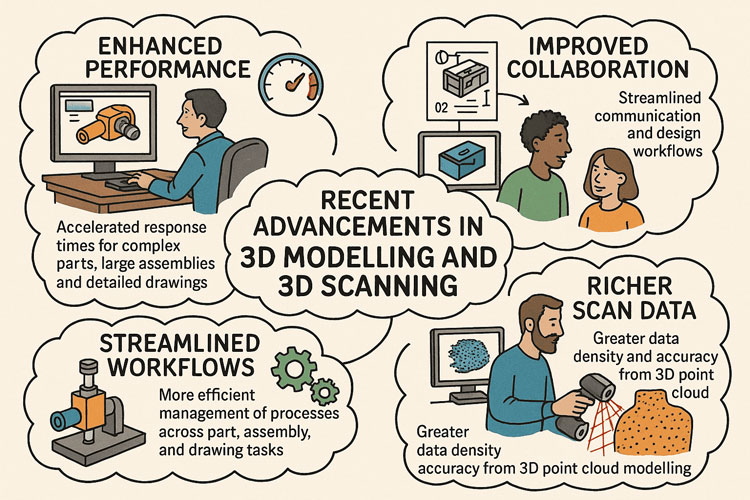
Illustrated infographic titled โ€œRecent Advancements in 3D Modelling and 3D Scanning.โ€ It features four themed sections around a central title. โ€œEnhanced Performanceโ€ shows a person working on a computer with faster response times for complex parts and assemblies. โ€œImproved Collaborationโ€ depicts two people discussing streamlined design communication. โ€œStreamlined Workflowsโ€ shows a microscope and gears representing improved management of part, assembly, and drawing processes. โ€œRicher Scan Dataโ€ shows a technician scanning an object and a computer displaying a dense point cloud model, emphasising greater accuracy and data density. The overall image highlights modern improvements in modelling, collaboration, workflows, and point cloud scanning.

1. Collaboration and Data Management

Collaboration is increasingly centred around 3D data. Modern platforms now let teams review, comment on, and markup native 3D models directly inside the design environment. Instead of relying solely on screenshots or static drawings, stakeholders can spin, section, and measure live models for better context. Real-time update notifications and cloud-connected revision control ensure that scanned 3D data and parametric CAD models stay synchronized โ€” critical when working with reality capture data that represents the as-built environment. Hybrid data management options combine local PDM systems with cloud platforms, supporting distributed teams handling massive point clouds or mesh data. This tight integration means that model changes โ€” whether from new design iterations or updated scans โ€” propagate instantly across the project team. Decision-making becomes more visual and informed, keeping everyone aligned around a single, authoritative 3D dataset. Collaboration is no longer a separate process but embedded into daily 3D workflows.


2. Smarter Part Modelling

3D modelling tools are now more intelligent and better suited for working with scan-derived geometry. Designers can quickly apply chamfers, fillets, and shells across complex surfaces, even those imported from meshes or point cloud extractions. Automated bend notch creation and sheet metal tools are optimized to work with geometry derived from scanning existing parts, making reverse-engineering and fabrication preparation much faster. Reference geometry patterning allows engineers to build parametric frameworks over point cloud regions, speeding up master model creation. Cleanup utilities now support selectively removing unnecessary features or smoothing noisy scan data without rebuilding the entire model history. These advances turn what used to be a labour-intensive process into a streamlined workflow that transforms raw reality capture data into production-ready models. The focus is on reducing friction between physical and digital โ€” allowing engineers to move quickly from scan to design, then to manufacturing.


3. Large Assembly Performance

Point cloud and mesh datasets are often extremely large, so performance improvements are critical. Modern CAD platforms now handle assemblies containing both traditional parametric models and massive scan data without bringing systems to a crawl. Engineers can duplicate components while maintaining mates, overlay scans onto assemblies to check fit, and perform interference detection even in lightweight modes. Visualization performance has been tuned for high-density point clouds, allowing smooth pan, zoom, and rotate interactions even with billions of points. Simplification and decimation tools let users strip out unneeded scan detail for faster load times while retaining critical geometry. Seamless transitions between lightweight review and full edit mode make it possible to work interactively with scanned environments. This capability is especially valuable for plant layout, construction validation, and retrofitting projects, where the ability to handle large, mixed-format 3D datasets directly within assemblies is a competitive advantage.


4. Enhanced Drawings and Documentation

Although 3D is the primary medium, 2D documentation remains essential โ€” especially for suppliers and manufacturing partners. Modern CAD environments generate drawings directly from parametric models or scan-based reconstructions, ensuring that documentation matches the latest as-built conditions. Multi-approval stamps, BOM quantity overrides, and standards compliance tools make it easy to document parts created from reverse engineering or field measurement data. Automatic view generation and model-based definition (MBD) help reduce the reliance on fully manual drawings, embedding dimensions and tolerances directly into the 3D model where possible. For projects using scans, section views can be cut through the point cloud or mesh to produce accurate reference drawings without redrawing geometry. These improvements ensure that documentation is both faster to produce and more accurate โ€” giving fabrication teams confidence that the deliverables reflect real-world conditions rather than idealized design intent.


5. Seamless ECAD/MCAD Integration

The convergence of 3D scanning and electronics integration is enabling more precise mechatronic design. Point cloud models of housings, enclosures, and factory floors can be combined with PCB outlines and component data for fit validation. Modern tools allow importing copper traces, vias, and keep-out regions into the mechanical model to run thermal or clearance checks directly against scanned geometry. This prevents collisions and ensures proper heat management early in the design cycle. Real-time synchronization between ECAD and MCAD domains means that if a scanned housing reveals unexpected tolerances, electrical designers can adjust their board layout accordingly. The result is a more accurate digital twin that accounts for both the designed and as-built states. This tighter integration avoids costly late-stage changes, shortens time-to-market, and ensures that mechanical and electrical systems are developed with a shared, reliable 3D reference that reflects physical reality.


6. Performance and Visualization

Visualization is where 3D scanning truly shines. GPU-accelerated engines now render massive point clouds, meshes, and parametric geometry in real time, allowing teams to virtually โ€œwalk throughโ€ captured environments or inspect reverse-engineered parts at full fidelity. Silhouette-based defeature tools can strip away irrelevant details while maintaining enough geometry for accurate reviews and clash detection. Cached mass property calculations extend to mesh and hybrid models, giving accurate weight and center of gravity data even from scan-derived parts. Photorealistic rendering using real-time ray tracing allows stakeholders to experience designs exactly as they will look, bridging the gap between scanned reality and proposed modifications. This level of visual fidelity improves collaboration, reduces the need for physical mock-ups, and accelerates stakeholder buy-in. High-quality 3D visualization is no longer a luxury โ€” it is a daily tool for engineers, designers, and decision-makers alike.


7. Future Outlook

The future of 3D modelling is increasingly driven by AI and reality capture. Expect CAD platforms to automatically recognize features within point clouds โ€” holes, slots, threads โ€” and generate parametric features with minimal user input. Cloud-native workflows will make it easier to process extremely large scan datasets without local performance bottlenecks. Automated drawing generation and model-based definition will continue to reduce documentation overhead, while digital twin technology will tie live sensor data to scanned geometry for ongoing validation. Generative design powered by AI will be able to work directly with scanned environments, proposing optimized solutions that account for real-world constraints. This convergence of scanning, modelling, and simulation promises a future where physical and digital coexist seamlessly โ€” enabling engineers to capture, design, simulate, and validate with unprecedented speed and accuracy, ultimately transforming how products, factories, and infrastructure are created and maintained.

Hamilton By Design logo displayed on a blue tilted rectangle with a grey gradient background

3D Modelling | 3D Scanning | Point Cloud Scanning

Our clients:

Name
Would you like us to arrange a phone consultation for you?
Address

3D Laser Scanning of Hotels

3D Scanning for Construction in Sydney

3d laser scanning for engineering

Finite Element Analysis (FEA) engineering simulation button
Mechanical engineering services

3D Scanning Sydney banner promoting engineering-grade 3D laser scanning, LiDAR scanning, and reality capture services by Hamilton By Design.
Mechanical Engineering Sydney banner with white text on a blue background representing Hamilton By Design's mechanical engineering services in Sydney.
Mechanical Drafting and 3D Modelling Sydney banner highlighting Hamilton By Design's CAD drafting, 3D modelling, and engineering design services in Sydney.

Mechanical Engineering | Structural Engineering


Harnessing the Power of LiDAR

Harnessing the Power of LiDAR: Revolutionizing Engineering with 3D Scanning & SolidWorks

Title: Harnessing the Power of LiDAR: Revolutionizing Engineering with 3D Scanning & SolidWorks

Introduction

At Hamilton By Design, we are committed to integrating cutting-edge technologies to enhance our engineering processes. One such technology that has transformed the landscape of design and construction is LiDAR (Light Detection and Ranging). This advanced 3D scanning tool offers unparalleled precision and efficiency, enabling us to deliver superior outcomes for our clients.

The Evolution of LiDAR Technology

LiDAR technology has come a long way since its inception in the 1960s. Initially developed for meteorological and atmospheric research, it has evolved into a versatile tool used across various industries, including civil engineering, architecture, and environmental monitoring. The integration of GPS and advancements in laser technology have significantly enhanced LiDAR’s accuracy and applicability.

Advantages of Incorporating LiDAR into Engineering

  1. Exceptional Accuracy and Detail LiDAR systems emit laser pulses to measure distances with remarkable precision, creating high-resolution point clouds that capture intricate details of structures and terrains. This level of accuracy is crucial for tasks such as topographic mapping, structural analysis, and as-built documentation.
  2. Efficiency in Data Collection Traditional surveying methods can be time-consuming and labor-intensive. LiDAR, on the other hand, can rapidly collect vast amounts of data, significantly reduce field time and accelerate project timelines.
  3. Enhanced Safety and Accessibility LiDAR enables remote data collection in hazardous or hard-to-reach areas, minimizing risks to personnel. Whether it’s scanning a deteriorating structure or surveying rugged terrain, LiDAR ensures safety without compromising data quality.
  4. Integration with BIM and Digital Twins The detailed 3D models generated by LiDAR can be seamlessly integrated into Building Information Modeling (BIM) systems, facilitating better design visualization, clash detection, and project coordination. This integration supports the creation of digital twins, allowing for real-time monitoring and maintenance planning.
  5. Cost-Effectiveness By reducing the need for repeated site visits and minimizing errors through accurate data capture, LiDAR contributes to cost savings throughout the project lifecycle. Its efficiency translates into reduced labor costs and optimized resource allocation.

Applications in Engineering Projects

At Hamilton By Design, we’ve leveraged LiDAR technology across various projects:

  • Infrastructure Development: Accurate terrain modeling for road and bridge design.
  • Heritage Conservation: Detailed documentation of historical structures for preservation efforts.
  • Urban Planning: Comprehensive city modeling to inform sustainable development.

Conclusion

The integration of LiDAR 3D scanning tools into our engineering processes has revolutionized the way we approach design and construction. Its precision, efficiency, and versatility align with our commitment to delivering innovative and high-quality solutions.

As technology continues to advance, we remain dedicated to adopting tools like LiDAR that enhance our capabilities and set new standards in engineering excellence.

Laser Scan | Hamilton By Design
3D LiDAR scanning and 3D modelling service button โ€” laser scanner capturing a point cloud for engineering and CAD modelling
Mechanical engineering services

For more information on how Hamilton By Design utilizes LiDAR technology in our projects, visit our website at www.hamiltonbydesign.com.au.

Mechanical Engineers Structural Engineers

Structural Drafting | Mechanical Drafting | 3D Laser Scanning

Mechanical Engineering

Want to know how 3D Scanning can help your next project?
Get in touch today at sales@hamiltonbydesign.com.au

Finite Element Analysis (FEA) engineering simulation button
Mechanical engineering services