EinScan vs LiDAR Terrestrial Laser Scanners โ€“ Choosing the Right Tool for Reality Capture

Comparison illustration showing EinScan structured-light scanner on left and FARO LiDAR terrestrial laser scanner on right.

EinScan vs LiDAR Terrestrial Laser Scanners โ€“ Choosing the Right Tool for Reality Capture


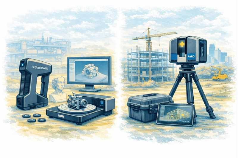
The rapid growth of 3D scanning has given engineers, fabricators and designers access to tools that were once limited to large survey companies. Today you can buy a compact EinScan structured-light scanner for a few thousand dollars or hire a FARO or Leica terrestrial LiDAR scanner capable of mapping an entire processing plant in an afternoon. Both are called โ€œ3D scanners,โ€ yet they serve very different purposes. Understanding the difference between EinScan-style scanners and terrestrial LiDAR systems is essential before investing time or money into reality capture.

Two Technologies, Two Different Jobs

EinScan scanners, produced by SHINING 3D, are primarily structured-light or short-range laser scanners. They project patterns of light onto an object and use cameras to interpret how that light deforms across the surface. The result is a dense mesh model of the objectโ€”typically exported as STL, OBJ or PLY files. EinScan units are designed for objects you can walk around, such as mechanical parts, castings, plastic housings and small assemblies.

Terrestrial LiDAR scanners such as the FARO Focus, Leica RTC360 or Trimble X-series operate on a completely different principle. These instruments sit on a tripod and fire millions of laser pulses across a 360-degree field, measuring the time it takes for each pulse to return. The output is a georeferenced point cloud containing precise XYZ coordinates for everything the laser can seeโ€”buildings, structures, conveyors, tanks, pipework and terrain.

Calling both devices โ€œ3D scannersโ€ is like calling a vernier caliper and a total station the same tool. They both measure, but at entirely different scales.


Visual comparison of EinScan object scanner and LiDAR terrestrial laser scanner in matching sketch style.

Scale and Range

The first and most obvious difference is working range.
An EinScan handheld unit is comfortable scanning parts from a few centimetres up to perhaps three or four metres. It is ideal for a gearbox housing on a bench or the plastic bumper of a vehicle. Once the object grows larger than a small room, the scanner begins to lose tracking and accuracy.

A terrestrial LiDAR scanner is built for the opposite end of the spectrum. A FARO Focus S-series can capture data from 0.6 metres out to 70 metres or more, mapping entire buildings or industrial sites from a single setup. Multiple scans are then registered together to create a complete digital twin of a facility.

For workshops and machine shops the question becomes simple:
Are you scanning an object, or are you scanning a place?
Objects suit EinScan; places suit LiDAR.

Accuracy and Tolerance Expectations

Manufacturers often quote impressive numbers, but real-world accuracy must be considered.

  • EinScan desktop and handheld systems typically achieve 0.05โ€“0.2 mm accuracy on small parts when conditions are ideal.
  • Terrestrial LiDAR scanners deliver around ยฑ1 mm to ยฑ3 mm accuracy over distance.

At first glance EinScan appears โ€œmore accurate,โ€ but this is only true at short range. A LiDAR scanner maintains consistent accuracy across tens of metres, something structured-light devices simply cannot do.

For precision mechanical componentsโ€”bearing fits, machined bores, threaded holesโ€”neither technology replaces traditional metrology tools. Scanning excels at capturing shape and context, while micrometers and CMMs remain the authority for tolerance verification.

Type of Data Produced

EinScan produces mesh files made from millions of tiny triangles. These are excellent for visualisation and 3D printing but contain no intelligence about holes, planes or cylinders. CAD systems like SolidWorks or Fusion 360 cannot directly convert these meshes into editable parametric models without additional reverse-engineering work.

LiDAR scanners generate point cloudsโ€”individual points with coordinates and often colour values. Point clouds are perfect for surveying, clash detection, volume calculations and as-built documentation. They are not intended to be edited like CAD models; instead, engineers build new geometry over the top using the cloud as reference.

Understanding this distinction avoids disappointment. Neither scanner delivers a โ€œone-click CAD model.โ€ Human engineering judgement is always required.

Surface and Environmental Limitations

EinScan technology relies on optical cameras and projected light, which introduces several practical limitations:

  • Shiny or black surfaces are difficult to capture
  • Transparent plastics confuse the cameras
  • Deep holes and narrow slots are often missed
  • Sunlight can overpower the projected pattern
  • Tracking can be lost on large flat surfaces

LiDAR systems are more tolerant of environment. They can operate outdoors, in dusty workshops and over long distances. However, they also struggle with highly reflective materials such as polished stainless steel or glass, and they require careful setup to avoid shadows and occlusions.

Workflow Considerations

A typical EinScan workflow looks like this:

  1. Prepare the partโ€”often with scanning spray
  2. Capture multiple passes
  3. Clean and align the mesh
  4. Export STL/OBJ
  5. Rebuild geometry in CAD using the mesh as reference

This process suits reverse engineering of brackets, castings, vehicle parts and consumer products.

A LiDAR workflow is different:

  1. Set up the scanner at multiple locations
  2. Register scans together in software such as FARO Scene or Leica Cyclone
  3. Classify and clean the point cloud
  4. Use the cloud for measurements, modelling or BIM integration

This approach is ideal for as-built surveys, plant upgrades, brownfield design and digital twins.

Cost and Ownership

EinScan systems range from a few thousand to around twenty thousand dollars. They are accessible to small businesses and even serious hobbyists. Software is generally included, and the learning curve is manageable.

Terrestrial LiDAR scanners are capital equipment. Purchase prices often exceed $60,000โ€“$100,000 before software, training and maintenance. For many companies it makes more sense to engage a specialist scanning provider when required.


Hamilton By Design logo displayed on a blue tilted rectangle with a grey gradient background

Choosing the Right Tool

The decision should be driven by the problem you are solving:

Choose EinScan when you need to:

  • Create a bracket to fit an existing motor
  • Reverse engineer a plastic enclosure
  • Modify a vehicle component
  • Capture complex organic shapes
  • Produce meshes for 3D printing

Choose LiDAR when you need to:

  • Document an industrial facility
  • Design around existing plant and pipework
  • Perform clash detection for upgrades
  • Measure volumes and clearances
  • Create a site-wide digital twin

Many organisations ultimately use both. A LiDAR scan provides the big picture, while an EinScan captures detailed components within that environment.

3D LiDAR scanning and 3D modelling service button โ€” laser scanner capturing a point cloud for engineering and CAD modelling
Mechanical engineering services

Integration with CAD

Engineers often ask which scanner works best with SolidWorks or Fusion 360. The honest answer is that neither integrates directly into parametric CAD without intermediate steps. EinScan meshes require reverse-engineering tools or manual modelling. LiDAR point clouds usually pass through Autodesk Recap, FARO Scene or similar before being referenced in CAD.

Scanning is a method of collecting truth, not generating finished design. The value lies in reducing site visits, avoiding clashes and giving designers confidence about existing conditions.

Final Thoughts

EinScan scanners and terrestrial LiDAR systems are not competitors; they are complementary tools on the reality-capture spectrum. One excels at objects on a bench, the other at assets spread across hectares. Selecting the wrong tool leads to frustration, while choosing correctly can transform the way projects are delivered.

For Australian fabricators and engineers, the key question is simple:
Are you capturing a part, or are you capturing a place?
Answer that, and the choice between EinScan and LiDAR becomes clear.

Name
Would you like us to arrange a phone consultation for you?
Address

3D CAD Modelling Australia service banner for Hamilton By Design
Mining & Processing Perth WA banner for Hamilton By Design featuring white text on a blue background.
Scan to BIM Perth WA banner for Hamilton By Design featuring white text on a blue background.
Ship Building Perth WA banner for Hamilton By Design featuring white text on a blue background.
Structural drafting services button
3D LiDAR scanning and 3D modelling services button
Mechanical drafting services button
3D CAD Modelling Australia service banner for Hamilton By Design
3D LiDAR scanning and 3D modelling service button โ€” laser scanner capturing a point cloud for engineering and CAD modelling
Mechanical engineering services
3D CAD Modelling Australia service banner for Hamilton By Design
Mechanical, Structural & Pipework Drafting service banner by Hamilton By Design featuring white text on a blue background.
Australian Drafting logo featuring bold white text reading "Australian Drafting" centred on a blue rounded rectangle background.
Blue banner graphic displaying the text "Point Cloud to CAD - Australia" in large white lettering, representing point cloud processing, scan-to-CAD conversion and digital engineering services across Australia.
CHPP Engineering title graphic featuring bold white text reading "CHPP Engineering" centred on a blue rounded rectangle background.
Engineering Governance title graphic featuring bold white text reading "Engineering Governance" centred on a blue rounded rectangle background.
Mechanical engineering services
Australian Drafting logo featuring bold white text reading "Australian Drafting" centred on a blue rounded rectangle background.
https://www.hamiltonbydesign.com.au/lidar-scanning-brisbane-2
3D LiDAR Scanning Hunter & Newcastle banner with white text on a blue background promoting engineering-grade laser scanning services for industrial, mining and infrastructure projects across the Hunter Valley and Newcastle region.
Mechanical Engineering Hunter & Newcastle banner promoting mechanical engineering services for mining, industrial plants, power generation, manufacturing and heavy industry throughout the Hunter Valley and Newcastle region.
Structural Drafting Hunter & Newcastle banner promoting structural drafting services for mining, industrial plants, power generation, manufacturing and infrastructure projects across the Hunter Valley and Newcastle region.
Mechanical Engineering Perth WA banner for Hamilton By Design featuring white text on a blue background.
3D Laser Scanning Perth WA banner for Hamilton By Design with white text on a blue background.
SolidWorks Perth WA banner for Hamilton By Design featuring white text on a blue background.
Fabrication and product design services
Finite Element Analysis (FEA) engineering simulation button
3D LiDAR scanning and 3D modelling service button โ€” laser scanner capturing a point cloud for engineering and CAD modelling
Blue rounded button with the text โ€œSolidWorks Designโ€ in white.
Mechanical drafting services button
Structural drafting services button

Mechanical Engineering | Structural Engineering


Why You Should 3D Scan Your White Van Before a Tradie Fit Out?

LiDAR scanning the interior of a white van beside a fully fitted tradie van outside a workshop

Why 3D Scan Your White Van Before a Tradie Fit-Out?

Customising your van is no different to customising your toolbox.

You wouldnโ€™t buy a toolbox full of drawers and shelves that donโ€™t suit your tools โ€” so why accept a van fit-out that doesnโ€™t suit the way you work?

If youโ€™re paying good money for a van fit-out, 3D scanning your van first ensures you actually get what you want, not a generic solution.


3D scanning a white van before a custom tradie fit-out compared to a completed organised van interior

Your Van Is Your Toolbox

For most tradies, the van is:

  • a mobile workshop
  • a storage system
  • an office
  • and a productivity tool

Every trade works differently, and every van gets used differently.

A 3D scan captures the exact internal geometry of your van, so the fit-out is designed around your vehicle, not assumptions.


Why Guessing Costs You Money

Traditional van fit-outs often rely on:

  • standard templates
  • rough measurements
  • generic layouts

That can lead to:

  • wasted space
  • awkward access
  • tools that donโ€™t fit properly
  • shelves and drawers you donโ€™t actually use

Once itโ€™s built, changing it is expensive.

3D scanning removes the guesswork before anything is built.


What 3D Scanning Does for a Van Fit-Out

A 3D scan creates an accurate digital model of your van interior.

This allows the design team to:

  • optimise every millimetre of space
  • design shelving, drawers, racks, and storage to fit properly
  • check clearances before anything is installed
  • tailor the layout to how you work day-to-day

Youโ€™re paying for a fit-out โ€” this ensures you get value from every dollar.


Trades That Benefit from 3D-Scanned Van Fit-Outs

We regularly assist (but are not limited to):

  • Plumbing vans โ€“ pipe storage, fittings, pumps, and access
  • Electrical vans โ€“ cable drums, test equipment, safe storage
  • Carpentersโ€™ vans โ€“ tool cases, saw storage, materials
  • Fittersโ€™ vans โ€“ precision tools, parts, and fast access
  • Boilermakersโ€™ vans โ€“ heavy tools, welding gear, safe load distribution
  • Delivery vans โ€“ optimised load space and restraint systems
  • HVAC / air conditioning vans โ€“ gas bottles, units, tools
  • Painters / decorators โ€“ organised storage for finishes and equipment
  • Locksmiths / security installers โ€“ fast access, clean layout
  • Handymen / general maintenance โ€“ flexibility and adaptability
  • Camper vans โ€“ beds, storage, kitchens, and utilities that actually fit

Different trades. Same problem.
One-size-fits-all doesnโ€™t work.


Design It Right โ€” Before Itโ€™s Built

With a 3D scan, the design team can:

  • trial different layouts digitally
  • adjust storage heights and access
  • confirm everything fits before fabrication

Traditionally, we assist with fit-out design โ€” but scanning takes it further by giving everyone accurate data to work from.

This reduces:

  • rework
  • compromises
  • frustration

Youโ€™re Paying for a Fit-Out โ€” Get What You Want

A van fit-out is an investment.

So ask yourself:

  • Why accept a generic layout?
  • Why compromise on access or storage?
  • Why redesign later when you can get it right first time?

Scan the van. Design it properly. Build it once.


The Bottom Line

Customising your van is just like customising your toolbox.

The better it suits you, the faster you work, the easier your days are, and the more value you get from it.

If youโ€™re already spending money on a fit-out, 3D scanning your van is the smartest way to make sure you get exactly what you want โ€” not what happens to fit.

Name
Would you like us to arrange a phone consultation for you?
Address

3D CAD Modelling Australia service banner for Hamilton By Design
3D LiDAR scanning and 3D modelling service button โ€” laser scanner capturing a point cloud for engineering and CAD modelling
Mechanical engineering services
Finite Element Analysis (FEA) engineering simulation button
Mechanical engineering services

Why Would You 3D Scan Your Vehicle?

Engineer using a LiDAR scanner to capture 3D vehicle geometry while a client reviews point cloud data outside a workshop

Why 3D Scan Your Vehicle? Automotive 3D Scanning Explained

At first glance, 3D scanning a vehicle might sound like something reserved for manufacturers or motorsport teams. In reality, 3D vehicle scanning is becoming increasingly common for everyday automotive projects โ€” from restorations and modifications to verification, documentation, and future-proofing.

So why would someone invest in 3D scanning their vehicle? The answer is simple: accuracy, confidence, and better outcomes.


Turning a Car Into Data

A vehicle 3D scan captures millions of precise measurement points across the surface of a car or its components. This data forms a highly accurate digital model โ€” often called a point cloud โ€” which can then be used for CAD design, analysis, and fabrication.

Unlike manual measurement, 3D scanning:

  • Captures complex curves and surfaces
  • Eliminates guesswork
  • Creates a permanent digital record

Once scanned, your vehicle becomes a measurable digital asset, not just a physical object.


Engineer and client performing automotive 3D scanning of a vehicle outside a workshop using LiDAR technology

1. Reverse Engineering Parts That No Longer Exist

One of the most common reasons people scan vehicles is to recreate parts that canโ€™t be bought anymore.

This is especially relevant for:

  • Classic and vintage cars
  • Imported vehicles
  • Low-production or discontinued models

With a 3D scan, components such as panels, brackets, housings, or trims can be accurately recreated or improved โ€” without relying on worn samples or rough measurements.


2. Custom Modifications That Fit First Time

Custom automotive work only works when parts fit exactly as intended.

People scan their vehicles to design:

  • Body kits, guards, and aero components
  • Custom exhausts and mounts
  • Roll cages and chassis modifications

3D scanning allows designers and fabricators to work from real vehicle geometry, significantly reducing rework, delays, and trial-and-error fitting.


3. Vehicle Restoration and Heritage Preservation

For restoration projects, 3D scanning provides a way to capture the vehicle before changes begin.

Benefits include:

  • Preserving original geometry
  • Recording factory alignment and clearances
  • Digitally archiving rare or historically significant vehicles

This approach is particularly valuable when restoring vehicles where originality and accuracy matter.


4. Accident Damage Assessment and Verification

Not all damage is visible to the naked eye.

After an accident, 3D scanning can:

  • Detect subtle deformation
  • Compare damaged areas against original geometry
  • Provide objective measurement data

This is useful for repair planning, insurance discussions, and verifying whether a vehicle has returned to its intended shape.


5. Motorsport and Performance Development

In motorsport and performance tuning, precision is everything.

Vehicles are scanned to:

  • Analyse body shape and aerodynamics
  • Design lightweight performance components
  • Validate compliance with regulations

3D scanning shortens development cycles and allows performance improvements to be based on measured reality, not assumptions.


6. Quality Control and Build Verification

For custom builds and low-volume manufacturing, scanning provides a way to check what was built against what was designed.

This helps:

  • Verify panel alignment
  • Confirm clearances
  • Identify deviations early

Itโ€™s an objective way to ensure quality and reduce risk before a vehicle is signed off or delivered.


7. Creating a Digital Twin of Your Vehicle

Some owners choose to scan their vehicle simply to create a digital twin โ€” a complete virtual representation of the car.

A digital twin can be used for:

  • Future modifications
  • Ongoing maintenance planning
  • Design work without touching the car

Once created, it becomes a long-term reference that adds value over the vehicleโ€™s lifetime.


8. Improving Collaboration Between Trades

Vehicle projects often involve multiple parties:

  • Owners
  • Engineers
  • Designers
  • Fabricators

A 3D scan ensures everyone works from the same accurate dataset, reducing miscommunication and costly mistakes.


9. Documentation, Insurance, and Peace of Mind

A 3D scan provides:

  • Timestamped evidence of vehicle condition
  • Objective, defensible measurement data
  • Clear documentation for high-value assets

This can be useful for insurance, resale, or engineering certification.


10. Future-Proofing Your Vehicle

Once scanned:

  • The vehicle never needs to be re-measured
  • Data can be reused indefinitely
  • Modifications become easier over time

Many people scan a vehicle once, then benefit from that data for years.


Engineer and client performing vehicle 3D scanning with a car laser scanner in a coastal car park

The Real Reason People Scan Their Vehicles

People donโ€™t scan their vehicles because the technology looks impressive.

They scan them because it:

  • Saves time
  • Reduces risk
  • Improves accuracy
  • Leads to better decisions
3D LiDAR scanning and 3D modelling service button โ€” laser scanner capturing a point cloud for engineering and CAD modelling
Mechanical engineering services

In short:

3D scanning transforms a vehicle from something you measure repeatedly into something you understand completely.


Name
Would you like us to arrange a phone consultation for you?
Address

3D CAD Modelling Australia service banner for Hamilton By Design
3D LiDAR scanning and 3D modelling service button โ€” laser scanner capturing a point cloud for engineering and CAD modelling
Mechanical engineering services
Mechanical drafting services button
Blue rounded button with the text โ€œSolidWorks Designโ€ in white.
Blue banner graphic displaying the text "Point Cloud to CAD - Australia" in large white lettering, representing point cloud processing, scan-to-CAD conversion and digital engineering services across Australia.
Mechanical, Structural & Pipework Drafting service banner by Hamilton By Design featuring white text on a blue background.
Engineering Governance title graphic featuring bold white text reading "Engineering Governance" centred on a blue rounded rectangle background.
Mining Plant Upgrades promotional graphic with bold white text on a blue background representing mining infrastructure, plant improvement, and engineering upgrade projects.
3D Pipework promotional graphic with bold white text on a blue background representing pipework design, modelling, drafting, and engineering services.
Australian Drafting logo featuring bold white text reading "Australian Drafting" centred on a blue rounded rectangle background.
3D Pipework promotional graphic with bold white text on a blue background representing pipework design, modelling, drafting, and engineering services.
Mining Plant Upgrades promotional graphic with bold white text on a blue background representing mining infrastructure, plant improvement, and engineering upgrade projects.
3D LiDAR Scanning for Engineering Projects title graphic featuring bold white text on a blue rounded rectangle background.
Australian Drafting logo featuring bold white text reading "Australian Drafting" centred on a blue rounded rectangle background.
Engineering Governance title graphic featuring bold white text reading "Engineering Governance" centred on a blue rounded rectangle background.
Mechanical, Structural & Pipework Drafting service banner by Hamilton By Design featuring white text on a blue background.
Mechanical engineering services
Blue rounded button with the text โ€œSolidWorks Designโ€ in white.
Finite Element Analysis (FEA) engineering simulation button

Mechanical Engineering | Structural Engineering


Automotive 3D Scanner Technology: From Cars to Complete Vehicle Digitisation

Engineer using an automotive LiDAR scanner to capture 3D vehicle geometry while a client reviews point cloud data

Automotive 3D Scanner Technology | Vehicle & Car Laser Scanning

The automotive industry has always pushed the limits of precision. From body panels and chassis alignment to aftermarket modifications and reverse engineering, accuracy is everything. This is where the automotive 3D scanner has moved from a niche tool to an essential part of modern automotive workflows.

Whether youโ€™re restoring classic vehicles, developing custom components, or validating manufacturing tolerances, 3D scanning of vehicles is now the fastest and most reliable way to capture real-world geometry.


Why Automotive 3D Scanning Matters

Traditional vehicle measurement methods โ€” tape measures, calipers, and manual templates โ€” are slow, subjective, and prone to error. In contrast, vehicle 3D scanning captures millions of data points in minutes, creating a precise digital replica of a car or component.

This digital data can be used for:

  • Reverse engineering parts
  • CAD modelling and redesign
  • Fitment verification
  • Quality control
  • Digital archiving of rare or legacy vehicles

For automotive professionals, accuracy is no longer optional โ€” itโ€™s a competitive advantage.


Engineer and client performing vehicle 3D scanning with a car laser scanner in a coastal car park

What Is a 3D Scanner for Automotive Applications?

A 3D scanner for automotive use is a device that captures the exact shape and dimensions of a vehicle or its components using laser or structured light technology. The result is a highly accurate point cloud or mesh that can be converted into CAD models.

Common scanner types include:

  • Laser-based scanners
  • Structured light scanners
  • Handheld and tripod-mounted systems

For industrial and engineering use, the car laser scanner remains the preferred option due to its accuracy, repeatability, and ability to scan reflective or complex surfaces.


Automotive Use Cases for 3D Scanning

1. 3D Scanning of Vehicle Bodies

Full 3D scanning of vehicle exteriors allows teams to:

  • Capture exact body geometry
  • Design aerodynamic add-ons
  • Validate panel alignment
  • Reproduce damaged or unavailable parts

This is particularly valuable for motorsport, restoration, and custom fabrication projects.


2. 3D Scanner for Cars in Restoration & Classic Vehicles

When original drawings no longer exist, a 3D scanner for cars becomes the only way to accurately reproduce parts.

Applications include:

  • Recreating discontinued components
  • Digitally preserving rare vehicles
  • Designing upgrades without altering originality

3. Automotive Laser Scanning for Manufacturing

In production and fabrication environments, laser scanner automotive systems are used to:

  • Verify tolerances
  • Compare as-built vehicles to CAD
  • Detect deformation or misalignment
  • Reduce rework and scrap

This level of insight is impossible with manual inspection alone.


Choosing the Best 3D Scanner for Automotive Work

Selecting the best 3D scanner for automotive use depends on accuracy requirements, environment, and workflow integration.

Key factors to consider:

  • Accuracy & resolution (sub-millimetre for engineering)
  • Speed of capture
  • Ability to scan reflective surfaces
  • Compatibility with CAD software
  • Portability for workshop or site use

For engineering-grade outcomes, tripod-mounted or hybrid systems often outperform consumer-level handheld devices.


Car Laser Scanner vs Traditional Measurement

A car laser scanner provides several advantages over conventional measurement methods:

Traditional MeasurementAutomotive 3D Scanning
Manual & subjectiveObjective & repeatable
Limited reference pointsMillions of data points
Time-consumingRapid capture
Difficult to archivePermanent digital record

This is why 3D scanning of vehicle geometry is now standard practice in high-value automotive work.


Integrating 3D Scanning Into Automotive Design

Once scanning is complete, the data feeds directly into:

  • CAD design
  • Simulation & analysis
  • Fitment studies
  • Manufacturing workflows

This scan-to-CAD process allows engineers and designers to work from reality, not assumptions.


Automotive 3D Scanning for the Future

As vehicles become more complex โ€” electric drivetrains, lightweight materials, tighter tolerances โ€” vehicle 3D scanning will continue to grow in importance.

Future applications include:

  • Digital twins of vehicles
  • Predictive maintenance modelling
  • AI-driven quality control
  • Automated inspection systems

What was once cutting-edge is now becoming standard practice.


Final Thoughts

An automotive 3D scanner is no longer just a tool for specialists โ€” itโ€™s a foundational technology for modern automotive design, fabrication, and verification.

Whether youโ€™re selecting the best 3D scanner for automotive work, implementing laser scanner automotive systems in production, or using 3D scanning of vehicle geometry for restoration and reverse engineering, the benefits are clear:

  • Higher accuracy
  • Faster workflows
  • Reduced risk
  • Better outcomes

In an industry where millimetres matter, 3D scanning of vehicles delivers confidence โ€” from concept to completion.

3D LiDAR scanning and 3D modelling service button โ€” laser scanner capturing a point cloud for engineering and CAD modelling
Mechanical engineering services
Name
Would you like us to arrange a phone consultation for you?
Address

3D CAD Modelling Australia service banner for Hamilton By Design
3D LiDAR scanning and 3D modelling service button โ€” laser scanner capturing a point cloud for engineering and CAD modelling
Mechanical engineering services
Mechanical drafting services button
Blue rounded button with the text โ€œSolidWorks Designโ€ in white.
Blue banner graphic displaying the text "Point Cloud to CAD - Australia" in large white lettering, representing point cloud processing, scan-to-CAD conversion and digital engineering services across Australia.
Mechanical, Structural & Pipework Drafting service banner by Hamilton By Design featuring white text on a blue background.
Engineering Governance title graphic featuring bold white text reading "Engineering Governance" centred on a blue rounded rectangle background.
Mining Plant Upgrades promotional graphic with bold white text on a blue background representing mining infrastructure, plant improvement, and engineering upgrade projects.
3D Pipework promotional graphic with bold white text on a blue background representing pipework design, modelling, drafting, and engineering services.
Australian Drafting logo featuring bold white text reading "Australian Drafting" centred on a blue rounded rectangle background.
3D Pipework promotional graphic with bold white text on a blue background representing pipework design, modelling, drafting, and engineering services.
Mining Plant Upgrades promotional graphic with bold white text on a blue background representing mining infrastructure, plant improvement, and engineering upgrade projects.
3D LiDAR Scanning for Engineering Projects title graphic featuring bold white text on a blue rounded rectangle background.
Australian Drafting logo featuring bold white text reading "Australian Drafting" centred on a blue rounded rectangle background.
Engineering Governance title graphic featuring bold white text reading "Engineering Governance" centred on a blue rounded rectangle background.
Mechanical, Structural & Pipework Drafting service banner by Hamilton By Design featuring white text on a blue background.
Mechanical engineering services
Blue rounded button with the text โ€œSolidWorks Designโ€ in white.
Finite Element Analysis (FEA) engineering simulation button

Mechanical Engineering | Structural Engineering


Fabrication Integrated Modelling (FIM):

Sydney manufacturing workshop using Fabrication Integrated Modelling to connect engineering design, CNC data, and local steel fabrication.

Fabrication Integrated Modelling (FIM): Why Itโ€™s the Future for Local Fabricators

Why It Is the Future for Local Fabricators

The fabrication industry is undergoing a fundamental transformation. Increasing project complexity, tighter tolerances, compressed schedules, labour shortages, and rising material costs are placing unprecedented pressure on fabricators โ€” particularly local workshops operating in competitive markets. At the same time, clients are demanding greater certainty: certainty of fit, certainty of schedule, and certainty of cost.

Traditional fabrication workflows, built around 2D drawings and manual interpretation, are no longer sufficient to meet these expectations. They rely heavily on experience, assumptions, and rework โ€” all of which introduce risk. In this environment, Fabrication Integrated Modelling (FIM) is emerging not as a luxury, but as a necessity.

FIM represents a shift from drawing-based fabrication to model-driven fabrication, where a single, coordinated digital model governs design intent, fabrication detailing, procurement, machining, assembly, and installation. For local fabricators, this shift offers a path to higher productivity, improved margins, and long-term relevance in an evolving industry.


What Is Fabrication Integrated Modelling (FIM)?

Fabrication Integrated Modelling is a methodology where the fabrication model becomes the primary source of truth across the entire project lifecycle. Instead of treating design, drafting, fabrication, and installation as disconnected stages, FIM integrates them into a continuous digital workflow.

In an FIM environment:

  • Engineering intent is embedded directly into the model
  • Fabrication constraints are considered from the outset
  • Quantities, tolerances, and interfaces are defined digitally
  • Fabrication data flows directly to machines and shop documentation
  • Installation sequencing is validated before material is cut

The model is not merely a visual aid โ€” it is a fully informed digital prototype of the fabricated asset.

From Drawings to Data: A Fundamental Shift

Historically, fabrication has relied on 2D drawings as the primary communication tool. These drawings require interpretation by drafters, trades, and supervisors, each introducing assumptions based on experience and context. While this approach has worked for decades, it becomes increasingly fragile as projects grow more complex.

Fabrication Integrated Modelling replaces interpretation with explicit data. Hole locations, weld preparations, connection details, clearances, and tolerances are all defined within the model. This reduces ambiguity and ensures that everyone โ€” from estimator to machine operator โ€” is working from the same information.

The result is a dramatic reduction in errors, clarifications, and rework.


Why FIM Is Gaining Momentum Now

Several industry pressures are accelerating the adoption of FIM:

  • Increasing complexity of industrial and infrastructure projects
  • Reduced tolerance for errors during shutdowns and brownfield upgrades
  • Labour shortages and loss of experienced trades
  • Higher expectations for schedule and cost certainty
  • Growing integration of CNC and automated fabrication equipment

FIM addresses these challenges by improving coordination, predictability, and efficiency at the source โ€” before fabrication begins.


Fabrication Integrated Modelling in a Sydney workshop showing engineers and fabricators using a shared 3D model to drive CNC fabrication and steel assembly.

Key Benefits of Fabrication Integrated Modelling

Reduced Errors and Rework

Rework is one of the most significant drains on fabrication profitability. Errors discovered on the workshop floor or during installation often result in cascading impacts: delays, additional labour, material waste, and strained relationships with clients.

By resolving interfaces, clashes, and tolerances digitally, FIM enables fabricators to identify and eliminate issues before steel is cut. Assemblies are tested virtually, connections are validated, and fit-up risks are significantly reduced.

This proactive approach shifts problem-solving upstream, where changes are faster, cheaper, and less disruptive.


Improved Fabrication Efficiency and Throughput

Fabrication speed is not achieved by rushing work โ€” it is achieved by removing uncertainty. FIM provides clarity on what needs to be fabricated, in what order, and to what tolerance.

Benefits include:

  • Clear fabrication sequencing
  • Reduced downtime waiting for clarifications
  • Better planning of labour and machine utilisation
  • More predictable workshop flow

Local fabricators using FIM often report smoother operations, fewer interruptions, and a higher percentage of โ€œright-first-timeโ€ components.


Better Use of Skilled Labour

Skilled trades are becoming harder to find and retain. Fabrication Integrated Modelling helps maximise the value of skilled workers by giving them better information, not more guesswork.

Fitters receive assemblies that align as expected. Welders focus on quality rather than correcting geometry. Supervisors make decisions based on accurate model data rather than assumptions. Apprentices gain clarity and confidence by working from model-based instructions.

Rather than replacing experience, FIM captures and amplifies it.


Seamless Integration with CNC and Fabrication Equipment

One of the strongest advantages of FIM is its ability to connect directly with modern fabrication equipment. The same model used for coordination and verification can generate machine-ready data, including:

  • NC files for beam lines and plate processors
  • Cut lists and nesting data
  • Part numbers and assembly marks
  • Machining references

This eliminates duplication of effort and reduces the risk of transcription errors. It also shortens the time between design approval and fabrication start, improving responsiveness to project changes.


Competitive Advantage for Local Fabricators

Local fabricators often compete with offshore suppliers on price alone โ€” a contest that is difficult to win. FIM allows local workshops to compete on value rather than cost.

Key differentiators enabled by FIM include:

  • Faster response to changes
  • Higher confidence in fit-up for complex or brownfield sites
  • Reduced installation risk
  • Stronger collaboration with engineers and constructors

When site conditions change โ€” as they inevitably do โ€” local fabricators using FIM can adapt quickly, update models, and deliver revised components without significant disruption. This agility is a powerful advantage over remote fabrication alternatives.


FIM in Brownfield and Upgrade Projects

Brownfield projects present some of the greatest challenges in fabrication. Existing assets rarely match legacy drawings, and tolerances are often tight. Discovering misalignment during installation can result in costly delays and extended shutdowns.

Fabrication Integrated Modelling, often combined with accurate site capture, allows fabricators to design and fabricate components that align with actual site conditions rather than assumptions.

This approach reduces:

  • On-site modifications
  • Temporary works
  • Installation delays
  • Safety risks associated with forced fit-ups

For local fabricators servicing industrial plants and operational facilities, FIM is rapidly becoming an expected capability.


Financial Benefits: Protecting Margins, Not Just Schedules

While FIM is often associated with speed and accuracy, its most important benefit may be margin protection.

Model-based workflows enable:

  • More accurate pricing through reliable quantities
  • Reduced contingency allowances
  • Predictable labour and machine hours
  • Lower material waste
  • Fewer disputes and variations

By increasing certainty, FIM allows fabricators to price work confidently rather than defensively. Over time, this leads to healthier margins and more sustainable operations.


Earlier Engagement and Better Project Outcomes

Fabricators who adopt FIM often find themselves involved earlier in projects. Engineers and asset owners increasingly recognise the value of fabrication input during design development.

Early collaboration enables:

  • Design for manufacture and assembly
  • Smarter connection strategies
  • Reduced installation complexity
  • Improved safety outcomes

This shifts the fabricatorโ€™s role from reactive supplier to active project partner, strengthening relationships and improving project outcomes for all parties.


Overcoming Barriers to Adoption

Adopting Fabrication Integrated Modelling requires investment โ€” not only in software and systems, but in people and processes. Common challenges include:

  • Training requirements
  • Changes to established workflows
  • Initial productivity adjustments
  • Cultural resistance to new methods

Successful fabricators address these challenges incrementally. They start with pilot projects, focus on repeatable wins, and work closely with engineering and modelling partners to build capability over time.

The risk of maintaining outdated workflows is increasingly greater than the risk of change.


The Future of Fabrication: Integrated Digital Ecosystems

FIM is not the final destination โ€” it is the foundation for a more connected fabrication industry. As digital maturity increases, fabrication models will increasingly link to:

  • Digital twins
  • Quality assurance records
  • Traceability and compliance systems
  • Asset management platforms
  • Automated inspection and verification

In this future, the fabrication model becomes a long-term asset, supporting not only construction but operation and maintenance.


Why Fabrication Integrated Modelling Is the Future for Local Fabricators

Local fabrication is not disappearing โ€” it is evolving. Workshops that continue to rely solely on 2D drawings and manual processes will face increasing pressure from cost, risk, and competition. Those that embrace Fabrication Integrated Modelling will position themselves for long-term success.

By adopting FIM, local fabricators can:

  • Deliver higher quality with greater confidence
  • Reduce rework and wasted effort
  • Protect margins in competitive markets
  • Strengthen relationships with engineers and clients
  • Build resilient, future-ready businesses

Fabrication Integrated Modelling is not about replacing trades or experience. It is about supporting them with better information, clearer intent, and integrated workflows.

For local fabricators willing to invest in capability and collaboration, FIM is not just the future โ€” it is the pathway to remaining relevant, competitive, and profitable in an increasingly digital industry.

3D LiDAR scanning and 3D modelling service button โ€” laser scanner capturing a point cloud for engineering and CAD modelling
Mechanical engineering services
Name
Would you like us to arrange a phone consultation for you?
Address
3D CAD Modelling Australia service banner for Hamilton By Design

3D CAD Modelling Australia service banner for Hamilton By Design


CHPP Engineering title graphic featuring bold white text reading "CHPP Engineering" centred on a blue rounded rectangle background.
Pipework Drafting title graphic featuring bold white text reading "Pipework Drafting" centred on a blue rounded rectangle background.
3D LiDAR Scanning for Engineering Projects title graphic featuring bold white text on a blue rounded rectangle background.


Finite Element Analysis (FEA) engineering simulation button
Structural drafting services button
Mechanical drafting services button


Australian Drafting logo featuring bold white text reading "Australian Drafting" centred on a blue rounded rectangle background.
Engineering Governance title graphic featuring bold white text reading "Engineering Governance" centred on a blue rounded rectangle background.
Engineering-Grade LiDAR Scanning title graphic featuring bold white text on a blue rounded rectangle background.


Mechanical drafting services button
Structural drafting services button


Fabrication and product design services
3D CAD Modelling Australia service banner for Hamilton By Design
Mechanical, Structural & Pipework Drafting service banner by Hamilton By Design featuring white text on a blue background.


3D LiDAR scanning and 3D modelling service button โ€” laser scanner capturing a point cloud for engineering and CAD modelling
Mechanical engineering services

Mechanical Engineering | Structural Engineering


AURA, SolidWorks AI, and 3D Scanning: Why Automated Drawings Just Got Effortless

3D Scanning Meets SolidWorks AI: AURA & Automated Drawings

If youโ€™ve spent any time in SolidWorks, you know the truth: the real work doesnโ€™t start at modelling โ€” it starts at documentation. Drawings, dimensions, revisions, and change control are where hours disappear.

Thatโ€™s exactly where AURA โ€” the AI Virtual Assistant inside 3DEXPERIENCE platform and SolidWorks Connected is quietly changing the game โ€” especially when itโ€™s paired with engineering-grade 3D scanning and LiDAR data.

For engineers, asset owners, and project teams working in brownfield or live environments, this combination is moving work from painful to almost effortless.


What Is AURA in SolidWorks?

AURA is the AI assistant embedded into the 3DEXPERIENCE ecosystem. Itโ€™s not a chatbot bolted on the side โ€” itโ€™s context-aware AI that understands what youโ€™re doing inside SolidWorks and helps automate repetitive, high-friction tasks.

AURA is already leading the way in:

  • Automated drawing creation
  • Intelligent dimension and view suggestions
  • Faster annotation and documentation workflows
  • Reduced manual clean-up during revisions

In short, AURA reduces the time between a finished model and a usable drawing set.


Why 3D Scanning Changes Everything

On its own, AI automation is powerful.
But when you feed it accurate real-world geometry from 3D scanning, it becomes transformational.

Traditional Workflow (The Old Pain)

  1. Manual site measurement
  2. Assumptions about whatโ€™s โ€œsquareโ€ or โ€œlevelโ€
  3. Rework when drawings hit site reality
  4. Revisions, RFIs, delays

Modern Workflow with 3D Scanning + AURA

  1. Site captured with 3D LiDAR scanning
  2. Dense, accurate point clouds imported into SolidWorks
  3. Models built from reality, not assumptions
  4. AURA automates drawing views, dimensions, and documentation
  5. Faster sign-off, fewer clashes, less rework

This is where 3D scanning stops being โ€œnice to haveโ€ and becomes mission-critical.


Automated Drawings Built on Reality

When point cloud data drives the model, AURA has something incredibly valuable to work with: truth.

That means:

  • Drawings reflect as-built conditions, not legacy CAD
  • Dimensions align with real geometry
  • Hidden clashes are identified earlier
  • Fabrication drawings match site conditions the first time

For shutdowns, upgrades, and brownfield projects, this is huge.

The result:
๐Ÿ‘‰ Fewer site variations
๐Ÿ‘‰ Fewer fabrication surprises
๐Ÿ‘‰ Faster approvals
๐Ÿ‘‰ Lower project risk


Why Engineers Are Leaning Into AI + 3D Scanning

Once teams experience this workflow, itโ€™s hard to go back.

Engineers quickly notice:

  • Drawing creation time drops dramatically
  • Less mental load managing repetitive documentation
  • More time spent on engineering decisions, not drafting chores
  • Greater confidence that drawings reflect reality

When 3D scanning feeds SolidWorks and AURA handles the busywork, engineering becomes cleaner, calmer, and far more predictable.


Where Hamilton By Design Fits In

At Hamilton By Design, we sit at the intersection of:

  • Engineering-led 3D scanning
  • Point cloud to SolidWorks modelling
  • Real-world industrial and building services projects
  • Practical deployment of AI-enabled workflows

We donโ€™t just scan โ€” we engineer with the data.

That means:

  • LiDAR scans captured with downstream modelling in mind
  • Clean, structured point clouds optimised for SolidWorks
  • Models built to support AURA-driven automated drawings
  • Outputs that fabrication teams and contractors can actually use

Hamilton By Design logo displayed on a blue tilted rectangle with a grey gradient background

The Rise of the โ€œAURA + LiDAR Consultantโ€

This is a new role emerging in modern engineering teams:
someone who understands 3D scanning, SolidWorks, and how AI like AURA fits into real project delivery.

Thatโ€™s exactly the conversation weโ€™re having every day.

If youโ€™re:

  • Struggling with drawing production time
  • Managing upgrades in complex existing facilities
  • Tired of site conditions not matching drawings
  • Curious how AI and 3D scanning actually work together (not just in marketing slides)

๐Ÿ‘‰ Check in at www.hamiltonbydesign.com.au
Weโ€™re always happy to chat with you as your AURA + LiDAR consultant.


Final Thought: This Isnโ€™t the Future โ€” Itโ€™s Already Here

AI-assisted design isnโ€™t replacing engineers.
Itโ€™s removing the friction that slows good engineers down.

When AURA automates drawing creation and 3D scanning ensures models are grounded in reality, the result is simple:

โœ” Better drawings
โœ” Faster delivery
โœ” Fewer surprises
โœ” More time spent engineering

And once you work this way, thereโ€™s no going back.

3D LiDAR scanning and 3D modelling service button โ€” laser scanner capturing a point cloud for engineering and CAD modelling
Mechanical engineering services
Name
Would you like us to arrange a phone consultation for you?
Address
3D LiDAR scanning and 3D modelling service button โ€” laser scanner capturing a point cloud for engineering and CAD modelling
Mechanical engineering services
Finite Element Analysis (FEA) engineering simulation button
Mechanical engineering services