3D Laser Scanning in Singleton and the Hunter: Delivering Accuracy for Mining, Manufacturing and Industrial Projects

Singleton sits at the heart of the Hunterโ€™s industrial engine room. Surrounded by major mines, CHPPs, power stations, fabrication workshops and heavy industrial precincts, the region depends on accurate information, efficient planning and safe, predictable project execution. With assets that have operated for decades, countless undocumented modifications and structures that no longer match original drawings, engineering teams face a constant challenge โ€” how to measure, model and design with confidence.

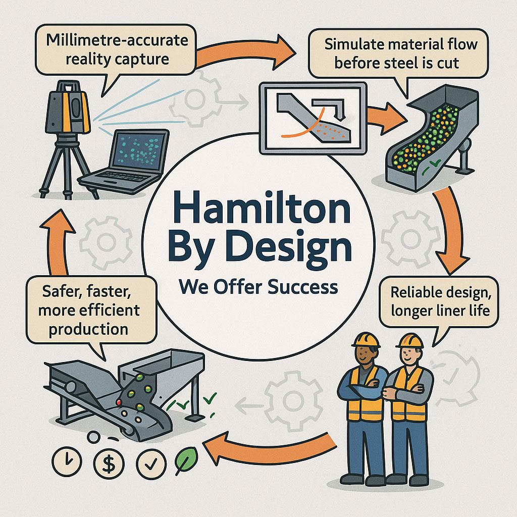
This is exactly where 3D laser scanning in Singleton and Hunter regions is transforming project workflows. Hamilton By Design provides millimetre-accurate digital capture that eliminates guesswork and supports engineering, fabrication, maintenance and shutdown planning across the entire industrial sector.

Whether you’re a CHPP superintendent in Singleton, a fabrication manager in Muswellbrook, a maintenance engineer in the Hunter Valley, or a project manager responsible for upgrades across multiple sites, accurate laser scanning has become essential. This article explores why the demand for 3D scanning has surged, how the technology works, and how Hamilton By Design uses it to support safer, more efficient and more reliable outcomes across the Hunter region.


Why Singleton and the Hunter Need 3D Laser Scanning

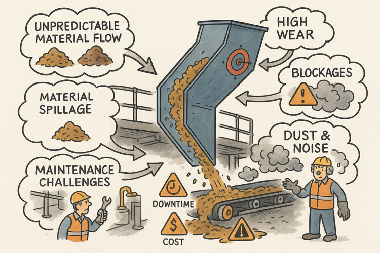
The Hunter region is home to some of Australiaโ€™s most active heavy industrial environments. These operations consist of massive structural steel assemblies, conveyors, process equipment, platforms, chutes, bins and pipework โ€” all subject to wear, deformation and ongoing modification. Many facilities were built long before digital documentation became standard. As a result:

  • Original drawings rarely reflect the current condition
  • Measurements taken by hand are slow, risky and often inaccurate
  • Shutdown windows are extremely tight
  • Brownfield constraints make new installations complex
  • Fabricators rely heavily on accurate data to ensure perfect fitment

Incorrect measurements donโ€™t just cause inconvenience โ€” they create costly fabrication errors, installation delays, safety risks and additional shutdown time.

3D laser scanning removes these risks entirely by creating a verified digital record of what is actually on site.


What 3D Laser Scanning Delivers

Hamilton By Design uses engineering-grade LiDAR scanners to capture millions of precise data points across a site. These points form a point cloud, which is a detailed 3D representation of the real environment. This data can then be used to create accurate models, drawings, simulations and digital checks.

With 3D laser scanning in Singleton and Hunter you get:

  • Accurate as-built geometry
  • Digital templates for fabrication
  • Reliable interface points for new steel or equipment
  • Precise alignment and clearance data
  • Clash identification before installation
  • Improved shutdown planning and safety

For engineers, fitters, boilermakers and fabricators, this accuracy becomes the foundation for smarter decision-making and better project outcomes.


Key Industries Using 3D Laser Scanning in Singleton and the Hunter

1. Mining & CHPP Operations

Singleton is surrounded by some of the most productive mines in the country. Mines and CHPP operations rely heavily on scanning for:

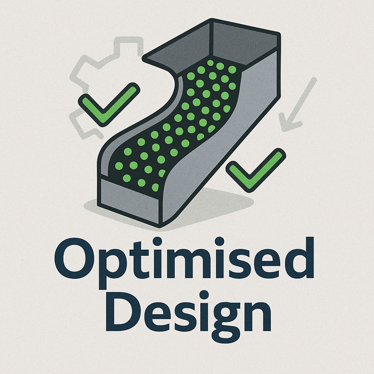
  • Chute and hopper replacements
  • Conveyor alignment checks
  • Transfer tower redesigns
  • Structural integrity assessments
  • Bin, screen and crusher upgrades
  • Digital twins for long-term planning

Because these plants operate continuously, shutdown windows are limited. Laser scanning allows accurate pre-planning, reducing time spent onsite during shutdowns and eliminating unexpected clashes.


2. Fabrication & Manufacturing

The Hunter has a strong fabrication industry, supplying steel structures, mechanical components, platforms, tanks and pipework to mining and energy clients. But fabrication quality relies on measurement quality.

3D laser scanning ensures:

  • Components fit the first time
  • Bolt holes align correctly
  • Flanges match perfectly
  • Structural steel connects without modification
  • Expensive rework on site is eliminated

Workshops across Singleton, Muswellbrook, Thornton and Rutherford increasingly depend on digital accuracy to remain competitive.


3. Power Stations & Energy Infrastructure

The Hunter region includes major power generation assets and critical energy infrastructure. Many structures are ageing, and modifications require absolute accuracy.

Laser scanning supports:

  • Platform replacements
  • Pipe rerouting
  • Structural upgrades
  • Boiler house modifications
  • Maintenance planning
  • Deformation analysis

Reliable as-built data ensures compliance and reduces risk during shutdowns.


4. Industrial, Civil and Commercial Upgrades

Singletonโ€™s industrial footprint is expanding, and many facilities require:

  • As-built documentation
  • Renovations and extensions
  • Spatial coordination
  • Facility redevelopment
  • BIM integration

Laser scanning provides the foundation for safe and efficient project planning across commercial and industrial facilities.


The Hamilton By Design Workflow

Hamilton By Design offers a complete digital engineering solution, from scanning to modelling to fabrication-ready drawings. Our workflow includes:

1. On-Site Scanning

We capture every detail โ€” structural steel, mechanical equipment, conveyors, platforms, bins, hoppers, pipework and building geometry.

2. Processing & Registration

Individual scans are stitched together into a single, accurate point cloud representing the full environment.

3. CAD Modelling

We convert point cloud data into:

  • 3D models
  • GA drawings
  • Fabrication details
  • DXF files for laser cutting
  • Assembly and installation references

4. Digital Fit Checks

Before fabrication begins, we overlay new designs to check for:

  • Clashes
  • Misalignments
  • Interference with existing structures
  • Access and maintenance constraints

5. Project Delivery

Clients receive data that supports safe installation and reduces downtime.


Benefits of 3D Laser Scanning in Singleton and the Hunter

Reduced Rework

Accurate digital data means fabricators build with confidence and installers avoid modifications on site.

Safer Data Capture

Laser scanning reduces the need for manual measuring in hazardous areas.

Faster Shutdown Execution

Pre-planning with accurate data speeds up installation and reduces plant downtime.

Improved Engineering and Design

Designers work from verified geometry rather than guessing from old drawings.

Better Communication

Point clouds and 3D models allow all stakeholders to visualise the site clearly.

Cost Savings from Start to Finish

Less rework, fewer delays and more efficient fabrication combine to deliver real financial value.


Why Choose Hamilton By Design?

Hamilton By Design is uniquely positioned to support Singleton and Hunter clients because:

  • We combine laser scanning expertise with real engineering capability
  • We understand mining, CHPP, fabrication and industrial environments
  • We provide end-to-end digital workflows, not just raw data
  • Our models and drawings are created with fabrication and installation in mind
  • We deliver millimetre-accurate results you can trust

Our team works closely with mine sites, fabricators, energy providers and industrial operators across the region, delivering practical solutions built on real data.


Hamilton By Design logo displayed on a blue tilted rectangle with a grey gradient background

Work With Hamilton By Design

If your project requires precise measurement, modelling, redesign or fabrication, 3D laser scanning in Singleton and the Hunter is the most reliable way to ensure accuracy and reduce risk.

Hamilton By Design is ready to support your next upgrade, shutdown, replacement or maintenance campaign with:

  • On-site laser scanning
  • Point cloud processing
  • CAD modelling
  • Fabrication drawings
  • Digital engineering support

Reach out to discuss your upcoming project โ€” and experience the confidence that only accurate, high-quality 3D data can provide.

Name
Would you like us to arrange a phone consultation for you?
Address

3D Scanning in The Hunter Valley

Hunter Valley Laser Scanning: Transforming Engineering Accuracy Across Mining, Manufacturing and Infrastructure

3D Laser Scanning

3D LiDAR Scanning โ€“ Digital Quality Assurance

Mechanical engineering services
Australian Drafting logo featuring bold white text reading "Australian Drafting" centred on a blue rounded rectangle background.
3D LiDAR scanning and 3D modelling service button โ€” laser scanner capturing a point cloud for engineering and CAD modelling
Mechanical engineering services
Finite Element Analysis (FEA) engineering simulation button
Mechanical engineering services

Chute Design in the Mining Industry

Infographic showing Hamilton By Designโ€™s engineering workflow, including millimetre-accurate LiDAR reality capture, material-flow simulation, optimised chute designs, and safer, more efficient production outcomes. Two workers in PPE highlight reliable design and longer liner life, with icons representing time, cost and quality benefits.

Getting Coal, Hard Rock, and ROM Material Flow Right

Chute design is one of the most critical yet challenging aspects of mining and mineral processing. Whether you are handling coal, hard rock ore, or raw ROM material, chutes and transfer stations are the unsung workhorses of every operation. When designed well, they guide material smoothly, minimise wear, and keep conveyors running. When designed poorly, they cause blockages, spillage, excessive dust, and expensive downtime.

Modern chute design has moved far beyond rules of thumb and back-of-the-envelope sketches. Today, successful projects rely on accurate as-built data, particle trajectory analysis, and advanced Discrete Element Method (DEM) simulation to predict, visualise, and optimise material flow before steel is cut. In this article, we explore why these tools have become essential, how they work together, and where software can โ€” and cannot โ€” replace engineering judgement.


Illustration showing common problems with poorly designed material-handling chutes. A chute discharges material onto a conveyor while issues are highlighted around it: unpredictable material flow, material spillage, maintenance challenges, high wear, blockages, and dust and noise. Warning icons for downtime and cost appear on the conveyor, and workers are shown dealing with the resulting hazards and maintenance tasks.

The Challenge of Chute Design

Coal and hard rock have very different flow behaviours. Coal tends to be softer, generate more dust, and be prone to degradation, while hard rock is more abrasive and can damage chutes if impact angles are not controlled. ROM material adds another level of complexity โ€” oversize lumps, fines, and moisture variation can cause hang-ups or uneven flow.

Chute design must balance several competing objectives:

  • Control the trajectory of incoming material to reduce impact and wear
  • Prevent blockages by maintaining flowability, even with wet or sticky ore
  • Manage dust and noise to meet environmental and workplace health requirements
  • Fit within existing plant space with minimal modification to conveyors and structures
  • Be maintainable โ€” liners must be accessible and replaceable without excessive downtime

Meeting all these goals without accurate data and simulation is like trying to design in the dark.


Illustrated graphic showing a tripod-mounted 3D laser scanner capturing millimetre-accurate as-built data in an industrial plant with conveyors and walkways. Speech bubbles highlight issues such as โ€œOutdated drawings donโ€™t tell the full storyโ€ and โ€œModifications rarely get documented.โ€ The scan data is shown being visualised on a laptop, with notes describing full coverage of conveyors, walkways, and services. Benefits listed along the bottom include faster data collection, fewer site revisits, safer shutdowns, accurate starting point for design simulation, and safer outcomes that ensure designs fit first time.

Capturing the Truth with 3D Scanning

The first step in any successful chute project is to understand the as-built environment. In many operations, drawings are outdated, modifications have been made over the years, and the real plant geometry may differ from what is on paper. Manual measurement is slow, risky, and often incomplete.

This is where 3D laser scanning changes the game. Using tripod-mounted or mobile LiDAR scanners, engineers can capture the entire transfer station, conveyors, surrounding steelwork, and services in a matter of hours. The result is a dense point cloud with millimetre accuracy that reflects the true state of the plant.

From here, the point cloud is cleaned and converted into a 3D model. This ensures the new chute design will not clash with existing structures, and that all clearances are known. It also allows maintenance teams to plan safe access for liner change-outs and other work, as the scanned model can be navigated virtually to check reach and access envelopes.


Understanding Particle Trajectory

Once the physical environment is known, the next challenge is to understand the particle trajectory โ€” the path that material takes as it leaves the head pulley or previous transfer point.

Trajectory depends on belt speed, material characteristics, and discharge angle. For coal, fine particles may spread wider than the coarse fraction, while for ROM ore, large lumps may follow a ballistic path that needs to be controlled to prevent impact damage.

Accurately modelling trajectory ensures that the material enters the chute in the right location and direction. This minimises impact forces, reducing wear on liners and avoiding the โ€œsplashโ€ that creates spillage and dust. It also prevents the material from hitting obstructions or dead zones that could lead to build-up and blockages.

Modern software can plot the trajectory curve for different loading conditions, providing a starting point for chute geometry. This is a critical step โ€” if the trajectory is wrong, the chute design will be fighting against the natural path of the material.


The Power of DEM Simulation

While trajectory gives a first approximation, real-world flow is far more complex. This is where Discrete Element Method (DEM) simulation comes into play. DEM models represent bulk material as thousands (or millions) of individual particles, each following the laws of motion and interacting with one another.

When a DEM simulation is run on a chute design:

  • You can visualise material flow in 3D, watching how particles accelerate, collide, and settle
  • Impact zones become clear, showing where liners will wear fastest
  • Areas of turbulence, dust generation, or segregation are identified
  • Build-up points and potential blockages are predicted

This allows engineers to experiment with chute geometry before fabrication. Angles can be changed, ledges removed, and flow-aiding features like hood and spoon profiles or rock-boxes optimised to achieve smooth, controlled flow.

For coal, DEM can help ensure material lands gently on the receiving belt, reducing degradation and dust. For hard rock, it can ensure that the energy of impact is directed onto replaceable wear liners rather than structural plate. For ROM ore, it can help prevent oversize lumps from wedging in critical locations.


Illustration of an optimised chute design showing material flow represented by green particles, with check marks and gear icons indicating improved efficiency and engineered performance.

๐Ÿ–ฅ Strengths and Limitations of Software

Modern DEM packages are powerful, but they are not magic. Software such as EDEM, Rocky DEM, or Altairโ€™s tools can simulate a wide range of materials and geometries, but they rely on good input data and skilled interpretation.

Key strengths include:

  • Ability to model complex, 3D geometries and particle interactions
  • High visualisation power for communicating designs to stakeholders
  • Capability to run multiple scenarios (different feed rates, moisture contents, ore types) quickly

However, there are limitations:

  • Material calibration is critical. If the particle shape, friction, and cohesion parameters are wrong, the results will not match reality.
  • Computational cost can be high โ€” detailed simulations of large chutes with millions of particles may take hours or days to run.
  • Engineering judgement is still needed. Software will not tell you the โ€œbestโ€ design โ€” it will only show how a proposed design behaves under given conditions.

Thatโ€™s why DEM is best used as part of a holistic workflow that includes field data, trajectory analysis, and experienced design review.


From Model to Real-World Results

When the simulation results are validated and optimised, the design can be finalised. The point cloud model ensures the chute will fit in the available space, and the DEM results give confidence that it will perform as intended.

This means fabrication can proceed with fewer changes and less risk. During shutdown, installation goes smoothly, because clashes have already been resolved in the digital model. Once commissioned, the chute delivers predictable flow, less spillage, and longer liner life.


Why It Matters More Than Ever

Todayโ€™s mining operations face tighter production schedules, stricter environmental compliance, and increasing cost pressures. Downtime is expensive, and the margin for error is shrinking.

By combining 3D scanning, trajectory modelling, and DEM simulation, operations can move from reactive problem-solving to proactive improvement. Instead of waiting for blockages or failures, they can design out the problems before they occur, saving both time and money.


Partnering for Success

At Hamilton by Design, we specialise in turning raw site data into actionable insights. Our team uses advanced 3D scanning to capture your transfer stations with precision, builds accurate point clouds and CAD models, and runs calibrated DEM simulations to ensure your new chute design performs from day one.

Whether youโ€™re working with coal, hard rock, or ROM ore, we help you deliver designs that fit first time, reduce maintenance headaches, and keep production running.

Contact us today to see how our integrated scanning and simulation workflow can make your next chute project safer, faster, and more reliable.

Mechanical Engineering | Structural Engineering

Mechanical Drafting | Structural Drafting

3D Laser Scanning | 3D CAD Modelling | 3D Scanning

Chute Design

SolidWorks Contractors in Australia

Hamilton By Design โ€“ Blog

Consulting Engineers

About Us โ€“ Hamilton By Design

Hamilton By Design | 3D Scanning | Sydney | Perth | Brisbane | Mount Isa | Lidar Scanning

Contact us

3D CAD Modelling Australia service banner for Hamilton By Design
3D LiDAR scanning and 3D modelling service button โ€” laser scanner capturing a point cloud for engineering and CAD modelling
Mechanical engineering services
3D CAD Modelling Australia service banner for Hamilton By Design
Mechanical, Structural & Pipework Drafting service banner by Hamilton By Design featuring white text on a blue background.
Australian Drafting logo featuring bold white text reading "Australian Drafting" centred on a blue rounded rectangle background.
Blue banner graphic displaying the text "Point Cloud to CAD - Australia" in large white lettering, representing point cloud processing, scan-to-CAD conversion and digital engineering services across Australia.
CHPP Engineering title graphic featuring bold white text reading "CHPP Engineering" centred on a blue rounded rectangle background.
Engineering Governance title graphic featuring bold white text reading "Engineering Governance" centred on a blue rounded rectangle background.
Mechanical engineering services
Australian Drafting logo featuring bold white text reading "Australian Drafting" centred on a blue rounded rectangle background.
3D LiDAR Scanning Hunter & Newcastle banner with white text on a blue background promoting engineering-grade laser scanning services for industrial, mining and infrastructure projects across the Hunter Valley and Newcastle region.
Mechanical Engineering Hunter & Newcastle banner promoting mechanical engineering services for mining, industrial plants, power generation, manufacturing and heavy industry throughout the Hunter Valley and Newcastle region.
Structural Drafting Hunter & Newcastle banner promoting structural drafting services for mining, industrial plants, power generation, manufacturing and infrastructure projects across the Hunter Valley and Newcastle region.
Mechanical Engineering Perth WA banner for Hamilton By Design featuring white text on a blue background.
3D Laser Scanning Perth WA banner for Hamilton By Design with white text on a blue background.
SolidWorks Perth WA banner for Hamilton By Design featuring white text on a blue background.
Fabrication and product design services
Finite Element Analysis (FEA) engineering simulation button
3D LiDAR scanning and 3D modelling service button โ€” laser scanner capturing a point cloud for engineering and CAD modelling
Blue rounded button with the text โ€œSolidWorks Designโ€ in white.
Mechanical drafting services button
Structural drafting services button