Port Macquarie Manufacturing & Industrial Engineering

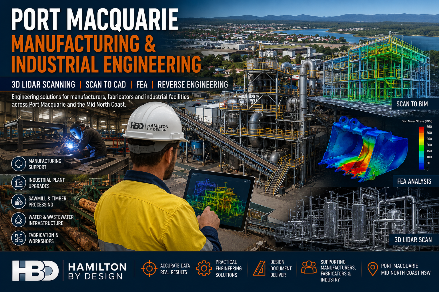
Port Macquarie manufacturing and industrial engineering services featuring 3D LiDAR scanning, Scan to BIM, FEA analysis, fabrication support and industrial plant upgrades by Hamilton By Design.

Port Macquarie Manufacturing & Industrial Engineering

Engineering Solutions for Manufacturers, Fabricators & Industrial Facilities Across the Mid North Coast

Hamilton By Design provides engineering-led mechanical engineering, 3D LiDAR scanning, Scan to CAD, Scan to BIM, reverse engineering, finite element analysis (FEA) and engineering drafting services throughout Port Macquarie, Wauchope, Kempsey, Southwest Rocks, Laurieton and the wider Mid North Coast region.

The Port Macquarie region is home to a growing manufacturing and industrial sector that supports timber processing, food manufacturing, fabrication workshops, transport operators, water infrastructure, marine industries and industrial processing facilities.

As facilities grow and equipment ages, accurate engineering information becomes critical for maintaining productivity, reducing downtime and planning future upgrades.

Hamilton By Design helps manufacturers, engineers, fabricators and asset owners capture existing conditions, develop accurate engineering models and deliver practical solutions for brownfield and greenfield projects.

Whether your project involves upgrading a sawmill, replacing ageing equipment, scanning a processing plant, developing fabrication drawings or validating a design using Finite Element Analysis, our team provides practical engineering support backed by decades of industry experience.


Engineering Services for Manufacturers

Supporting Manufacturing Growth Across Port Macquarie

Manufacturing businesses face increasing pressure to improve productivity, reduce maintenance costs and modernise existing facilities.

Hamilton By Design supports manufacturers by providing:

  • Mechanical Engineering
  • Equipment Design
  • Plant Layout Design
  • Reverse Engineering
  • Engineering Drafting
  • 3D Laser Scanning
  • Scan to CAD
  • Finite Element Analysis
  • Asset Documentation
  • Brownfield Upgrade Support

Our engineering services help manufacturers make informed decisions based on accurate site information and engineering data.


Industrial Plant Engineering

Engineering Support for Existing Facilities

Many industrial facilities have evolved over decades through multiple modifications and expansions.

Unfortunately, original drawings often no longer reflect actual site conditions.

Hamilton By Design provides engineering solutions that allow businesses to accurately document and understand their facilities before commencing upgrades or maintenance projects.

Typical facilities include:

  • Manufacturing Plants
  • Timber Processing Facilities
  • Food Processing Facilities
  • Water Treatment Plants
  • Wastewater Facilities
  • Recycling Facilities
  • Quarry Operations
  • Industrial Workshops
  • Processing Plants

3D LiDAR Scanning Port Macquarie

Engineering Grade Reality Capture

Hamilton By Design provides engineering-grade terrestrial laser scanning services that capture millions of highly accurate measurements.

Laser scanning creates an accurate digital representation of existing facilities and equipment, allowing engineering teams to design with confidence.

Applications include:

  • Manufacturing Facilities
  • Industrial Plants
  • Sawmills
  • Warehouses
  • Water Infrastructure
  • Processing Facilities
  • Structural Steel
  • Pipework Systems
  • Mechanical Equipment

Deliverables include:

  • E57 Files
  • RCP Files
  • RCS Files
  • LAS Files
  • Registered Point Clouds
  • Existing Condition Models
  • Engineering Drawings

Sawmill & Timber Processing Engineering

Supporting Brownfield Upgrades

The Mid North Coast has a long history of timber processing and sawmill operations.

Many facilities have grown over decades and contain a mixture of original equipment, modifications and undocumented changes.

Hamilton By Design supports sawmill operators with:

  • Existing Condition Surveys
  • 3D Laser Scanning
  • Conveyor Design
  • Structural Modifications
  • Dust Extraction Upgrades
  • Equipment Replacement Projects
  • Scan to CAD Services
  • Engineering Documentation

Laser scanning enables accurate modelling of existing plant conditions, reducing project risk and improving installation outcomes.


Scan to CAD Services

Converting Reality into Engineering Information

Point cloud data becomes significantly more valuable when converted into usable engineering deliverables.

Hamilton By Design converts laser scan data into:

  • AutoCAD Drawings
  • Plant Layouts
  • General Arrangement Drawings
  • Equipment Layout Drawings
  • Structural Drawings
  • Mechanical Drawings
  • Fabrication Drawings

These deliverables assist engineers, fabricators and project teams during design and construction activities.


Scan to BIM Services

Building Information Modelling for Existing Assets

Hamilton By Design develops BIM models from laser scan data to support engineering, construction and asset management projects.

We develop BIM models for:

  • Buildings
  • Infrastructure
  • Industrial Facilities
  • Processing Plants
  • Utilities
  • Manufacturing Facilities
  • Water Treatment Facilities
  • Government Assets

Benefits include:

  • Improved project coordination
  • Reduced design clashes
  • Improved construction planning
  • Better asset management
  • Digital Twin Development
  • Enhanced lifecycle management

For industrial facilities and manufacturing operations, Scan to BIM provides an accurate digital foundation for future upgrades and expansion projects.


Mechanical Engineering Services

Practical Engineering Solutions

Hamilton By Design provides mechanical engineering services focused on practical, buildable and maintainable outcomes.

Services include:

  • Mechanical Design
  • Equipment Design
  • Conveyor Design
  • Chute Design
  • Hopper Design
  • Materials Handling Systems
  • Structural Interfaces
  • Equipment Modifications
  • Design Reviews
  • Shutdown Engineering

Our experience spans manufacturing, mining, industrial processing and infrastructure projects throughout Australia.


Finite Element Analysis (FEA)

Engineering Validation Before Fabrication

Finite Element Analysis allows engineers to assess how components and structures perform under load before manufacturing begins.

Hamilton By Design provides FEA services for:

Loader Buckets

Assessment of:

  • Wear zones
  • Reinforcement design
  • Fatigue performance
  • Structural adequacy

Excavator Buckets

Analysis of:

  • Impact loading
  • Structural integrity
  • Wear protection systems
  • Load distribution

Grader Blades

Verification of:

  • Structural support systems
  • Ground engagement loads
  • Deflection performance
  • Wear areas

Chutes & Hoppers

Evaluation of:

  • Material loading
  • Structural performance
  • Impact zones
  • Reinforcement requirements

Industrial Structures

Assessment of:

  • Platforms
  • Walkways
  • Equipment Supports
  • Access Systems
  • Structural Frames

FEA provides confidence that designs will perform safely and efficiently under operational conditions.


Reverse Engineering Services

Recreating Existing Assets

When original engineering drawings are unavailable, reverse engineering can recover valuable engineering information.

Hamilton By Design provides reverse engineering services for:

  • Mechanical Components
  • Pumps
  • Shafts
  • Castings
  • Conveyor Components
  • Wear Liners
  • Structural Components
  • Machinery Assemblies

Deliverables include:

  • SolidWorks Models
  • STEP Files
  • SAT Files
  • Fabrication Drawings
  • Manufacturing Drawings

Engineering Drafting Services

Professional Documentation for Construction & Fabrication

Our drafting services provide accurate engineering documentation for manufacturing, industrial and infrastructure projects.

Services include:

  • Mechanical Drafting
  • Structural Drafting
  • Fabrication Drawings
  • Workshop Drawings
  • As-Built Drawings
  • Construction Documentation
  • Plant Layout Drawings

Using:

  • SolidWorks
  • Autodesk Inventor
  • AutoCAD
  • Navisworks
  • FARO SCENE
  • Autodesk ReCap

Why Choose Hamilton By Design?

Engineering-Led Approach

We understand how engineering information is used throughout the project lifecycle.

Practical Industry Experience

Experience supporting:

  • Manufacturers
  • Fabricators
  • Mining Operations
  • Industrial Facilities
  • Utilities
  • Infrastructure Owners

Advanced Technology

Including:

  • FARO Focus Laser Scanners
  • FARO Orbis Mobile Scanning
  • FARO SCENE
  • SolidWorks
  • ANSYS
  • Autodesk Inventor
  • AutoCAD
  • Navisworks

Australia-Wide Capability

Supporting projects across:

  • Port Macquarie
  • Mid North Coast
  • Newcastle & Hunter
  • Sydney
  • Brisbane
  • Melbourne
  • Adelaide
  • Perth

Hamilton By Design logo displayed on a blue tilted rectangle with a grey gradient background

Need Engineering Support in Port Macquarie?

Whether your project involves manufacturing facilities, industrial plants, sawmills, water infrastructure or brownfield upgrades, Hamilton By Design provides practical engineering solutions backed by real industry experience.

Our Services

โœ” Manufacturing Engineering
โœ” Industrial Engineering
โœ” Mechanical Engineering
โœ” 3D LiDAR Scanning
โœ” Scan to CAD
โœ” Scan to BIM
โœ” Reverse Engineering
โœ” Finite Element Analysis (FEA)
โœ” Engineering Drafting
โœ” Sawmill Engineering Support
โœ” Industrial Plant Upgrades
โœ” Brownfield Engineering Projects

Talk to Us – Contact Us

Name
Would you like us to arrange a phone consultation for you?
Address

Our clients:
3D LiDAR Scanning Darwin for engineering surveys, laser scanning, reality capture and point cloud modelling services
3D LiDAR Scanning Australia engineering services for laser scanning, reality capture, scan-to-CAD, Scan-to-BIM and as-built documentation across Australia
3D LiDAR scanning services on the Central Coast providing engineering-grade laser scanning, point cloud capture, scan-to-CAD modelling and industrial reality capture for infrastructure and industrial projects.

SolidWorks FEA Simulation

SolidWorks FEA Simulation

At Hamilton By Design, we use SolidWorks Simulation FEA to help mining, manufacturing, power generation and industrial clients make better decisions before anything is cut, welded or installed.

Whether youโ€™re upgrading a chute, checking a pressure vessel, or validating a complex brownfield retrofit, our team can simulate real-world loads, temperatures and constraints so you know how your design will behave in service.


Why use SolidWorks FEA with Hamilton By Design?

  • Mechanical engineers with real site experience โ€“ CHPPs, conveyors, reclaimers, pressure vessels, structures and plant equipment.
  • Seamless link to 3D CAD โ€“ we model in SolidWorks, analyse in SolidWorks Simulation, then deliver fabrication-ready drawings.
  • Engineering-grade results โ€“ correct boundary conditions, meshing control and code-aligned assessment where required.
  • Clear reports for decision-makers โ€“ not just stress plots, but explanations, factors of safety and practical recommendations.

Our SolidWorks FEA Capabilities

We offer a broad range of analysis types, from straightforward linear static checks through to advanced contact, thermal and fatigue studies.

1. Linear Static & Structural Integrity

For components and assemblies under static loading:

  • Linear Static (parts and assemblies)
  • Linear Static โ€“ multi-body assemblies
  • Beam and Shell element models for frames, platforms, platework and tanks
  • Static Stress (parts)
  • Static Stress (assemblies)
  • Contacts and contact sets (bonded, no-penetration, friction etc.)
  • Large displacement behaviour for flexible or slender structures

Typical use cases:

  • Platforms, walkways, supports, frames
  • Brackets, bases, machine frames and guarding
  • Brownfield modifications and tie-ins

2. Modal, Frequency & Buckling Analysis

Understanding how structures respond to vibration and instability:

  • Frequency / Modal analysis
  • Modal / Frequency analysis (eigenfrequencies and mode shapes)
  • Buckling Analysis (eigenvalue / linear buckling)
  • Modal / Buckling studies for slender structures

Typical use cases:

  • Avoiding resonance in platforms, ducts, chutes and pipework
  • Screening structures against equipment running speeds
  • Checking risk of buckling under compressive loads

3. Thermal Analysis (Steady & Transient)

Thermal loading can be just as critical as mechanical loading. We perform:

  • Steady State Thermal analysis
  • Transient Thermal analysis
  • Coupled thermalโ€“stress workflows (temperature โ†’ stress)

Typical use cases:

  • Hot chutes, ducts, kilns and enclosures
  • Equipment in high-temperature environments
  • Evaluating thermal gradients prior to stress assessment

4. Fatigue & Life Estimation

Assessing how long components are likely to last under cyclic loading:

  • Fatigue analysis using Stress-Life (SN curves)
  • Fatigue Analysis / Fatigue (SN Curves)
  • Fatigue โ€“ Stress-Life (SN curves) for variable loading conditions

Typical use cases:

  • High-cycle fatigue in vibrating plant and supports
  • Welded details on chutes, frames and platforms
  • Repeated loading on mechanical components

5. Drop Test & Impact-Type Events

Where equipment may be dropped, impacted or experience short-duration loads:

  • Drop Test simulations (rigid and flexible bodies)
  • Drop Test (explicit-like method within SolidWorks Simulation)

Typical use cases:

  • Handling frames, lifting devices, skids
  • Enclosures, housings and protective covers
  • Equipment subject to accidental drop or impact

6. Pressure Vessel & Stress Linearisation

We support pressure vessels and pressurised equipment with:

  • Pressure Vessel evaluation
  • Pressure Vessel / Stress Linearization for membrane and bending stress extraction
  • Assessment against design criteria (in conjunction with relevant codes/standards as required)

Typical use cases:

  • Tanks, vessels, pipework branches and nozzles
  • Pressure retaining components in process plants

7. Topology Optimisation & Design Refinement

For weight reduction and concept development:

  • Topology Optimisation for parts and sub-assemblies
  • Using optimisation results to drive manufacturable designs in SolidWorks

Typical use cases:

  • Lightweight brackets and frames
  • Concept development where weight, stiffness or cost must be balanced

8. Motion & Load Extraction

Understanding motion and using it to drive realistic FEA loads:

  • Time-based Motion studies
  • Load extraction from motion into FEA (reaction forces, accelerations, etc.)

Typical use cases:

  • Mechanisms with moving arms, linkages or tooling
  • Equipment where dynamic loads dominate over static loads

9. Advanced Contacts, Meshing & Convergence

Robust results rely on correct discretisation and contact definition. We provide:

  • Advanced Contacts (nonlinear contact behaviour, friction, separation)
  • Advanced meshing strategies for complex geometry
  • Local mesh refinement around welds, holes, notches and stress raisers
  • Mesh convergence checks for confidence in results

Reporting & Engineering Documentation

Every simulation is backed by clear, traceable documentation, including:

  • Description of the model, loads, boundary conditions and assumptions
  • Material properties and factors of safety used
  • Key plots: stress, displacement, factor of safety, temperature, modes, buckling shapes etc.
  • Fatigue life estimates where applicable
  • Mesh screenshots and convergence discussion
  • Practical engineering recommendations (e.g. increase plate thickness, add stiffeners, adjust weld details).

These reports can be issued in PDF format for internal review, client submissions or integration into your broader design dossier.


How We Work With You

  1. Define the problem โ€“ loads, constraints, operating conditions and success criteria.
  2. Build or import the CAD model โ€“ we model in SolidWorks or clean up your existing geometry.
  3. Set up the study โ€“ select the appropriate FEA type, materials, contacts and mesh.
  4. Run and refine โ€“ iterate as needed to achieve stable, converged results.
  5. Recommend improvements โ€“ we help you interpret the results and adjust the design.
  6. Deliver documentation โ€“ final models, plots and reports ready for approval or fabrication.

Discuss Your Next SolidWorks FEA Project

If you need confidence that your design will perform as intended โ€“ whether itโ€™s a small bracket or a critical plant upgrade โ€“ our team can help.

Hamilton By Design combines SolidWorks FEA simulation with practical engineering and fabrication understanding to de-risk projects across mining, heavy industry, power generation and manufacturing.

Get in touch to discuss your next project, share a model, or explore whether FEA can help you solve a specific problem before it becomes a shutdown headache.


Hamilton By Design logo displayed on a blue tilted rectangle with a grey gradient background
3D LiDAR scanning and 3D modelling service button โ€” laser scanner capturing a point cloud for engineering and CAD modelling
Mechanical engineering services

Our clients:

Name
Would you like us to arrange a phone consultation for you?
Address

Further Reading


Finite Element Analysis (FEA) engineering simulation button
Mechanical engineering services

Engineering Confidence: Using FEA to Validate Real-World Designs

Mechanical engineering has always been a balance between creativity and certainty.
Every bracket, frame, chute, or structural support we design must perform under real loads, temperatures, and conditions โ€” often in environments where failure simply isnโ€™t an option.

Thatโ€™s where Finite Element Analysis (FEA) earns its place as one of the most powerful tools in modern design. It allows engineers to move from assumption to verification โ€” transforming the way we predict, test, and optimise mechanical systems.


What Is FEA โ€” and Why It Matters

FEA divides complex geometry into a network of small, interconnected elements.
By solving the physical equations that govern stress, strain, and displacement across those elements, engineers can predict how a structure behaves under load, vibration, or temperature.

Instead of relying solely on hand calculations or over-built safety factors, FEA provides quantitative insight into performance โ€” letting us see where structures flex, where stress concentrates, and how design choices affect real-world outcomes.

In mechanical engineering, that means fewer prototypes, lower material costs, and far greater design confidence.


1. Static Analysis โ€” The Foundation of Structural Validation

Static linear analysis is the foundation of most FEA work.
It evaluates how a structure responds to steady, time-independent loads such as gravity, pressure, or fixed equipment weight.

Through static analysis, engineers can:

  • Visualise stress and displacement distribution across a part or assembly.
  • Evaluate safety factors under different loading conditions.
  • Check stiffness and material utilisation before fabrication.
  • Identify weak points or stress concentrations early in design.

This baseline validation is the difference between a design that โ€œshouldโ€ work and one that will.


2. Assembly-Level Simulation โ€” Seeing the Whole System

Few machines fail because a single part breaks.
Most failures happen when components interact under load โ€” bolts shear, brackets twist, or welds experience unplanned tension.

FEA allows engineers to simulate entire assemblies, including:

  • Contact between parts (bonded, sliding, or frictional).
  • Realistic boundary conditions such as bearings, springs, or pinned joints.
  • The influence of welds, fasteners, or gaskets on overall performance.

This system-level view helps mechanical engineers design not only for strength, but also for compatibility and reliability across the full structure.


3. Mesh Control โ€” Accuracy Where It Counts

A simulation is only as good as its mesh.
By controlling element size and density, engineers can capture critical detail in stress-sensitive regions like fillets, bolt holes, and weld toes.

Modern FEA tools use adaptive meshing โ€” refining the model automatically in areas of high stress until the solution converges.
That means precise, efficient results without excessive computation time.


4. Thermal-Structural Interaction โ€” When Heat Becomes a Load

Many mechanical systems face thermal as well as mechanical challenges.
Whether itโ€™s ducting in a process plant or hoppers near heat sources, temperature gradients can cause expansion, distortion, or thermal stress.

FEA allows engineers to:

  • Model steady-state or transient heat transfer through solids.
  • Apply convection, radiation, or temperature boundary conditions.
  • Combine thermal and structural analyses to study thermal expansion and thermal fatigue.

Understanding how heat and load combine helps ensure equipment remains stable, safe, and accurate throughout its lifecycle.


5. Modal and Buckling Analysis โ€” Designing Against Instability

Some risks are invisible until theyโ€™re simulated.
Vibration and buckling are two of the most overlooked โ€” yet most common โ€” causes of structural failure.

Modal Analysis

Determines a structureโ€™s natural frequencies and mode shapes, helping designers avoid resonance with operating machinery, fans, or conveyors.

Buckling Analysis

Predicts the critical load at which slender members or thin-walled panels lose stability โ€” allowing engineers to reinforce and optimise designs early.

By identifying these limits before fabrication, engineers can prevent problems that are expensive and dangerous to discover on site.


Design Optimisation โ€” Smarter, Lighter, Stronger

Good design is rarely about adding material; itโ€™s about using it wisely.
FEA supports parametric and goal-based optimisation, enabling engineers to vary geometry, thickness, or material and automatically test multiple configurations.

You can set objectives such as:

  • Minimising weight while maintaining strength.
  • Reducing deflection under fixed loads.
  • Optimising gusset or flange size for stiffness.

This process of โ€œdigital lightweightingโ€ drives better performance and cost efficiency โ€” especially valuable in industries where both material and downtime are expensive.


7. Communication and Confidence

FEA isnโ€™t only a calculation tool โ€” itโ€™s a communication tool.
Colour-coded plots, animations, and automated reports make it easier to explain complex mechanical behaviour to project managers, clients, or certifying bodies.

Clear visuals turn stress distributions and displacement fields into a shared language โ€” helping stakeholders understand why certain design choices are made.


Real-World Applications Across Mechanical Engineering

ApplicationType of AnalysisKey Benefit
Chutes & HoppersStatic + BucklingConfirm wall thickness and frame design for structural load and vibration
Conveyor FramesModal + StaticAvoid resonance and ensure adequate stiffness
Pressure EquipmentThermal + StaticEvaluate thermal stress and hoop stress under load
Machine BracketsStatic + OptimisationReduce weight while maintaining rigidity
Platforms & GuardingBucklingValidate stability under safety loading
Welded Frames & SupportsStaticCheck deformation, stress, and weld performance

These examples show how FEA becomes an everyday design partner โ€” embedded in the workflow of mechanical engineers across manufacturing, resources, and infrastructure.


The Engineerโ€™s Advantage: Data Over Assumption

In traditional design, engineers often relied on prototypes and conservative safety factors.
Today, simulation delivers the same assurance โ€” without the waste.

By applying FEA early in the design cycle, mechanical engineers can:

  • Predict failure modes before they occur.
  • Shorten development time.
  • Reduce material usage.
  • Justify design decisions with quantitative proof.

FEA enables engineers to focus less on guesswork and more on innovation โ€” designing structures that are both efficient and dependable.


Engineering Integrity in Practice

At Hamilton By Design, we integrate FEA into every stage of mechanical design and development.
Itโ€™s how we ensure that every frame, chute, and mechanical system we deliver performs as intended โ€” safely, efficiently, and reliably.

We use FEA not just to find the limits of materials, but to push the boundaries of design quality โ€” delivering engineering solutions that last in the toughest industrial environments.

Design backed by data isnโ€™t a slogan โ€” itโ€™s how we engineer confidence.


Building a Culture of Verified Design

When FEA becomes part of everyday engineering culture, it changes how teams think.
Designers begin to see structures not just as drawings, but as living systems under real forces.

That shift builds trust โ€” between engineer and client, between concept and reality.
Itโ€™s what defines the future of mechanical design: informed, optimised, and proven before the first bolt is tightened.

3D LiDAR scanning and 3D modelling service button โ€” laser scanner capturing a point cloud for engineering and CAD modelling
Mechanical engineering services
Finite Element Analysis (FEA) engineering simulation button
Mechanical engineering services

3D Scanning Sydney banner promoting engineering-grade 3D laser scanning, LiDAR scanning, and reality capture services by Hamilton By Design.
Mechanical Engineering Sydney banner with white text on a blue background representing Hamilton By Design's mechanical engineering services in Sydney.
Mechanical Drafting and 3D Modelling Sydney banner highlighting Hamilton By Design's CAD drafting, 3D modelling, and engineering design services in Sydney.

Mechanical Engineering | Structural Engineering