

Scan to CAD Perth

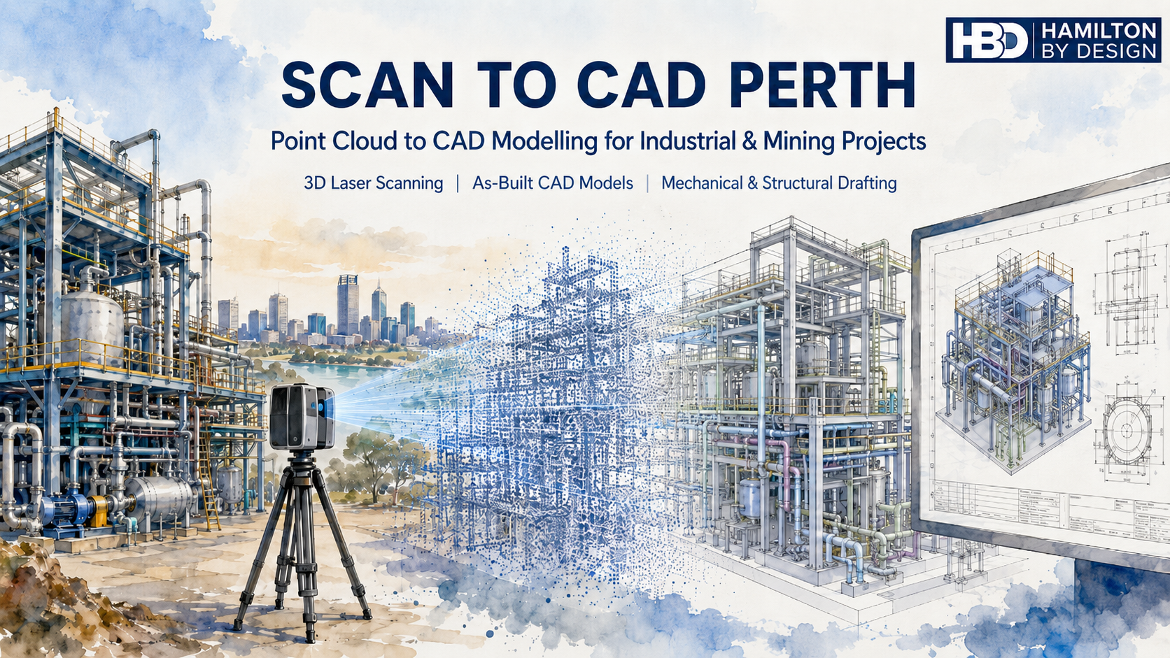
Scan to CAD Perth watercolour hero image showing a 3D laser scanner capturing an industrial plant, converting point cloud data into CAD models and engineering drawings.

Point Cloud to CAD Modelling for Industrial, Mining and Engineering Projects

Blue 3D LiDAR scanner icon on a tripod with scanning waves

Hamilton By Design provides Scan to CAD Perth services for businesses that need accurate CAD models, drawings and engineering information from existing plant, equipment, structures and sites.

Many Perth and Western Australian businesses work with assets that have been modified over many years. Drawings may be missing, outdated, incomplete or no longer trusted. This creates problems when planning upgrades, replacing equipment, modifying pipework, designing new access platforms or reverse engineering obsolete parts.

Scan to CAD helps solve this problem by converting real-world site conditions into usable CAD data.

Using 3D laser scanning and LiDAR capture, Hamilton By Design can scan existing assets and convert the point cloud into practical engineering deliverables such as 3D CAD models, 2D drawings, as-built layouts, mechanical models, structural layouts, pipework models and fabrication-ready documentation.

For related Perth services, Hamilton By Design also provides 3D laser scanning in Perth, mechanical engineering services in Perth and SolidWorks CAD support in Perth.

Our Scan to CAD Perth services support mining, industrial, manufacturing, marine, infrastructure, water, energy and process plant projects across Perth and Western Australia.


What Is Scan to CAD?

Scan to CAD is the process of capturing an existing object, machine, structure, plant room, building or industrial site using a 3D laser scanner, then converting the scan data into CAD models or drawings.

The scanner captures millions of measurement points from the real-world environment. This creates a point cloud, which can then be processed, registered and used as a reference for CAD modelling.

The CAD output may be simple or detailed depending on the project.

For example, a business may need a basic 3D layout to check whether new equipment will fit. Another project may require detailed CAD models of pipework, steelwork, access platforms, pump components or mechanical assemblies. In some cases, the final deliverable may be a set of fabrication drawings, general arrangement drawings, sections, elevations or 3D model files for engineering design.

Scan to CAD is especially useful for brownfield projects, where new design work needs to fit around existing assets.


Why Perth Businesses Use Scan to CAD Services

Perth businesses use Scan to CAD services when they need reliable information about existing assets.

This is common in mining, ports, processing plants, fabrication workshops, pump stations, utilities, marine facilities and industrial sites. Many of these sites have been changed over many years. Equipment has been replaced, pipework has been rerouted, structures have been modified and old drawings may not reflect the current condition.

When drawings cannot be trusted, engineering work becomes risky.

A new piece of equipment may clash with existing steelwork. A replacement pipe spool may not fit. A platform may be designed around incorrect dimensions. A shutdown job may be delayed because the site information was wrong. These problems can cost far more than the original drafting or scanning work.

Scan to CAD helps reduce this risk by giving engineers, project managers, fabricators and maintenance teams a clearer understanding of the existing site before design, fabrication or installation begins.

For larger Perth and WA projects, this service can also connect with Hamilton By Designโ€™s broader Perth WA engineering and 3D scanning services.


Common Problems Scan to CAD Helps Solve

One of the biggest problems businesses face is the lack of reliable drawings. In many industrial environments, original drawings are either unavailable or no longer accurate. This is particularly common where plant has been upgraded over many years without the as-built documentation being updated.

Another common problem is that OEM drawings are not available. Equipment suppliers may not provide drawings, or replacement parts may have long lead times and high costs. In these situations, Scan to CAD can assist with reverse engineering by capturing the existing part or assembly and creating CAD models for review, repair, modification or replacement.

Brownfield upgrades are another major reason for using Scan to CAD. Existing structures, conveyors, chutes, tanks, pumps, platforms, walkways and pipework can make new design work difficult. A scan provides a practical way to model the existing environment and check the proposed design before fabrication.

Shutdown work is also a key driver. During a shutdown, there is limited time to complete installation work. If a fabricated part does not fit, the cost can be significant. Scan to CAD helps reduce the chance of site rework, emergency fabrication and installation delays.


Scan to CAD for Mining and Industrial Sites in Perth

Perth is closely connected to Western Australiaโ€™s mining, resources, marine, energy and industrial sectors. Many projects are designed, managed or supported from Perth, even when the site itself is located elsewhere in WA.

Hamilton By Design supports Scan to CAD services for mining and industrial applications including:

Conveyors, chutes and transfer points.

Pump stations and pipework.

Processing plants and fixed plant equipment.

Access platforms, stairs, ladders and walkways.

Structural steel layouts.

Mechanical equipment and machine components.

Plant rooms and service areas.

Marine and ship repair projects.

Brownfield upgrade areas.

Reverse engineering of obsolete or unavailable parts.

The purpose is not only to create a point cloud. The purpose is to turn that scan data into useful engineering information.

For projects involving steelwork, platforms, pipework or industrial layouts, Hamilton By Design also provides mechanical, structural and pipework drafting in Perth WA.


From Point Cloud to Practical CAD Deliverables

A point cloud is valuable, but many businesses need more than raw scan data. They need usable CAD information that can support decisions, design work, procurement, fabrication and installation.

Hamilton By Design can convert point cloud data into a range of CAD deliverables, including:

3D CAD models.

2D CAD drawings.

General arrangement drawings.

Sections and elevations.

As-built layouts.

Pipework models.

Structural models.

Mechanical models.

STEP, SAT or Parasolid files.

SolidWorks models.

Inventor models.

AutoCAD drawings.

DWG and DXF files.

Fabrication drawings where required.

The final deliverable depends on the project requirement. A clash detection model may not need the same level of detail as a fabrication drawing. A concept model may not need every bolt and weld. A reverse engineering job may need a much higher level of detail.

This is why it is important to define the scope before scanning and modelling begins.


The Importance of Engineering Understanding

Scan to CAD is not just a software process. It requires engineering judgement.

A scanner records what it can see, but the CAD model needs to be interpreted and built by someone who understands the purpose of the work. This is especially important for mechanical, structural and industrial projects.

For example, pipework may need to be modelled using correct pipe outside diameters and centre lines. Steelwork may need to reflect real member sizes. Platforms and access systems may need to consider Australian Standards such as AS 1657. Mechanical components may need to be modelled with design intent, clearances, tolerances and manufacturing method in mind.

A visually impressive model is not always an engineering-ready model.

Hamilton By Design focuses on practical CAD outputs that can be used by engineers, fabricators, project managers and maintenance teams.


Problems Businesses Can Have With Poor Scan to CAD Services

Not all Scan to CAD services are the same.

A common problem is that businesses receive a large point cloud but do not know how to use it. The file may be too large, the format may not suit their software, or the areas they need may not have been captured properly.

Another problem is unclear scope. If the instruction is only โ€œscan the site and provide CADโ€, the result may not match what the business expected. The scope should define what needs to be scanned, what needs to be modelled, the required level of detail, the accuracy expectations, the required file formats and whether drawings are included.

Businesses can also run into trouble when the model is either under-modelled or over-modelled. Under-modelling can miss important details. Over-modelling can waste time and increase cost without adding value.

There can also be line-of-sight issues. Laser scanners cannot see through objects, insulation, guards, cladding or equipment. Hidden areas may require extra scan positions, physical measurement or site verification.

The best results come from planning the scan around the final CAD deliverable.


When Should Scan to CAD Be Used?

Scan to CAD should be considered early in a project, especially when existing information is unreliable.

It is useful before:

Plant upgrades.

Equipment installation.

Shutdown planning.

Pipework replacement.

Structural modification.

Access platform design.

Reverse engineering.

Fabrication.

Clash detection.

Layout planning.

As-built documentation.

The earlier the scan is completed, the more useful it becomes. If the scan is done after design work is already finished, it may only reveal problems late in the project. When scanning is completed early, the design team can work around the real site conditions from the start.


Scan to CAD Perth for Brownfield Engineering

Brownfield engineering is one of the strongest applications for Scan to CAD.

In a brownfield site, the challenge is not simply designing something new. The challenge is making sure the new design fits the existing plant.

This is where Scan to CAD provides value.

By converting existing site conditions into CAD, Hamilton By Design can help identify space restrictions, clashes, tie-in points, access limitations and installation constraints before work reaches site.

This can support better planning, better design decisions and reduced installation risk.

For businesses needing building, facility or infrastructure modelling from scan data, Hamilton By Design also provides Scan to BIM services in Perth WA.


Why Work With Hamilton By Design?

Hamilton By Design combines 3D laser scanning, CAD modelling, mechanical engineering, structural drafting and reverse engineering experience.

This means the Scan to CAD process is approached with the final engineering outcome in mind.

We understand that businesses do not simply need a scan. They need answers.

Will the new equipment fit?

Can the part be reverse engineered?

Can the pipework be modelled accurately?

Can the existing structure be documented?

Can the shutdown risk be reduced?

Can the CAD model be used for design, drafting or fabrication?

Our goal is to provide practical CAD information that helps businesses make better engineering decisions.


Scan to CAD Perth Services

Hamilton By Design provides Scan to CAD Perth services for businesses needing accurate, useful and engineering-focused CAD deliverables from existing assets.

Whether the project involves mining equipment, industrial plant, pipework, structural steel, mechanical components, marine repairs or brownfield upgrades, Scan to CAD can help turn site reality into usable engineering data.

If your business has missing drawings, unreliable site information, obsolete parts, shutdown risk or brownfield design challenges, Scan to CAD may be the right starting point.

Hamilton By Design can assist with 3D laser scanning, point cloud processing, CAD modelling, as-built documentation and engineering drafting for Perth and Western Australian projects.

Hamilton By Design logo displayed on a blue tilted rectangle with a grey gradient background

Need Scan to CAD Support in Perth?

Hamilton By Design provides Scan to CAD services for Perth businesses that need accurate CAD models and drawings from existing plant, equipment and structures.

We can assist with site scanning, point cloud processing, CAD modelling, as-built drawings, reverse engineering and engineering documentation for industrial and mechanical projects.

Talk to Us – Contact Us

Name
Would you like us to arrange a phone consultation for you?
Address

Our clients:

https://www.hamiltonbydesign.com.au/scan-to-bim-services-australia-lidar-point-clouds-cad-modelling

Surface Mine Scan to CAD Hunter Valley NSW

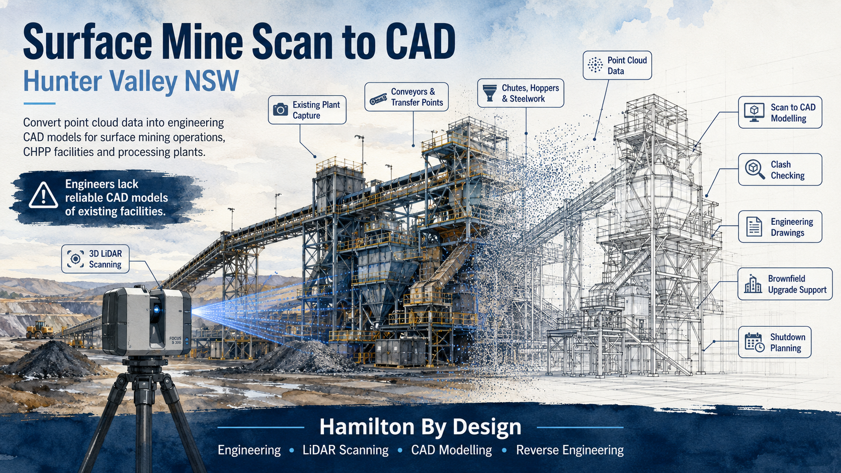
Watercolour hero image showing a Hunter Valley surface mine processing plant being captured by 3D LiDAR scanning and converted from point cloud data into a CAD model.

Convert Point Cloud Data into Engineering CAD Models for Surface Mining Operations and Processing Plants

Blue 3D LiDAR scanner icon on a tripod with scanning waves

Engineers working in surface mining operations across the Hunter Valley are often expected to design upgrades, replacement parts, access structures, chute modifications, conveyor changes and plant improvements without a reliable CAD model of the existing facility. In many cases, the drawings available to the project team are outdated, incomplete, unavailable from the OEM, or no longer match the real site.

That creates a serious problem.

When engineers do not have accurate CAD models of existing plant, every brownfield project begins with uncertainty. A chute may look correct on an old drawing but be different on site. A conveyor support may have been modified during a shutdown. A platform may have been extended. Pipework may have been rerouted. Guards, stairs, handrails, access points and maintenance clearances may no longer match the original design.

For surface mining and processing plant environments, this is where Surface Mine Scan to CAD becomes valuable.

Hamilton By Design supports Hunter Valley mining and industrial operations by converting 3D laser scan and LiDAR point cloud data into practical engineering CAD models. These models help engineers, maintenance teams, shutdown planners and fabricators work from the real condition of the site instead of relying on assumptions.

For broader mining-related engineering support, Hamilton By Design also provides Hunter Valley Mining Engineering & 3D Laser Scanning Services for brownfield plant, CHPP facilities, conveyor infrastructure, structural steelwork and heavy industrial assets.

The Problem: Engineers Lack Reliable CAD Models of Existing Facilities

The biggest issue in many surface mining operations is not always the lack of engineering skill. It is the lack of reliable existing information.

Engineering teams may be highly capable, but if the base model is wrong, the new design can be wrong before it starts. This is a common challenge in brownfield mining environments where plant has been modified, repaired, patched, upgraded and maintained over many years.

Old drawings are often treated as the starting point for a project, but they may not show what is actually installed. In some cases, the OEM will not provide the drawings. In other cases, the equipment has been altered so many times that the original drawing is no longer useful. The plant may have had structural modifications, replacement components, temporary repairs, maintenance improvements or shutdown changes that were never captured in CAD.

This creates risk for:

  • Project engineers
  • Mechanical engineers
  • Structural engineers
  • Drafting teams
  • Maintenance planners
  • Shutdown planners
  • Fabricators
  • Installation contractors
  • Asset owners
  • CHPP and processing plant managers

The result is often the same: more site measuring, more assumptions, more rework and more pressure during installation.

What Is Surface Mine Scan to CAD?

Surface Mine Scan to CAD is the process of capturing existing mining infrastructure using 3D laser scanning or LiDAR, then converting the point cloud into usable engineering CAD models.

A point cloud is a highly detailed digital capture of the physical environment. It records the real position and shape of steelwork, conveyors, platforms, chutes, hoppers, bins, tanks, pumps, pipework, handrails, access stairs, guarding and surrounding plant.

However, a point cloud by itself is not always enough.

Engineers usually need the scan data converted into a CAD format they can use for design, checking, fabrication or installation planning. That may include SolidWorks models, Inventor models, AutoCAD drawings, Navisworks coordination files, STEP files, SAT files, DWG files, DXF files, general arrangement drawings, sections, elevations or fabrication drawings.

The value is not just the scan. The value is turning the scan into engineering information.

Hamilton By Designโ€™s 3D CAD Modelling Australia service supports this exact problem by creating practical 3D models from point clouds, existing drawings, PDFs, sketches, marked-up plans and site measurements.

Why Surface Mining Operations Need Scan to CAD

Surface mining operations are full of existing assets that are difficult to measure accurately by hand. These facilities often include conveyors, transfer stations, crushers, screens, bins, hoppers, CHPP structures, workshops, pump systems, tanks, pipe racks, platforms, walkways and access structures.

Many of these assets are large, complex, elevated, corroded, modified or hard to access safely.

Traditional site measuring can be slow and risky. It may also miss important details. Measuring one beam, one chute or one platform may not capture the full context around the design. A modification may need to clear existing steelwork, match an existing conveyor, avoid pipework, maintain access, fit within guarding and be installed during a short shutdown window.

A 3D laser scan captures the surrounding environment so the design team can work with a much better understanding of the real plant.

For surface mine engineers, Scan to CAD can assist with:

  • Brownfield upgrades
  • Chute replacement and redesign
  • Conveyor modifications
  • Transfer station upgrades
  • Structural steel checks
  • Access platform upgrades
  • Pump and pipework changes
  • Plant layout verification
  • Clash detection
  • Shutdown planning
  • Reverse engineering
  • Fabrication support
  • As-built documentation
  • Replacement parts where OEM drawings are unavailable

Location Focus: Hunter Valley NSW

The Hunter Valley is one of the most important mining and industrial regions in New South Wales. For engineering teams working around surface mining operations, coal handling plants, processing facilities and associated infrastructure, the need for accurate site information is ongoing.

Hamilton By Design supports engineering-led Scan to CAD workflows across the Hunter Valley and surrounding NSW mining regions.

Towns and regional areas serviced

The following town and regional names are relevant to the Hunter Valley surface mining and industrial service area:

  • Muswellbrook
  • Singleton
  • Maitland
  • Cessnock
  • Newcastle
  • Rutherford
  • Kurri Kurri
  • Branxton
  • Greta
  • Denman
  • Aberdeen
  • Scone
  • Warkworth
  • Mount Thorley
  • Ravensworth
  • Camberwell
  • Broke
  • Pokolbin
  • Bulga
  • Jerryโ€™s Plains
  • Liddell
  • Wybong
  • Upper Hunter
  • Lower Hunter
  • Hunter Valley NSW

These locations are listed as service-region references only and are not intended to connect any individual mine to a specific town.

Mine and operation names in the broader region

The following mine and operation names are relevant when discussing surface mining, coal handling, processing plant and engineering activity in the Hunter Valley and surrounding NSW coal regions:

  • Hunter Valley Operations / HVO
  • HVO North
  • HVO South
  • Mount Arthur Coal Mine
  • Mangoola Open Cut
  • Mount Pleasant Operation
  • Bengalla Mine
  • Ravensworth Operations
  • Mount Owen Complex
  • Glendell Mine
  • Rixโ€™s Creek Mine
  • Bulga Coal
  • Warkworth Mine
  • Mount Thorley Mine
  • United Wambo
  • United Mine
  • Wambo Mine
  • Ashton Coal
  • Integra Underground
  • Maxwell Underground Mine
  • Dartbrook Mine
  • Liddell Open Cut
  • Muswellbrook Coal
  • Muswellbrook No. 2

These mine names are listed separately from the town names. They are included to help describe the broader regional mining context and the type of industrial infrastructure that may require Scan to CAD, LiDAR scanning, reverse engineering and brownfield design support.

Why Old Drawings Are Often Not Enough

In many surface mining and processing plant environments, the old drawings may not be reliable enough for engineering design.

There are several reasons for this.

First, the original equipment manufacturer may not release drawings. This is common when dealing with proprietary equipment, old plant, imported components or equipment that has changed ownership. Even when drawings exist, the asset owner may not have access to the detailed fabrication or design files.

Second, the drawings may be outdated. A plant may have been modified many times since the original installation. A chute may have been replaced, a support may have been strengthened, a platform may have been moved, or guards may have been added after safety reviews.

Third, the drawings may not include the surrounding context. A drawing of a single chute or conveyor may not show the nearby pipework, steelwork, access platforms or obstructions that matter during installation.

Fourth, site conditions may have changed. Steel structures in mining environments are exposed to dust, water, vibration, corrosion, impact, wear and maintenance activity. Even small differences between the drawing and the site can cause problems during fabrication or installation.

This is why Scan to CAD is useful. It gives the engineering team a current digital reference of the actual facility.

Where missing drawings, worn components or unavailable OEM information are part of the problem, Hamilton By Design can also support Reverse Engineering for Mining and Industrial Equipment using 3D LiDAR scanning, CAD modelling, engineering review and fabrication-ready documentation.

How the Scan to CAD Process Works

The process normally starts with understanding the engineering problem. The scan should be planned around the design outcome, not just the physical area.

For example, if the purpose is to replace a chute, the scan needs to capture the chute, the conveyor, transfer points, access platforms, support steel, guards and nearby services. If the purpose is to modify a pump system, the scan should capture pipework, flanges, valves, supports, access clearances and surrounding structure.

Once the scope is understood, the site is captured using 3D laser scanning or LiDAR equipment. Multiple scan positions may be used to capture the area from different angles. This helps reduce blind spots and improves the quality of the final point cloud.

The scan data is then registered into a single point cloud. This creates a digital representation of the existing plant.

From there, the relevant assets are modelled in CAD. The model does not always need to include everything. The level of detail should match the engineering purpose. For some projects, a simplified envelope model may be enough for clash checking. For other projects, more detailed modelling may be required for fabrication or reverse engineering.

The final deliverables may include:

  • Point cloud files
  • 3D CAD models
  • 2D general arrangement drawings
  • Sections and elevations
  • Fabrication drawings
  • STEP files
  • SAT files
  • DWG files
  • DXF files
  • SolidWorks models
  • Inventor models
  • AutoCAD drawings
  • Navisworks coordination files

The goal is to provide the engineering team with usable information, not just raw data.

Tools That Assist Surface Mine Scan to CAD

A strong Scan to CAD workflow uses a combination of site capture tools, point cloud processing software, CAD modelling software and engineering review tools.

3D laser scanning and LiDAR

Terrestrial 3D laser scanners are well suited to surface mine infrastructure, CHPP areas, conveyors, transfer stations, workshops and processing plants. They capture accurate geometry from multiple positions and create a dense point cloud of the existing facility.

Mobile scanning tools can also assist where larger areas need to be captured quickly. These can be useful for walk-through scans, access routes, large plant areas and early-stage planning.

For projects where accurate existing site capture is the starting point, Hamilton By Designโ€™s 3D Laser Scanning services support engineering-grade LiDAR capture for mining, industrial, construction and brownfield plant environments.

Point cloud processing software

Point cloud processing software is used to register, clean, organise and export scan data. This is where multiple scans are aligned into one usable dataset.

Common point cloud formats include:

  • E57
  • LAS
  • RCP
  • RCS

These formats allow the scan data to be used in different CAD, BIM and engineering environments.

CAD modelling software

Once the point cloud is ready, CAD software is used to model the existing plant. The model may include structural steel, platework, chutes, conveyors, pipework, mechanical equipment, access platforms, stairs, ladders, guards and maintenance clearances.

SolidWorks is useful for mechanical design, fabrication parts, reverse engineering and detailed modelling. AutoCAD is useful for 2D drafting, general arrangements, sections and layouts. Inventor can support mechanical modelling workflows. Navisworks can assist with coordination and clash checking.

Engineering verification tools

Where required, engineering analysis tools may be used to check loads, stresses, deflection or structural performance. Simulation tools can assist when a scanned or modelled component needs to be reviewed for strength, fatigue or serviceability.

For bulk materials handling problems, DEM tools can assist with chute design, flow behaviour and transfer performance.

Practical Use Cases for Hunter Valley Surface Mining

Surface Mine Scan to CAD can support many different project types across mining and processing plant environments.

Chute and transfer point upgrades

Chutes are often modified or replaced due to wear, blockages, flow problems, liner changes or maintenance issues. Scan to CAD helps capture the existing transfer area so the new design can be checked before fabrication.

A useful scan may capture the chute body, feed conveyor, receiving conveyor, head pulley, discharge zone, liner arrangement, surrounding steelwork, guarding, access platforms and maintenance clearances.

Conveyor modifications

Conveyors are central to surface mining operations. When conveyors are extended, modified or upgraded, engineers need reliable information about existing supports, pulleys, drives, take-up areas, guarding, walkways and transfer points.

Scan to CAD helps reduce the risk of designing new conveyor components from old information that no longer reflects the site.

CHPP and processing plant upgrades

Coal handling and preparation plants are complex brownfield environments. Scan to CAD can assist with upgrades involving screens, crushers, bins, hoppers, tanks, pipework, access platforms and structural steel.

These areas are often congested. A small modelling error can create a large site issue when equipment is fabricated and brought to site.

Structural steel and access upgrades

Surface mining facilities often require changes to platforms, stairs, ladders, handrails, walkways and maintenance access. Scan to CAD helps engineers understand the existing steelwork before designing new access structures.

This can be especially useful when checking platform clearances, stair locations, maintenance access, handrail alignment, equipment removal paths and safe working zones.

Pump and pipework modifications

Pump systems, pipe racks, valves, tanks and process pipework are often modified over time. Scanning allows the design team to capture flange positions, pipe routes, support locations and access constraints.

This helps when designing replacement pipework, pump skid modifications, valve access improvements or new support steel.

Replacement parts and reverse engineering

Where OEM drawings are unavailable, scanning and CAD modelling can help recreate existing components or provide a basis for replacement parts.

This is particularly valuable for older mining infrastructure where the plant is still operational but documentation is incomplete.

Why This Reduces Brownfield Project Risk

The main benefit of Scan to CAD is risk reduction.

When engineers work from accurate site geometry, they can identify issues earlier. This reduces the chance of discovering clashes during installation. It also helps fabricators work from better information, which can reduce rework and site modification.

Scan to CAD can help reduce:

  • Incorrect assumptions
  • Site clashes
  • Fabrication errors
  • Installation delays
  • Shutdown overruns
  • Rework
  • Unsafe access issues
  • Poor fit-up
  • Emergency design changes
  • Cost blowouts

In brownfield mining projects, finding a clash in CAD is far better than finding it during a shutdown.

Engineering-Led Scan to CAD

Not all scanning services are the same.

For surface mining operations, the scanner operator needs to understand the engineering purpose behind the capture. A scan that misses the key interface points may not solve the problem. The final CAD model also needs to be useful for engineers, not just visually impressive.

Hamilton By Design approaches Scan to CAD from an engineering and drafting perspective. The focus is on capturing the right information, converting the point cloud into practical CAD data, and supporting the design or fabrication outcome.

This is especially important when working around:

  • Heavy industrial plant
  • Mining conveyors
  • Transfer points
  • Chutes and hoppers
  • Existing steelwork
  • Access structures
  • Mechanical equipment
  • Brownfield shutdowns
  • Sites with missing drawings
  • Assets where OEM drawings are unavailable

Surface Mine Scan to CAD for Hunter Valley NSW

Surface Mine Scan to CAD gives Hunter Valley mining and processing plant teams a better way to manage brownfield engineering risk.

Instead of relying on outdated drawings, incomplete OEM information or manual measurements, engineers can work from current point cloud data and accurate CAD models of the existing facility.

This helps project teams design with confidence, check clashes before fabrication, plan shutdown work more effectively and produce practical deliverables for maintenance, engineering and construction.

For surface mining operations across the Hunter Valley, including the broader regions around Muswellbrook, Singleton, Newcastle, Maitland, Mount Thorley, Warkworth, Ravensworth, Denman, Scone and the Upper Hunter, Scan to CAD provides a practical bridge between the real plant and the engineering design environment.

Hamilton By Design logo displayed on a blue tilted rectangle with a grey gradient background

Conclusion

The key problem for many Hunter Valley surface mining operations is simple: engineers lack reliable CAD models of existing facilities.

That problem creates risk across design, fabrication, installation and shutdown planning. Old drawings may not match the plant. OEM drawings may not be available. Site modifications may never have been captured. Manual measurement may not provide enough context.

Surface Mine Scan to CAD solves this by converting point cloud data into usable engineering CAD models.

For mining operations, CHPP facilities, processing plants, conveyors, transfer stations, pump systems, structural steel and access platforms, this workflow provides a stronger foundation for brownfield design.

Hamilton By Design supports Surface Mine Scan to CAD services across Hunter Valley NSW, helping engineering teams move from uncertain site information to practical CAD models, drawings and design data that can be used for real project decisions.

Talk to Us – Contact Us

Name
Would you like us to arrange a phone consultation for you?
Address

Our clients:


https://www.hamiltonbydesign.com.au/scan-to-bim-services-australia-lidar-point-clouds-cad-modelling

Open Cut Mine Machinery Reverse Engineering Muswellbrook NSW

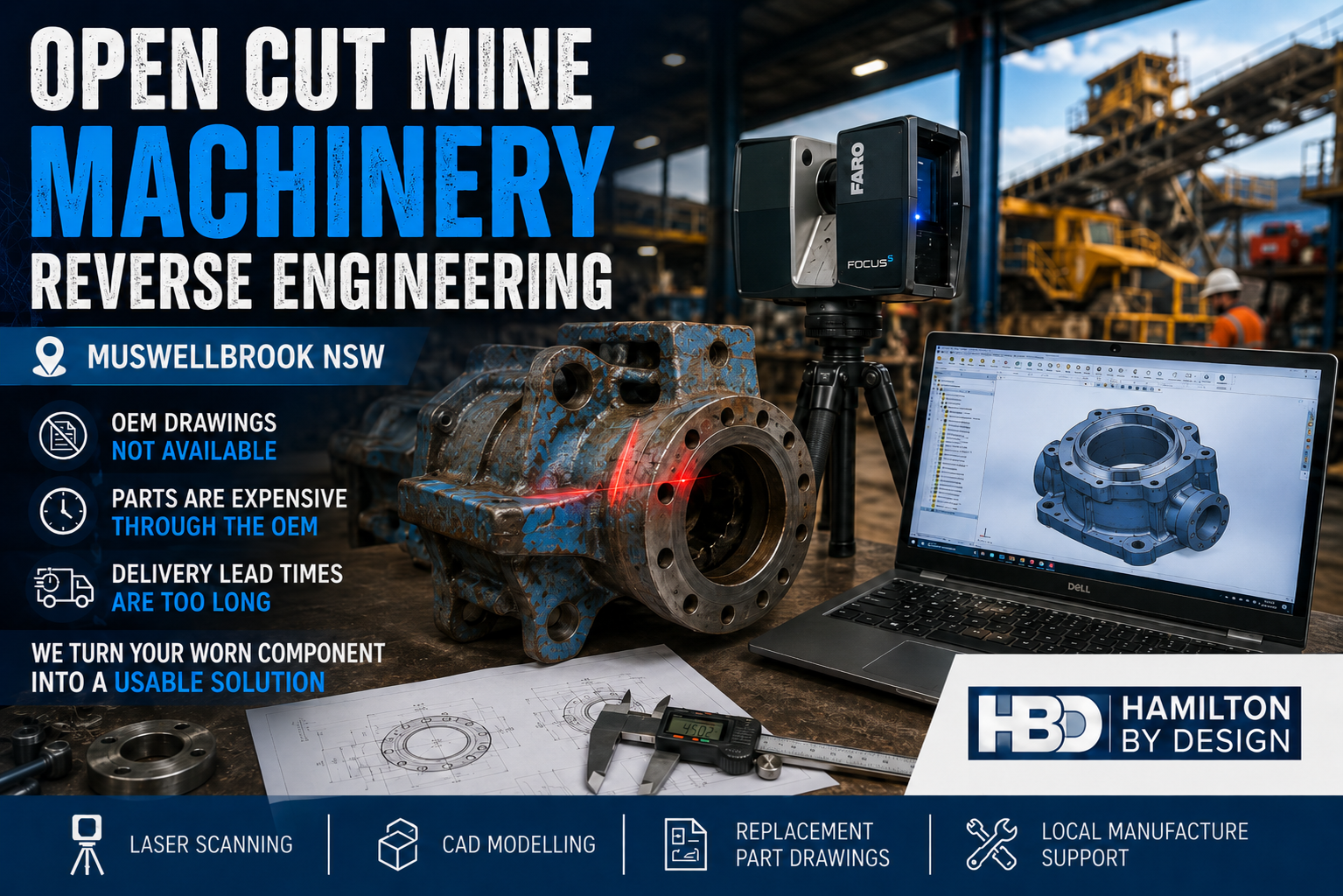
Open cut mine machinery reverse engineering image showing a worn mining component being laser scanned beside a CAD model, with Hamilton By Design branding and Muswellbrook NSW text.

Replacement Parts Without OEM Drawings, Long Lead Times or Excessive OEM Costs

Open cut mining operations around Muswellbrook NSW rely on heavy machinery, fixed plant, conveyors, crushers, feeders, pumps, screens, chutes, hoppers, guards, frames and access systems to keep production moving.

When a critical machinery component wears out, cracks, fails or becomes obsolete, the first option is often to contact the original equipment manufacturer.

But for many mining maintenance teams, that creates a serious problem.

The OEM may not provide detailed drawings.
The replacement part may be expensive.
The delivery lead time may be too long.
The machine may be older, modified or no longer fully supported.

This can leave mine operators, maintenance teams and shutdown planners with limited options when they need a replacement part quickly.

Hamilton By Design supports open cut mining operations, maintenance teams, fabricators and repair workshops with engineering-grade 3D laser scanning and mining plant upgrade support, reverse engineering, CAD modelling and engineering documentation for mine machinery components.

Our focus is not open cut pit scanning or mine survey work. Our focus is machinery, fixed plant, replacement parts and brownfield equipment support.

If a component can be removed, measured, scanned or inspected, it may be possible to develop a 3D CAD model, manufacturing drawing or replacement part design that supports local manufacture, repair or redesign.


The Real Problem: OEM Drawings Are Not Available

For many mining assets, the biggest problem is not always that old site drawings are outdated. The larger problem is that the equipment owner often does not have access to the detailed OEM drawings required to reproduce or repair the part.

The mine may own the machine.

The maintenance team may own the worn component.

The workshop may be able to manufacture a replacement.

But without the correct drawings, dimensions, tolerances, materials and fit-up information, the replacement process becomes difficult.

This is a common problem with:

  • Older mining machinery
  • Imported equipment
  • Obsolete parts
  • Proprietary OEM components
  • Modified equipment
  • Worn mechanical assemblies
  • Shutdown-critical replacement parts
  • Components with long supply lead times
  • Parts that are too expensive through the OEM supply chain

When a part is urgently needed, waiting weeks or months for an imported OEM replacement may not be practical. In some cases, the part cost may also be difficult to justify, especially when a local fabrication or machining solution may be possible.

Reverse engineering provides another pathway.


What Is Mine Machinery Reverse Engineering?

Mine machinery reverse engineering is the process of capturing the geometry, features and function of an existing component so that a usable CAD model, drawing or replacement design can be created.

This may involve laser scanning, manual measurement, inspection, CAD modelling and engineering review.

The aim is to understand the part well enough to support repair, manufacture, fit-up or redesign.

Depending on the component, this may include:

  • Measuring critical diameters
  • Capturing bolt hole patterns
  • Checking shaft, bush and bearing fits
  • Modelling flanges, brackets and housings
  • Recording wear surfaces
  • Capturing complex cast shapes
  • Creating 3D CAD models
  • Producing 2D manufacturing drawings
  • Identifying practical fabrication methods
  • Supporting local machining, fabrication or casting

Reverse engineering is especially useful where the original drawings are not available from the OEM, or where the part has been modified during its service life.

Hamilton By Design also provides replacement part reverse engineering where OEM drawings are unavailable, helping asset owners move from a physical component to usable manufacturing information.


Why This Matters for Muswellbrook Mining Operations

Muswellbrook and the surrounding Upper Hunter region support major mining, industrial maintenance and heavy equipment operations. Open cut mine machinery is exposed to harsh operating conditions, heavy loads, vibration, dust, impact, abrasion and constant production pressure.

When machinery components fail, the issue is rarely simple.

A replacement part may be required urgently.

The part may need to fit into an existing machine.

The equipment may be old or modified.

The OEM may have a long delivery time.

The replacement price may be high.

The mine may need a local repair or manufacturing option.

This is where laser scanning and reverse engineering can assist. Instead of relying only on unavailable OEM drawings, the existing component can be captured, measured and converted into usable engineering information.

That information can then support local manufacturing, repair, redesign or future asset documentation.

For mining operators, contractors and industrial clients across the region, Hamilton By Design provides Hunter Valley mining engineering and 3D laser scanning services focused on practical brownfield plant, machinery and materials handling problems.


Common Machinery Parts That May Be Reverse Engineered

Hamilton By Design can assist with reverse engineering and CAD documentation for a range of mine machinery and fixed plant components.

Examples include:

  • Pump components
  • Bearing housings
  • Drive components
  • Couplings
  • Guards and covers
  • Conveyor components
  • Chute components
  • Hopper parts
  • Wear liners
  • Brackets and mounts
  • Structural frames
  • Shafts and sleeves
  • Flanges and adaptors
  • Fabricated assemblies
  • Cast components
  • Obsolete machine parts
  • Modified equipment parts

Some parts require high-detail measurement. Others require practical engineering judgement to determine which features are critical and which features can be simplified for manufacture.

The goal is not always to create a perfect visual copy of the original part. The goal is to create useful engineering information that allows the replacement part to be manufactured, fitted and used safely.


How Laser Scanning Helps

Laser scanning is useful when a component has complex geometry, difficult-to-measure surfaces or no existing CAD model.

A laser scanner captures the visible surfaces of the part as a point cloud. This data can then be used as a reference for CAD modelling and dimensional checking.

Laser scanning can be especially useful for:

  • Castings
  • Worn parts
  • Complex housings
  • Curved surfaces
  • Irregular shapes
  • Large fabricated items
  • Assemblies with multiple interfaces
  • Parts where manual measurement alone is slow or difficult

However, laser scanning is only one part of the process.

For machinery reverse engineering, critical dimensions still need to be understood. Bearing fits, shaft fits, bolt holes, machined faces, threads, splines, sealing surfaces and alignment features may require additional measurement and engineering review.

That is why Hamilton By Design combines laser scanning with practical mechanical design and CAD modelling experience.


The Reverse Engineering Workflow

A typical reverse engineering workflow may include the following steps.

1. Identify the Part and the Problem

The first step is to understand what the part does and why it needs to be replaced.

Questions may include:

  • Is the part worn, cracked, broken or obsolete?
  • Is the part required for a shutdown?
  • Is the OEM replacement too expensive?
  • Is the lead time too long?
  • Is the part being repaired, copied or improved?
  • Does the replacement need to match the original exactly?
  • Are there known fit-up issues with the existing machine?

Understanding the problem helps determine the correct level of measurement and modelling.

2. Inspect and Measure the Component

The component is inspected and measured. This may include laser scanning, manual measurement, photographs, sketches and notes.

Critical features may include:

  • Bolt hole centres
  • Mounting faces
  • Shaft diameters
  • Bearing locations
  • Overall envelope size
  • Mating faces
  • Wear surfaces
  • Clearance areas
  • Welded or machined details
  • Material thicknesses
  • Assembly interfaces

Where a part is worn, care is needed. The worn shape may not represent the original working geometry. In these cases, engineering judgement may be required to determine the intended size or fit.

3. Create a 3D CAD Model

The measured data is used to create a 3D CAD model.

This model may be developed in SolidWorks, Inventor or another suitable CAD platform. The model can be used to check geometry, confirm fit-up and prepare manufacturing information.

Depending on the job, the model may represent:

  • A single component
  • A machined part
  • A fabricated assembly
  • A casting
  • A guard or cover
  • A chute section
  • A pump component
  • A machine frame
  • A modified replacement design

Hamilton By Design provides 3D CAD modelling for mining, heavy industry and mechanical plant projects, helping convert site measurements, scans, sketches and physical components into practical engineering models.

The model can also be exported in common formats such as STEP, SAT or Parasolid for use by fabricators, machinists or other engineering teams.

4. Produce Manufacturing Drawings

Once the model is complete, 2D drawings can be created for manufacture.

These drawings may include:

  • General dimensions
  • Critical fit dimensions
  • Hole patterns
  • Machined faces
  • Material notes
  • Weld details
  • Fabrication notes
  • Assembly details
  • Tolerance requirements
  • Surface finish requirements where needed

The level of drawing detail should suit the manufacturing process. A fabricated guard does not need the same detail as a machined bearing housing. A cast component may require different information again.

5. Review Fit-Up and Future Use

The replacement part can then be checked against the original component, mating parts or surrounding machine geometry.

Where needed, the CAD data can also be stored for future use. This gives the asset owner better control over future replacement, repair or redesign work.

Once the part has been reverse engineered, the mine is no longer starting from zero the next time that component is required.


Benefits of Reverse Engineering Mine Machinery Parts

Reverse engineering can provide several practical benefits for mine operators, maintenance teams and fabrication workshops.

Reduced Dependence on OEM Drawings

When the OEM will not provide drawings, reverse engineering can create the missing technical information needed to support local manufacture or repair.

Shorter Lead Times

If a local fabricator or machine shop can manufacture the part, the project may avoid long OEM supply delays.

Better Cost Control

OEM replacement parts can be expensive. Reverse engineering can help identify whether local manufacture, repair or redesign is a practical alternative.

Support for Obsolete Equipment

Older machinery may no longer be fully supported. Reverse engineering helps extend the life of useful assets where replacement parts are difficult to obtain.

Improved Shutdown Planning

Having drawings and CAD models ready before a shutdown can reduce uncertainty and improve planning.

Future Asset Control

Once the part is modelled and documented, the mine has better information for future maintenance, procurement and engineering decisions.


Not Every Part Should Be Copied Without Review

Reverse engineering does not mean blindly copying every worn or damaged part.

Some parts are safety critical. Some parts are highly loaded. Some parts may have fatigue, wear, material or heat treatment requirements. Some components may be subject to compliance, certification or OEM warranty considerations.

That means each part should be reviewed properly before manufacture.

In some cases, the best approach may be:

  • Direct replacement
  • Repair
  • Redesign
  • Strength improvement
  • Material upgrade
  • Manufacturing process change
  • Additional engineering verification
  • FEA or stress review
  • Supplier review
  • Third-party certification

Hamilton By Design can assist with the engineering documentation and CAD modelling needed to support these decisions.


Tools Used by Hamilton By Design

Hamilton By Design uses a practical mix of scanning, modelling and engineering tools to support machinery reverse engineering projects.

These may include:

  • FARO Focus laser scanning
  • FARO SCENE point cloud processing
  • Manual measurement and inspection
  • SolidWorks CAD modelling
  • Autodesk Inventor modelling
  • AutoCAD drafting
  • STEP, SAT and Parasolid export
  • 2D manufacturing drawings
  • Assembly drawings
  • Fabrication drawings
  • Design verification
  • SolidWorks Simulation or FEA support where required

The right tools depend on the part, the accuracy required and the manufacturing method.


Why Work With Hamilton By Design?

Hamilton By Design combines site measurement, laser scanning, mechanical design, CAD modelling and practical manufacturing experience.

This is important because mine machinery reverse engineering is not just a scanning exercise.

A scan can capture shape.

But the engineering process must also understand fit, function, manufacturing method, tolerances, material selection, access, assembly and maintenance requirements.

Hamilton By Design can support:

  • Mine operators
  • Maintenance teams
  • Shutdown planners
  • Reliability engineers
  • Fabricators
  • Machine shops
  • Repair workshops
  • Industrial contractors

For Muswellbrook and Upper Hunter mining operations, this service is aimed at machinery and fixed plant problems where the OEM pathway is too slow, too expensive or too restrictive.


Open Cut Mine Machinery Reverse Engineering in Muswellbrook NSW

If your mining operation has a worn, damaged or obsolete machinery component and the OEM will not supply drawings, Hamilton By Design can help create practical engineering information from the existing part.

We can assist with laser scanning, reverse engineering, CAD modelling and manufacturing drawings for mine machinery and fixed plant components.

This can help reduce reliance on OEM supply chains, support local manufacture and improve control over future maintenance.


Hamilton By Design logo displayed on a blue tilted rectangle with a grey gradient background

Need Replacement Part Drawings Without OEM Support?

Hamilton By Design provides reverse engineering and CAD modelling support for mine machinery components in Muswellbrook, the Upper Hunter and across NSW.

If the OEM will not provide drawings, the lead time is too long or the replacement part cost is too high, reverse engineering may provide a practical path forward.

Contact Hamilton By Design to discuss machinery laser scanning, reverse engineering, CAD modelling and replacement part documentation for mining equipment and fixed plant components.

Talk to Us – Contact Us

Name
Would you like us to arrange a phone consultation for you?
Address

Our clients:


https://www.hamiltonbydesign.com.au/scan-to-bim-services-australia-lidar-point-clouds-cad-modelling

Surface Mine 3D LiDAR Scanning for Hunter Valley, Singleton, Muswellbrook & Upper Hunter NSW

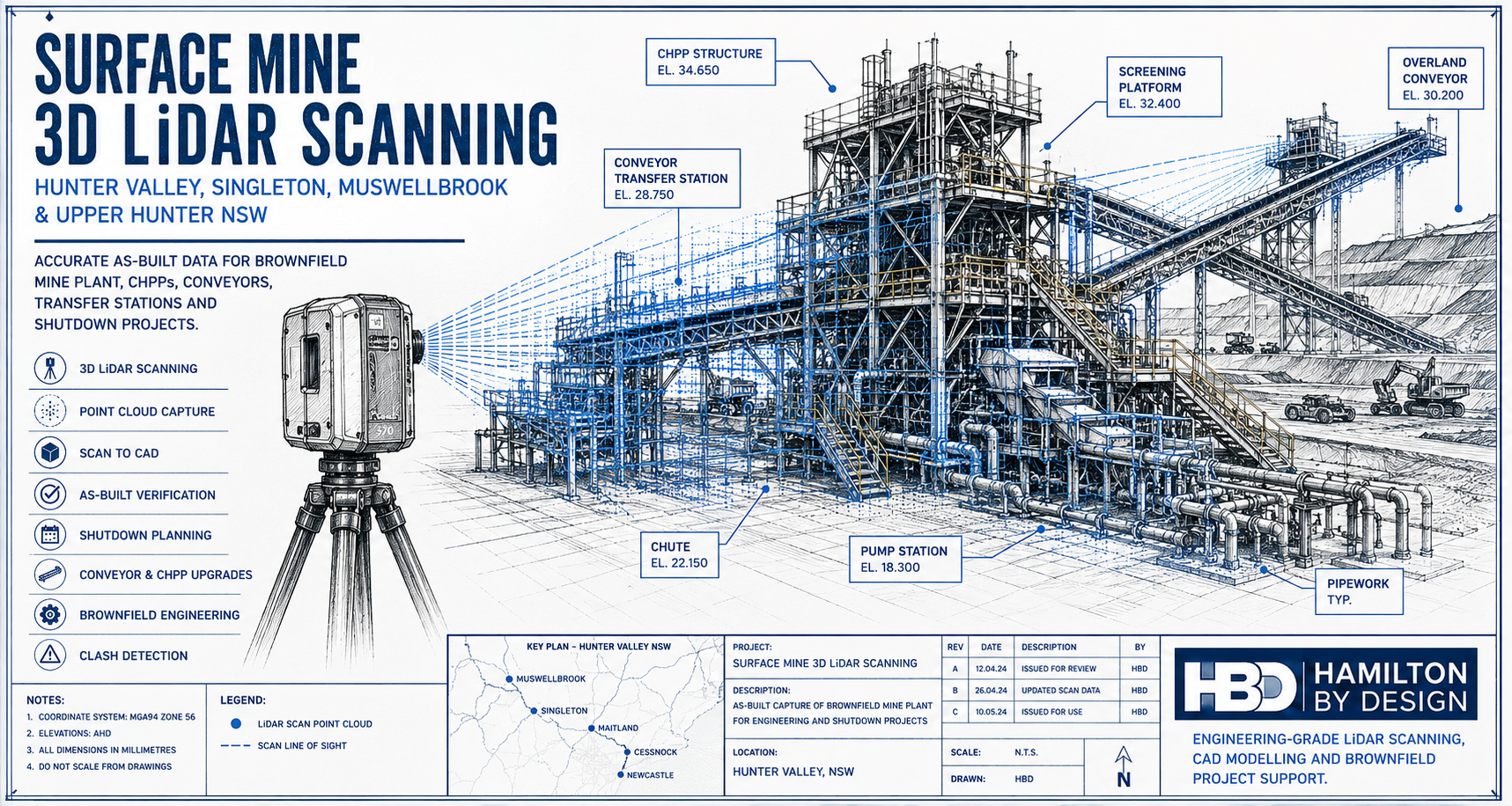
Technical drawing style hero image showing a 3D LiDAR scanner capturing a Hunter Valley surface mine processing plant with conveyors, CHPP structure, pipework, pump station and brownfield mining infrastructure.

Surface Mine 3D LiDAR Scanning for Brownfield Mine Sites

Blue 3D LiDAR scanner icon on a tripod with scanning waves

Surface mines across the Hunter Valley and Upper Hunter are constantly changing. Coal handling plants, conveyors, transfer stations, pump stations, workshops, access platforms, pipework, chutes, bins and rail load-out areas are regularly modified to keep production moving. Some changes are part of planned capital upgrades. Others happen during shutdowns, maintenance windows or urgent repair work.

After years of brownfield modifications, the problem becomes simple: the plant on site no longer matches the drawings.

For surface mine operators, outdated drawings create real engineering and shutdown risk. Engineers may design around old information. Fabricators may manufacture parts that do not fit. Shutdown planners may miss access restrictions, clashes or tie-in issues. Installation crews may arrive on site only to discover that pipework, steelwork, guards, walkways or equipment are not where the drawings say they are.

This is where 3D laser scanning provides real value. By capturing accurate existing-condition data of the installed plant, mine operators and engineering teams can make decisions based on what is actually on site, not what was originally drawn years ago.

Hamilton By Design provides engineering-grade 3D LiDAR scanning, point cloud processing, scan-to-CAD modelling and as-built verification for Hunter Valley surface mines and brownfield industrial sites.

Locations Supported Across the Hunter Valley and Upper Hunter

Hamilton By Design supports surface mine and heavy industrial projects across the Hunter Valley, Upper Hunter and surrounding mining support regions, including:

Singleton, Muswellbrook, Ravensworth, Lemington, Warkworth, Mount Thorley, Broke, Bulga, Camberwell, Hebden, Jerrys Plains, Rixs Creek, Glennies Creek, Maison Dieu, Whittingham, Liddell, Bayswater, Aberdeen, Denman, Scone, Maitland, Cessnock, Lake Macquarie, Newcastle and the Port of Newcastle corridor.

These locations are affected by the same brownfield engineering problem. Mine plant is modified over time, but the drawing register does not always keep up. A conveyor transfer station may have extra guarding. A pump station may have replacement pipework. A CHPP may have modified chutes, platforms, cable trays and access stairs. A rail load-out area may have structural or mechanical changes that are not fully documented.

Hamilton By Design also supports industrial and mining clients beyond the Hunter Valley through 3D laser scanning across Australia, helping project teams capture reliable as-built data for plant upgrades, shutdown planning, fabrication checks and engineering verification.

Why Existing Surface Mine Drawings Become Outdated

Surface mine infrastructure rarely stays the same for long. Production requirements change. Maintenance teams improve access. Process engineers adjust layouts. Shutdown crews replace equipment. Fabricators install revised steelwork. Emergency repairs become permanent. Over time, these small changes create a large difference between the original drawings and the actual plant.

Common causes of outdated drawings include:

Brownfield ChangeResulting Risk
Conveyor upgradesNew chutes, guards or drives may not match old layouts
CHPP modificationsPipework, platforms and equipment positions may change
Pump station changesFlanges, valves and pipe supports may not be in the documented location
Structural access upgradesStairs, ladders, handrails and platforms may have been added or replaced
Shutdown repairsTemporary supports or modifications may become permanent
Replacement equipmentNew motors, pumps, screens or gearboxes may have different footprints
Rail load-out changesStructural and mechanical interfaces may no longer match original drawings
Site services modificationsCable trays, water lines, air lines and drainage may be undocumented

When drawings are unreliable, engineering design becomes slower and riskier. More time is spent checking dimensions, confirming interfaces and resolving clashes. In a shutdown environment, that uncertainty can become expensive very quickly.

What 3D LiDAR Scanning Captures

3D LiDAR scanning captures the existing mine plant as a measured 3D point cloud. The scanner records millions of points from multiple positions, creating a detailed digital record of the installed site condition.

For surface mining projects, LiDAR scanning can capture:

  • Conveyor transfer stations
  • CHPP areas
  • Crusher stations
  • Screens and bins
  • Chutes and hoppers
  • Pump stations
  • Pipework and valve stations
  • Structural steelwork
  • Platforms, stairs, ladders and handrails
  • Workshops and maintenance bays
  • Rail load-out structures
  • Stockpile conveyor systems
  • Water management infrastructure
  • Electrical rooms and cable tray support areas
  • Brownfield tie-in zones

The point cloud can then be used for engineering review, CAD modelling, clash detection, as-built documentation, shutdown planning and fabrication support.

Turning Scan Data into Engineering Information

The scan is only the first step. The real value comes from turning point cloud data into information engineers, fabricators and project teams can use.

Hamilton By Design can convert captured site data into 3D CAD modelling outputs suitable for mechanical layouts, plant upgrades, fabrication planning, clash checking and as-built documentation.

For example, if a mine is planning to replace a chute, the scan can capture the surrounding steelwork, conveyor geometry, access platforms, guards and nearby equipment. The design team can then model the new chute around the actual site conditions. This reduces the chance of a clash during installation.

If a pump station is being modified, LiDAR scanning can confirm the true location of pipework, flanges, valves, supports and access clearances. This helps fabricators produce more accurate spools and reduces the need for site rework.

If a CHPP area has been modified many times, scanning can provide an updated as-built record that engineers can use for future upgrades.

For shutdown projects, the value is even greater. Shutdown windows are limited. Mistakes are costly. If parts do not fit, access is blocked or tie-in points are wrong, the project can lose valuable time. 3D LiDAR scanning helps reduce those unknowns before the shutdown begins.

Typical Deliverables

Hamilton By Design can support surface mine scanning projects with practical engineering deliverables, including:

DeliverablePurpose
Registered point cloudAccurate 3D record of the existing plant
E57 / RCP / RCS / LAS filesPoint cloud formats for CAD and review workflows
3D CAD modelEngineering model of selected plant, equipment or structure
2D GA drawingsPlans, elevations and sections for design and review
Scan-to-CAD modelConverts point cloud data into usable CAD geometry
Clash reviewChecks proposed equipment against existing site conditions
Tie-in verificationConfirms exact positions before fabrication
Shutdown work pack supportHelps planners, engineers and installers understand the site
As-built documentationUpdates records after years of brownfield change

The deliverable should match the engineering problem. Some projects only need a point cloud. Others need a detailed CAD model, fabrication drawings or clash detection review.

Example Project Applications

Surface mine 3D LiDAR scanning is useful for many common Hunter Valley mining projects, including:

  • Conveyor transfer station upgrades
  • Chute replacement and redesign
  • CHPP brownfield modifications
  • Pump station upgrades
  • Pipework replacement and spool verification
  • Access platform and stair upgrades
  • Structural steel verification
  • Crusher and screen area modifications
  • Rail load-out upgrades
  • Workshop and maintenance bay layout changes
  • Shutdown planning and installation checks
  • Reverse engineering of obsolete components
  • As-built documentation for undocumented plant

For worn, modified or undocumented mining equipment, Hamilton By Design can also support reverse engineering for mining and industrial equipment. This is useful where existing parts, structures or assemblies need to be captured, modelled and converted into practical engineering documentation.

Why Use an Engineering-Led Scanning Approach?

Not all scanning is the same. For surface mine projects, the scan needs to support engineering decisions. That means the scanner operator must understand what matters to the design team: tie-in points, access clearances, structural interfaces, equipment footprints, maintenance envelopes, lifting paths and shutdown constraints.

An engineering-led scanning approach focuses on the areas that affect design, fabrication and installation. It is not just about capturing a large point cloud. It is about capturing the right information so the project team can reduce risk.

Hamilton By Design combines 3D LiDAR scanning with mechanical engineering, CAD modelling, drafting and brownfield project experience. This allows the scan data to be turned into practical engineering outputs that support real site work.

Hamilton By Design logo displayed on a blue tilted rectangle with a grey gradient background

Conclusion

Surface mines across the Hunter Valley, Singleton, Muswellbrook and Upper Hunter region often operate with plant that has changed significantly over many years. Drawings may be incomplete, outdated or inconsistent with what is installed on site.

For brownfield mining projects, this creates risk. New equipment can clash with existing plant. Fabricated parts may not fit. Shutdown work can be delayed. Engineering teams may spend too much time checking dimensions manually.

Surface Mine 3D LiDAR Scanning helps solve this problem by capturing accurate as-built data of the existing plant. The point cloud can then be used for CAD modelling, clash checking, shutdown planning, fabrication support and engineering verification.

For Hunter Valley surface mine operators, the message is clear:

If the drawings are no longer reliable, scan the plant before designing, fabricating or installing the next modification.

Talk to Us – Contact Us

Name
Would you like us to arrange a phone consultation for you?
Address

Our clients:


https://www.hamiltonbydesign.com.au/scan-to-bim-services-australia-lidar-point-clouds-cad-modelling

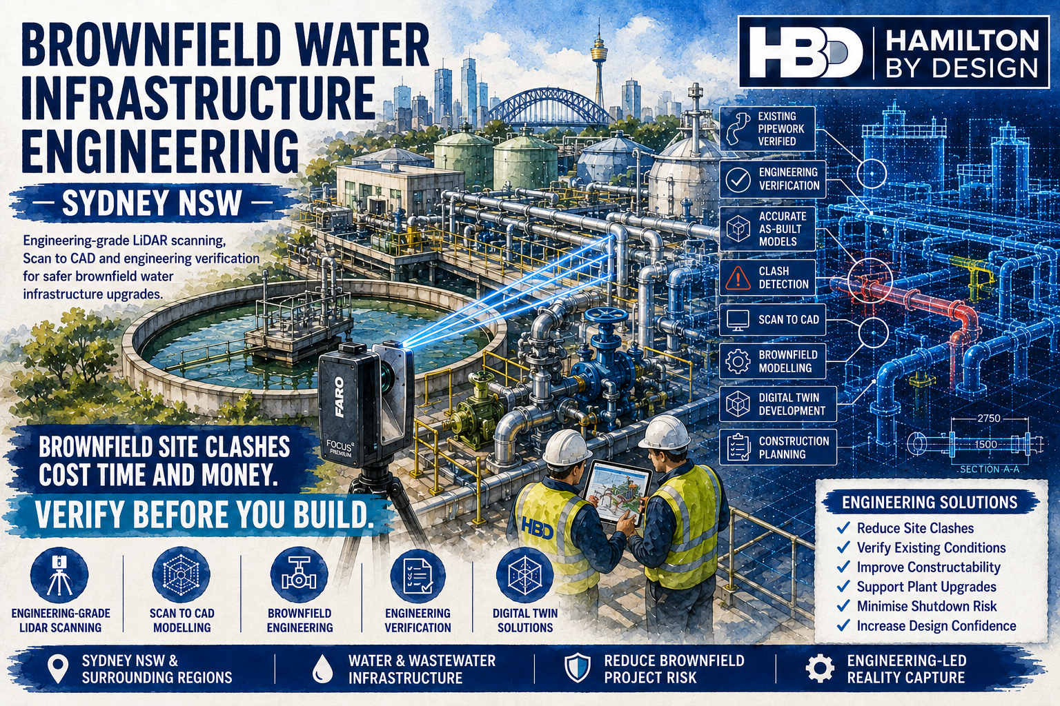
Brownfield Water Infrastructure Engineering in Sydney NSW โ€“ Reduce Risk Before Construction Begins

Engineering-grade LiDAR scanning of Sydney brownfield water infrastructure, capturing existing pipework, tanks, pumps and structural assets to support engineering verification, Scan to CAD and digital twin development.

Sydney’s water infrastructure is constantly evolving. Ageing water treatment plants, wastewater treatment facilities, pumping stations, reservoirs and transfer pipelines require ongoing upgrades to meet increasing demand, improve reliability and comply with changing environmental regulations.

Unlike greenfield projects where engineers begin with an empty site, brownfield projects involve modifying existing operational infrastructure. Every new pipe, pump, platform or structural support must integrate seamlessly with equipment that may have been installed decades ago.

The greatest challenge with brownfield engineering is simple:

Existing infrastructure rarely matches the available drawings.

Over many years, maintenance activities, emergency repairs, plant expansions and operational improvements alter facilities in ways that are often never fully documented. As a result, engineering teams frequently encounter unknown pipework, relocated equipment, modified structural steel and outdated as-built drawings.

These discrepancies create one of the biggest risks in industrial engineering:

Brownfield modifications causing costly site clashes.

Hamilton By Design provides Brownfield Water Infrastructure Engineering Services throughout Sydney NSW, combining engineering-grade LiDAR scanning, Scan to CAD, mechanical engineering and engineering verification to reduce project risk before construction begins.


Why Brownfield Projects Are More Complex Than Greenfield Projects

A greenfield project starts with a clean site.

Engineers control every dimension, every structural member and every equipment location.

Brownfield projects are completely different.

Existing facilities already contain:

  • Operating equipment
  • Underground services
  • Congested pipework
  • Electrical infrastructure
  • Instrumentation
  • Structural steel
  • Maintenance platforms
  • Access walkways
  • Cable trays
  • Temporary modifications
  • Legacy equipment

Every new design must fit around existing infrastructure while maintaining safe operation.

That is why accurate existing-condition data is essential.


The Hidden Cost of Site Clashes

A site clash occurs when newly designed equipment conflicts with existing infrastructure.

Typical clashes include:

  • Pipework intersecting structural steel
  • Pumps fouling maintenance platforms
  • Valves becoming inaccessible
  • Cable trays blocking pipe routing
  • Pipe supports interfering with existing equipment
  • Motors conflicting with overhead beams
  • Access ladders blocking maintenance paths
  • Concrete foundations overlapping underground services

Many of these issues are only discovered during construction.

By that stage:

  • fabrication is complete
  • contractors are mobilised
  • shutdowns have commenced
  • installation crews are waiting

The result is expensive redesign, fabrication changes and extended project durations.


Engineering-Grade LiDAR Scanning Eliminates Guesswork

Hamilton By Design uses professional terrestrial LiDAR scanning to accurately capture existing water infrastructure.

Rather than relying on tape measures or outdated drawings, millions of survey points are recorded across the entire facility.

This captures:

  • Pumps
  • Pipework
  • Valves
  • Tanks
  • Structural steel
  • Pipe bridges
  • Clarifiers
  • Digesters
  • Access platforms
  • Stairways
  • Handrails
  • Electrical equipment
  • Cable trays
  • Instrumentation
  • Concrete structures

The resulting point cloud becomes the single source of truth for engineering design.


Accurate Existing Conditions Lead to Better Engineering

Reliable engineering begins with reliable information.

Accurate point cloud data enables engineers to:

  • Verify dimensions
  • Confirm pipe routing
  • Check equipment locations
  • Validate maintenance access
  • Measure structural geometry
  • Review installation clearances
  • Detect clashes before construction
  • Plan shutdown activities

Instead of making assumptions, engineers work from the actual plant.


Supporting Water Infrastructure Projects Across Sydney

Hamilton By Design supports a wide range of brownfield water infrastructure projects.

These include:

Water Treatment Plant Upgrades

Treatment plants require continual investment to maintain water quality and increase capacity.

LiDAR scanning provides accurate existing-condition data before detailed engineering begins.


Wastewater Treatment Plant Modifications

Wastewater facilities often involve highly congested process pipework.

Accurate point clouds reduce installation risk during process upgrades.


Pump Station Engineering

Pump replacements frequently require:

  • new baseplates
  • pipework modifications
  • motor upgrades
  • structural changes

Scanning ensures replacement equipment integrates correctly.


Reservoir Infrastructure

Reservoir facilities require accurate engineering for:

  • inlet pipework
  • outlet manifolds
  • valve chambers
  • overflow systems
  • maintenance platforms

Reality capture improves design certainty.


Transfer Pipeline Connections

Tie-ins to existing pipelines require precise dimensional verification.

LiDAR scanning allows engineers to accurately model connection points before fabrication.


Scan to CAD Services

Point clouds are valuable, but engineering projects generally require CAD models.

Hamilton By Design converts point cloud data into:

  • Intelligent 3D models
  • General Arrangement drawings
  • Pipework models
  • Structural steel models
  • Equipment layouts
  • Sections
  • Elevations
  • Fabrication drawings
  • As-built documentation

These deliverables integrate with:

  • SOLIDWORKS
  • Autodesk Inventor
  • AutoCAD
  • Navisworks
  • Autodesk ReCap

Engineering Verification Before Construction

Engineering verification is one of the most valuable outcomes of reality capture.

Before fabrication begins, proposed designs can be compared against existing infrastructure.

Verification includes:

  • Equipment fit
  • Pipe routing
  • Structural interfaces
  • Maintenance access
  • Installation clearances
  • Lifting paths
  • Serviceability
  • Constructability

Resolving these issues during design significantly reduces project risk.


Supporting Digital Twin Development

Many Sydney water authorities are developing digital twins to improve long-term asset management.

LiDAR scanning provides the accurate geometric foundation required for these systems.

Digital twins assist with:

  • Asset management
  • Maintenance planning
  • Shutdown coordination
  • Future upgrades
  • Operator training
  • Lifecycle management
  • Engineering studies
  • Capital planning

Because the model reflects actual site conditions, future projects begin with reliable information.


Reducing Shutdown Risk

Brownfield water infrastructure projects often occur during tightly controlled shutdowns.

Unexpected site clashes can quickly extend shutdown durations.

LiDAR scanning helps engineers:

  • Detect clashes early
  • Validate fabrication
  • Optimise installation sequences
  • Improve access planning
  • Confirm equipment clearances

Many construction problems are therefore resolved before anyone arrives on site.


Typical Brownfield Engineering Workflow

Hamilton By Design follows an engineering-led workflow designed specifically for operational infrastructure.

1. Project Definition

Understand project objectives, operational constraints and shutdown requirements.

2. Engineering LiDAR Scanning

Capture existing infrastructure using terrestrial laser scanning.

3. Point Cloud Registration

Register scans into one accurate engineering dataset.

4. Quality Assurance

Verify scan completeness and registration accuracy.

5. Scan to CAD

Develop engineering-ready models from the point cloud.

6. Engineering Design

Complete mechanical, structural and pipework design using verified site information.

7. Engineering Verification

Compare proposed modifications against existing infrastructure before fabrication.

8. Construction Support

Provide engineering assistance during installation if required.


Why Choose Hamilton By Design?

Hamilton By Design combines practical engineering knowledge with advanced reality capture technology.

Our capabilities include:

  • Engineering-grade LiDAR scanning
  • Brownfield engineering support
  • Mechanical engineering
  • Reverse engineering
  • Scan to CAD
  • Engineering drafting
  • Structural modelling
  • Pipework modelling
  • As-built documentation
  • Digital twin development
  • Engineering verification
  • Construction support

Unlike traditional survey-only providers, we understand how engineering models will be used throughout the project lifecycle.

Our reality capture services are designed to produce information engineers can immediately use for design, verification and construction planning.


Supporting Sydney’s Essential Water Infrastructure

Sydney’s water infrastructure supports millions of residents, businesses and industries every day. As assets continue to age, brownfield engineering projects will become increasingly important to maintain reliable services and improve operational performance.

Successful brownfield engineering depends on one critical factor:

Accurate existing-condition information.

Without reliable data, unknown infrastructure creates unnecessary engineering risk, costly site clashes and expensive construction delays.

Hamilton By Design provides engineering-grade LiDAR scanning, Scan to CAD modelling and engineering verification services that replace uncertainty with confidence. By accurately capturing existing water infrastructure before design begins, we help engineering consultants, utilities and contractors reduce project risk, improve constructability and deliver successful brownfield upgrades.

Whether your project involves a water treatment plant, wastewater treatment facility, pumping station, reservoir or pipeline connection, our engineering-led approach ensures every design decision is based on the facility as it exists todayโ€”not outdated drawings or assumptions.

Talk to Us – Contact Us

Name
Would you like us to arrange a phone consultation for you?
Address

Our clients:
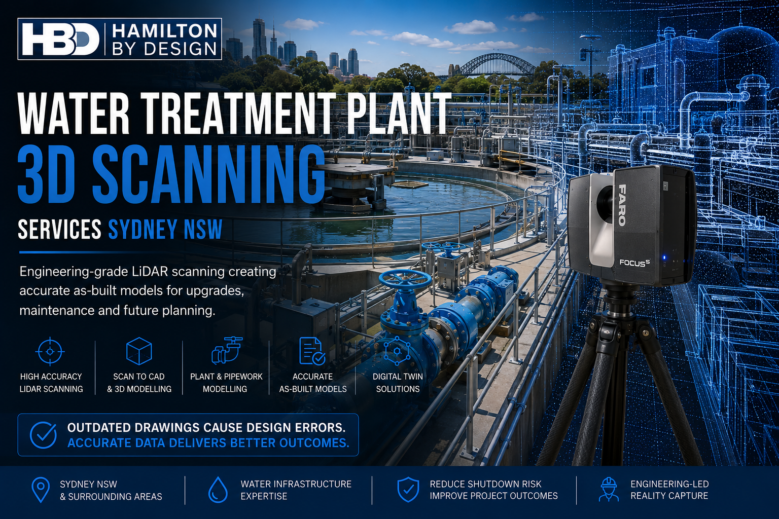


Water Treatment Plant 3D Scanning Services in Sydney NSW โ€“ Accurate As-Built Data for Smarter Engineering

Engineering-grade LiDAR scanning at a Sydney water treatment plant, capturing tanks, pipework and process infrastructure to create accurate As-Built models for plant upgrades, Scan to CAD and digital twin development.

Water treatment plants are among Australia’s most critical infrastructure assets. They operate continuously to deliver safe, reliable drinking water to millions of people while meeting stringent regulatory and environmental requirements. As Sydney continues to invest in expanding and modernising its water infrastructure, engineering teams are increasingly faced with a common challenge:

The existing as-built drawings no longer reflect what is actually installed on site.

Over decades of operation, treatment plants undergo numerous modifications. Pumps are replaced, pipework is rerouted, valves are upgraded, electrical equipment is relocated, and structural steel is modified to suit operational requirements. Unfortunately, these changes are not always captured in the engineering documentation.

When engineers begin designing upgrades using outdated drawings, errors quickly emerge. Pipework clashes with existing infrastructure, replacement equipment fails to fit, structural supports require redesign, and shutdown schedules are extended while unexpected site modifications are completed.

Hamilton By Design provides engineering-grade Water Treatment Plant 3D Scanning Services throughout Sydney NSW, using terrestrial LiDAR scanning to create highly accurate digital representations of existing facilities. By replacing outdated drawings with reliable reality capture, engineering teams can design with confidence, reduce project risk and improve construction outcomes.


The Problem with Outdated As-Built Drawings

Many of Sydney’s water treatment facilities have been operating for several decades. During this time, numerous maintenance activities and capital upgrades have altered the original plant configuration.

Typical undocumented changes include:

  • Replacement pumps with different footprints
  • Pipework rerouted around new equipment
  • Additional valves and instrumentation
  • Modified pipe supports
  • Structural strengthening
  • New cable trays
  • Electrical switchboard upgrades
  • Temporary modifications that became permanent
  • Altered maintenance platforms
  • Relocated access ladders

Although each modification may have been appropriate at the time, the cumulative effect is that original drawings often no longer represent actual site conditions.

Engineering projects based on these outdated documents carry significant risk.


Why Accurate Existing Conditions Matter

Every brownfield engineering project begins with one critical question:

What is actually installed today?

Without accurate existing information, designers are forced to rely on assumptions or undertake extensive manual site measurements.

Both approaches introduce unnecessary risk.

Common design issues include:

  • Pipework that does not align during installation
  • Pump discharge flanges requiring on-site modification
  • Structural steel interfering with new equipment
  • Insufficient maintenance access
  • Cable trays clashing with pipe supports
  • Valve actuators becoming inaccessible
  • Equipment foundations requiring redesign
  • Lifting clearances being overlooked

These problems typically become apparent during construction, when the cost of correcting them is significantly higher.


Engineering LiDAR Scanning Removes Uncertainty

Hamilton By Design uses professional terrestrial LiDAR scanners to capture millions of highly accurate measurement points throughout a water treatment facility.

Rather than recording selected dimensions using conventional survey methods, laser scanning captures the complete geometry of the plant.

Typical assets captured include:

  • Process pipework
  • Pumps
  • Motors
  • Valves
  • Tanks
  • Clarifiers
  • Filters
  • Chemical dosing systems
  • Structural steel
  • Pipe bridges
  • Walkways
  • Stairways
  • Handrails
  • Electrical switchrooms
  • MCC rooms
  • Cable trays
  • Instrumentation
  • Concrete structures

The result is a comprehensive point cloud representing the true existing condition of the facility.

Engineers can measure any feature directly from the scan throughout the design process without repeatedly returning to site.


Supporting Water Treatment Plant Upgrades

Sydney’s treatment plants require continual investment to maintain reliability, increase capacity and improve operational efficiency.

LiDAR scanning supports projects such as:

Pump Replacements

Replacement pumps frequently differ from the original equipment.

Accurate scanning ensures:

  • baseplates align correctly
  • suction and discharge pipework matches
  • maintenance clearances are maintained
  • lifting access is preserved

Pipework Modifications

Process improvements often require:

  • larger diameter pipework
  • bypass systems
  • additional isolation valves
  • flow meters
  • chemical dosing lines

Accurate point clouds allow new spool pieces to be designed around existing infrastructure before fabrication begins.


Structural Modifications

New equipment installations commonly require:

  • equipment platforms
  • maintenance walkways
  • lifting beams
  • pipe supports
  • access ladders
  • handrails

Scanning captures every structural member to ensure new steel integrates correctly.


Electrical and Instrumentation Upgrades

Electrical upgrades benefit significantly from reality capture.

Designers can accurately model:

  • cable trays
  • conduits
  • MCC rooms
  • switchboards
  • instrument locations
  • communication systems

This improves installation planning while reducing field modifications.


Creating Accurate As-Built Models

One of the greatest advantages of engineering-grade LiDAR scanning is the ability to create reliable as-built models.

These models provide:

  • current equipment locations
  • verified pipe routing
  • structural layouts
  • equipment dimensions
  • maintenance clearances
  • plant configuration

Unlike historic drawings, as-built models reflect the facility exactly as it exists today.

They become the foundation for future engineering projects.


Scan to CAD for Engineering Design

Point clouds are extremely valuable, but engineering projects often require intelligent CAD models.

Hamilton By Design converts point cloud data into engineering deliverables including:

  • 3D CAD models
  • General Arrangement drawings
  • Equipment layouts
  • Pipe routing models
  • Structural steel models
  • Plant sections
  • Elevations
  • Fabrication drawings
  • As-built documentation

These models integrate directly into engineering workflows using software such as Autodesk, SOLIDWORKS and Navisworks.


Supporting Digital Twin Development

Many water authorities are now investing in digital twins to improve long-term asset management.

LiDAR scanning forms the foundation of these digital assets.

A digital twin can support:

  • maintenance planning
  • shutdown coordination
  • asset lifecycle management
  • operator training
  • future upgrades
  • capital works planning
  • condition assessments
  • engineering analysis

Rather than relying on outdated information, the digital twin represents actual plant conditions.


Reducing Shutdown Risk

Water treatment plants often operate continuously, making shutdown planning critical.

Unexpected design errors during shutdowns can result in:

  • extended outages
  • contractor delays
  • increased labour costs
  • emergency fabrication
  • delayed commissioning

Accurate 3D scanning identifies potential issues before work begins.

Engineers can perform visual clash detection, verify clearances and optimise installation sequences during the design stage.

This significantly reduces project risk.


Brownfield Engineering Expertise

Unlike greenfield facilities, brownfield projects require engineers to work around existing assets.

Hamilton By Design specialises in engineering support for brownfield infrastructure, including:

  • water treatment plants
  • wastewater treatment plants
  • pumping stations
  • reservoirs
  • chemical dosing facilities
  • filtration plants
  • process buildings

Engineering-grade reality capture provides confidence that new infrastructure will integrate successfully with existing operations.


Typical Project Workflow

Our engineering workflow has been developed specifically for operational infrastructure.

1. Project Planning

Review plant access requirements, shutdown windows and engineering objectives.

2. Site LiDAR Scanning

Capture complete facility geometry using terrestrial laser scanning.

3. Scan Registration

Combine individual scans into one accurate point cloud.

4. Quality Assurance

Verify registration accuracy and confirm complete site coverage.

5. Engineering Modelling

Develop CAD models, equipment layouts and engineering documentation.

6. Design Integration

Use accurate as-built information to complete mechanical, structural and process designs.

7. Construction Verification

Verify proposed upgrades against existing infrastructure before fabrication.


Why Choose Hamilton By Design?

Hamilton By Design provides more than laser scanning.

We combine engineering expertise with advanced reality capture technologies to deliver practical engineering solutions.

Our capabilities include:

  • Engineering-grade terrestrial LiDAR scanning
  • Mechanical engineering design
  • Scan to CAD services
  • Reverse engineering
  • Pipework modelling
  • Structural steel modelling
  • Engineering drafting
  • Digital twin development
  • As-built verification
  • Brownfield engineering support
  • Shutdown engineering planning

Because our engineers understand industrial facilities, we capture the information that designers actually needโ€”not just visually impressive point clouds.


Supporting Sydney’s Water Infrastructure

Sydney’s water treatment plants play a vital role in supplying safe drinking water to millions of residents and businesses. As these facilities continue to expand, modernise and replace ageing assets, engineering accuracy becomes increasingly important.

Outdated as-built drawings should never be the reason a project experiences delays, redesigns or costly construction changes.

Engineering-grade LiDAR scanning provides reliable existing-condition data that supports smarter engineering decisions, reduces construction risk and improves project outcomes.

Whether your project involves replacing pumps, modifying pipework, upgrading process equipment or creating a digital twin, Hamilton By Design delivers accurate 3D scanning, engineering modelling and Scan to CAD services throughout Sydney NSW.

By capturing the plant exactly as it exists today, we help ensure tomorrow’s upgrades fit correctly the first time.

Talk to Us – Contact Us

Name
Would you like us to arrange a phone consultation for you?
Address

Our clients:


https://www.hamiltonbydesign.com.au/scan-to-bim-services-australia-lidar-point-clouds-cad-modelling























