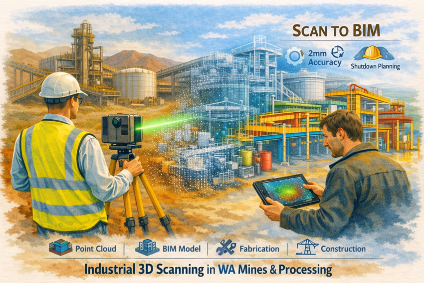
Industrial 3D Scanning in WA Mines & Processing | Scan-to-BIM
Building Engineering Certainty in Brownfield Environments
Western Australia’s mining and mineral processing sector operates some of the most complex industrial assets in the world. Aging infrastructure, continuous production demands, and aggressive expansion schedules mean that every engineering decision must be based on accurate, reliable information. Industrial 3D Scanning in WA Mines & Processing has become the foundation for achieving this certainty—providing precise digital representations of plants, structures, and equipment before a single drawing is issued.
The Backbone of Modern Mine Engineering
A laser scan is not simply a survey tool; it is the backbone of the entire project lifecycle. The quality of the initial scan determines the ease and accuracy of every task that follows—layout design, clash detection, fabrication, and construction. If the backbone is broken, even simple tasks become difficult. Poor capture leads to rework, fabrication errors, and costly shutdown delays.
Industrial 3D scanning captures millions of measured points across conveyors, tanks, structural steel, pipe racks, and mechanical equipment with millimetre accuracy. For WA mine sites where access is restricted and downtime is expensive, this technology removes guesswork and replaces assumptions with verified data.
The true value of scanning lies in what is delivered after capture. For mines and processing facilities, typical outputs include:
Engineering-grade point clouds for AutoCAD, Revit, and plant design platforms
Scan-to-BIM models of structures, pipework, and mechanical systems
Fabrication-ready DXF, STEP, or Parasolid files
Navisworks meshes for stakeholder review and constructability planning
As-built verification for shutdown and tie-in works
These deliverables allow engineering teams to design remotely, plan upgrades with confidence, and eliminate the need for repeated site visits across the vast distances of Western Australia.
Protecting the Project Team
Industrial projects are often pressured by schedules and budgets. High-quality 3D scanning protects the entire delivery team—project managers, engineers, designers, and fabricators—by providing an objective source of truth. When design decisions are based on measured reality rather than tape measures and sketches, disputes reduce and collaboration improves.
For brownfield WA sites with decades of undocumented modifications, scanning becomes the neutral reference that aligns contractors, owners, and operators around the same dataset.
Applications Across WA Mines & Processing
Industrial 3D Scanning in WA Mines & Processing supports a wide range of activities:
Shutdown planning and tie-in verification
Conveyor and chute upgrades
Tank and structural remediation
Pipe spool prefabrication
Access platform and maintenance improvements
Expansion of crushing and screening circuits
Safety and egress compliance reviews
Whether in the Pilbara iron ore operations, Goldfields processing plants, or nickel and lithium facilities, scanning reduces risk in some of Australia’s harshest and most remote environments.
Remote Doesn’t Mean Isolated
Western Australian mine sites can feel isolated, yet digital capture connects them directly to engineering teams anywhere in Australia. A single field visit can provide enough data for months of detailed design work. Teams can “walk the plant” virtually, measure clearances, and develop solutions without repeated flights or shutdown interruptions.
An Engineer-Led Approach
Effective scan programs must be led by engineers who understand how the data will be used. Capture strategies, target placement, and accuracy tolerances are defined around the BIM deliverables, not around the scanner. This ensures that the final models support fabrication, not just visualisation.
Industrial 3D Scanning in WA Mines & Processing is no longer optional—it is the starting point for safe, efficient, and predictable project delivery. When the backbone is strong, every downstream task becomes easier.
If your operation is planning upgrades, shutdowns, or expansions, begin with a measured digital foundation and let the data drive the outcome.
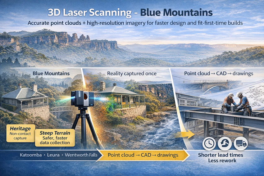
The Blue Mountains presents some of the most demanding environments for measurement and design in NSW. Steep escarpments, ageing heritage buildings, bushfire-affected properties, and complex tourism infrastructure mean that traditional survey methods are often unsafe, incomplete, or inaccurate.
Hamilton By Design provides engineering-grade 3D laser scanning across the Blue Mountains — delivering precise point clouds and high-resolution imagery that can be used directly for structural design, drafting, approvals, and construction.
Engineering Data You Can Design From
Our workflow is built around the FARO Focus LiDAR platform, capturing millions of points with millimetre accuracy. Unlike basic reality capture, our service is aimed specifically at engineering and fabrication outcomes:
Point clouds aligned to project coordinate systems
Accuracy suitable for structural steel interfaces
High-resolution HDR imagery from the scanner camera
Data prepared for SolidWorks, AutoCAD and BIM workflows
Outputs ready for drafting and clash detection
This is not marketing visualisation — it is measurement data that engineers can rely on.
Why the Blue Mountains Demands Professional Scanning
Projects in Katoomba, Leura, Wentworth Falls and Springwood share common risks:
Original drawings rarely match existing conditions
Buildings sit on rock shelves and irregular terrain
Access is limited and weather changes quickly
Heritage fabric must not be touched
Bushfire rebuilds require objective records
In these environments, even small measurement errors lead to major problems during fabrication and installation. Engineering-grade scanning removes that uncertainty by capturing reality first.
What We Scan in the Blue Mountains
Structural & Industrial
Platforms and access structures
Steel upgrades and extensions
Mechanical plant rooms
Conveyor and process equipment
Bridges and rail infrastructure
Heritage & Tourism
Federation cottages and guesthouses
Scenic World structures
Lookouts and stone pathways
Churches and community buildings
Residential & Bushfire Rebuilds
Split-level homes on escarpments
Retaining walls and rock faces
Pre-loss insurance documentation
Extensions with no reliable drawings
Civil Assets
Footbridges and carparks
Stormwater channels
Council buildings
Schools and public facilities
More Than a Point Cloud – High-Resolution Imagery
The FARO Focus scanner records full panoramic HDR photographs at every scan position. This provides:
Visual condition records alongside measurements
Colourised point clouds for easy interpretation
Virtual site walk-throughs for remote teams
Evidence for heritage and insurance reports
Designers can review stone texture, corrosion, timber condition and interfaces without returning to site — a major advantage for Mountain projects where access is costly.
From Scan to Buildable Outcome
Hamilton By Design does not stop at capture. Our service connects directly to:
Structural drafting from point cloud
SolidWorks modelling of new steel in context
Clash detection with existing assets
Fabrication drawings and GA documentation
This integrated workflow ensures new work fits first time — reducing:
fabrication rework
site modifications
programme delays
unnecessary return visits
Typical Deliverables
Depending on project needs we provide:
Registered point clouds (E57, RCP, LAS)
Colourised scans with HDR imagery
3D CAD models from scan
As-built GA drawings
Interface checks for structural steel
Condition imagery reports
All data is prepared for use by engineers, architects and fabricators — not just for viewing.
Who This Service Is For
Structural and mechanical engineers
Fabricators and builders
Architects working on heritage
Councils and asset owners
Insurance and bushfire rebuild teams
Mining and tourism operators
Benefits for Blue Mountains Projects
✔ Non-contact capture on fragile heritage fabric
✔ Safe measurement on steep terrain
✔ One visit for geometry + imagery
✔ Accurate data for DA and approvals
✔ Reduced construction lead times
✔ Less rework and variation claims
Local Coverage
Hamilton By Design services:
Katoomba • Leura • Wentworth Falls • Blackheath • Lawson • Springwood • Glenbrook and surrounding Blue Mountains regions.
Start with Engineering-Grade Reality
If your project relies on existing conditions, start with data you can trust. Hamilton By Design’s 3D scanning provides a professional foundation for structural design, drafting and construction in the Blue Mountains.
Related Sydney Services
Hamilton By Design provides engineering-led 3D scanning, LiDAR scanning, mechanical engineering and digital engineering services throughout Sydney and Greater Sydney.
Explore our related Sydney services:
3D Scanning Sydney – Engineering-grade terrestrial laser scanning, as-built surveys and point cloud capture for industrial, infrastructure and commercial projects.
Reality Capture Sydney – High-accuracy reality capture, digital twins, asset documentation and engineering-grade site verification.
Scan to CAD Sydney – Convert point cloud data into AutoCAD, SolidWorks, Inventor and other engineering-ready CAD deliverables.
Point Cloud Modelling Sydney– Engineering-grade point cloud processing, clash detection, as-built verification and 3D modelling.
Mechanical Engineering Sydney – Mechanical design, plant upgrades, materials handling systems, conveyors, chutes, platforms and engineering support.
Structural Drafting Sydney– Structural steel drafting, fabrication drawings, GA drawings, workshop detailing and as-built documentation.
Hamilton By Design supports projects throughout Sydney CBD, Parramatta, Liverpool, Penrith, Blacktown, Chatswood, Alexandria, Mascot, Newcastle and the Central Coast.
Hamilton By Design – Engineering Data for Fit-First-Time Construction
Engineering Lessons from Recent Media: Foundations & Process First
A recent Tasmanian news story reported on a homeowner receiving a substantial payout after major renovations led to cracking in their house. The coverage in The Mercury described how the problems were linked to inadequate consideration of existing footings and ground conditions during the design of a second-storey extension:
Rather than revisiting who was right or wrong, the reporting offers a constructive opportunity to reflect on how everyday engineering processes can be improved—especially on renovation and brownfield projects where information is incomplete.
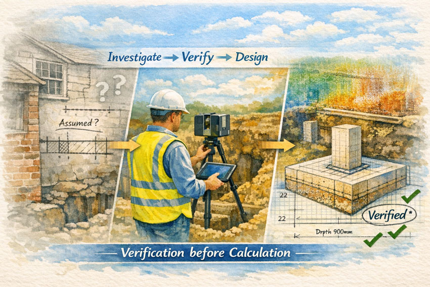
1. Investigation Is Part of Design
The media narrative highlights a simple truth: when we work with existing structures, the ground and foundations are not background details—they are primary design inputs.
Good practice means:
Treating site verification as a formal stage of the project
Making recommendations for geotechnical or structural checks early
Being clear about what is known and what is assumed
A design based only on drawings is never as reliable as one based on verified conditions.
2. Make Assumptions Visible
News coverage often shows that problems grow in the grey space between architect, engineer, and builder.
Helpful habits include:
Keeping an assumptions register shared by the whole team
Noting on drawings what has been confirmed on site
Setting clear triggers for further investigation
When assumptions have owners, risks have boundaries.
3. Communication Is a Structural Element
Many reported disputes stem less from technical ability and more from gaps in communication.
Engineers can lead by:
Discussing uncertainties openly at the start
Confirming decisions in writing after meetings
Encouraging contractors to report unexpected conditions
Good communication is often cheaper than remediation.
4. Scope Changes = Risk Changes
Renovations rarely stay the same as the first sketch. Media accounts of failures frequently involve projects that grew beyond the original intent.
Better process includes:
Re-checking engineering scope whenever the design evolves
Linking approvals to stages of investigation
Pricing verification as a real deliverable, not an afterthought
Clarity of scope is a form of structural strength.
5. Document the Story of the Project
Journalists and lawyers both rely on records to understand what happened.
For engineers, simple steps make a big difference:
Photos tied to inspection notes
Short design basis statements
Emails confirming client instructions
Sketches of as-found conditions
Documentation is not defensive—it is professional memory.
6. Respect the Interface Between Old and New
The media coverage repeatedly points to the moment where new work met an older structure. That interface is where uncertainty lives.
Practical responses:
Specific checks on existing footings before adding load
Independent review for heritage or unknown construction
Monitoring after completion to confirm behaviour
The junction between old and new deserves the most attention.
7. The Courage to Pause
Perhaps the most human lesson from the reports is that engineers sometimes need to slow a project down.
Saying:
“We need more information before proceeding”
is not obstruction—it is professionalism.
Organisations that support this courage protect clients and engineers alike.
Turning Headlines into Better Practice
The story covered by The Mercury and the subsequent industry commentary do not need to be read as cautionary tales. They can be read as learning opportunities:
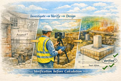
Investigate before you calculate
Make assumptions visible
Communicate uncertainty early
Document decisions clearly
Treat existing conditions with respect
These are the foundations of good engineering, long before concrete is poured.
Final Thought
Risk will always exist in renovation and brownfield work. What we control is the process we wrap around that risk.
When engineers focus on verification, transparency, and collaboration, projects become safer, clients are better served, and the profession grows stronger.
Good engineering is not only about correct numbers— it is about asking the right questions at the right time.
References
“Woodbridge homeowner wins huge payout after home cracked following two-storey extension” — The Mercury (Tasmania) 🔗 https://www.themercury.com.au/truecrimeaustralia/police-courts-tasmania/woodbridge-homeowner-wins-huge-payout-after-home-cracked-following-twostorey-extension/news-story/32fe411a57c2471be44962cba86100bd
Every Shutdown Matters – FARO LiDAR for As-Built Scanning
In heavy industry, a shutdown is not just another project milestone — it is the most expensive window on the calendar. Production stops, contractors mobilise, and every hour has a dollar value attached. When something does not fit, the cost is immediate and visible. This is why every shutdown matters, and why the approach to measurement and design before the outage has become critical.
Traditional site measurement relies on tape measures, sketches, and assumptions about existing conditions. In brownfield environments those assumptions are often wrong. Steel moves, plant is modified without drawings, and tolerances stack up over decades. Engineering-led 3D scanning, particularly using FARO terrestrial LiDAR for as-built capture, has changed the way shutdowns are planned and delivered.
From Guesswork to Measured Reality
A terrestrial LiDAR scanner captures millions of accurate points across an entire facility. Instead of a handful of manual dimensions, designers receive a complete digital replica of the plant — every beam, pipe, handrail and obstruction recorded in context. The result is a point cloud that becomes the single source of truth for engineering decisions.
The difference between scanning and traditional measurement is not just accuracy; it is completeness. A fitter with a tape can only measure what they think is relevant. A LiDAR scan measures everything, including the issues no one knew to look for: misaligned bases, out-of-square structures, undocumented modifications and clearance problems that would otherwise appear during the shutdown itself.
When this data is managed by engineers rather than survey technicians alone, it becomes more than a pretty model — it becomes a design tool.
Engineering-Led Scanning
Scanning by itself does not deliver value. The benefit comes when point clouds are interpreted through an engineering lens:
What tolerances actually matter?
Which surfaces are datums and which are cosmetic?
Where will fabrication interfaces occur?
How will the new design be installed within the shutdown sequence?
At Hamilton By Design we approach LiDAR capture as part of the engineering workflow, not a separate service. FARO scans are registered, cleaned and aligned to suit the specific design task — whether that is a conveyor upgrade, pump replacement, structural modification or access platform.
The aim is simple: design once, fit first time.
FARO LiDAR for As-Built Confidence
FARO terrestrial scanners are built for industrial environments. They capture long-range, high-density point clouds that allow designers to work with real conditions rather than idealised drawings. Typical applications include:
As-built capture of processing plants and mine infrastructure
Pipework routing and clash detection
Structural modifications and tie-ins
Equipment change-outs and baseplate verification
Access and safety improvements
By modelling new work directly over the point cloud, engineers can test installation paths, crane clearances and maintenance access long before the shutdown begins. Fabrication drawings are generated from a model that already “fits” the site.
The Cost of Getting It Wrong
During outages the smallest oversight becomes expensive:
A pipe spool 20 mm too long
A bracket that fouls an existing conduit
A motor base drilled to the wrong PCD
A platform clash discovered after hot works have started
Each of these problems triggers rework, additional labour, hot work permits and schedule delays. The true cost is rarely the part itself — it is the lost hours in the critical path.
Engineering-led LiDAR scanning attacks these risks at the source. By understanding existing geometry before fabrication begins, contractors arrive on site with components that have already been proven digitally.
Complementing LiDAR with Object Scanning
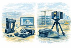
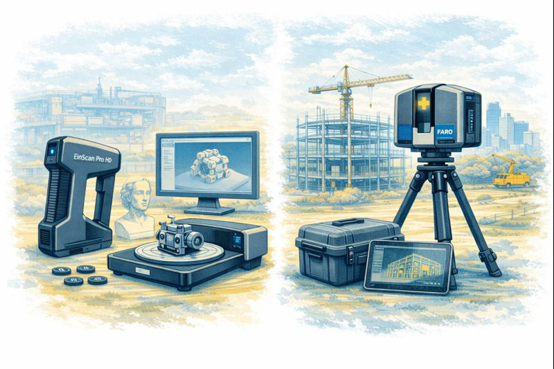
Large-scale LiDAR captures the plant; structured-light scanners such as EinScan capture the individual components within it. Motors, guards, cast housings and legacy parts can be digitised on the bench and integrated back into the LiDAR model. This two-tool approach supports:
Reverse engineering of obsolete components
Design of adapters and mounting brackets
Verification of replacement equipment
Creation of accurate fabrication models
The result is a seamless path from reality capture to parametric CAD in Fusion 360 or SolidWorks — guided by engineering intent rather than raw mesh data.
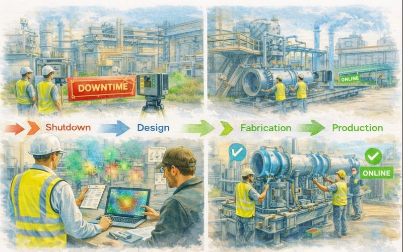
Planning the Shutdown Backwards
Successful outages are designed backwards from the installation day. FARO as-built scanning supports this process:
Pre-shutdown capture – full LiDAR survey of affected areas
Engineering modelling – new design built over the point cloud
Workshop fabrication – components manufactured to verified geometry
Dry fit digitally – clash and access checks completed
By the time the shutdown begins, the unknowns have been removed. Crews are executing a plan rather than solving problems in real time.
More Than Measurement
LiDAR point clouds are also powerful communication tools. Maintenance teams, project managers and contractors can visualise the work in context, improving safety and coordination. Decisions that once required multiple site visits can be made from the office with confidence.
For organisations moving toward digital twin strategies, as-built scans provide the foundation layer — an accurate spatial framework that future projects can reference.
Why Every Shutdown Matters
In mining, manufacturing and energy sectors the shutdown window defines the success of the year. Budgets are tight, schedules are fixed, and tolerance for rework is zero. Engineering-led scanning recognises that reality capture is not an optional extra; it is risk management.
FARO LiDAR for as-builts delivers:
Reduced site hours
Fewer fabrication errors
Safer installation planning
Better collaboration between design and maintenance
Confidence that new work will integrate with old
Most importantly, it respects the fact that every shutdown matters.
Talk to Us
Hamilton By Design provides engineering-led LiDAR scanning across Sydney, the Central Coast and regional Australia, supporting brownfield upgrades, shutdown planning and reverse engineering.
If you’re preparing for an outage or plant modification, speak with our team about capturing accurate as-builts before the clock starts ticking.
EinScan vs LiDAR Terrestrial Laser Scanners – Choosing the Right Tool for Reality Capture
The rapid growth of 3D scanning has given engineers, fabricators and designers access to tools that were once limited to large survey companies. Today you can buy a compact EinScan structured-light scanner for a few thousand dollars or hire a FARO or Leica terrestrial LiDAR scanner capable of mapping an entire processing plant in an afternoon. Both are called “3D scanners,” yet they serve very different purposes. Understanding the difference between EinScan-style scanners and terrestrial LiDAR systems is essential before investing time or money into reality capture.
Two Technologies, Two Different Jobs
EinScan scanners, produced by SHINING 3D, are primarily structured-light or short-range laser scanners. They project patterns of light onto an object and use cameras to interpret how that light deforms across the surface. The result is a dense mesh model of the object—typically exported as STL, OBJ or PLY files. EinScan units are designed for objects you can walk around, such as mechanical parts, castings, plastic housings and small assemblies.
Terrestrial LiDAR scanners such as the FARO Focus, Leica RTC360 or Trimble X-series operate on a completely different principle. These instruments sit on a tripod and fire millions of laser pulses across a 360-degree field, measuring the time it takes for each pulse to return. The output is a georeferenced point cloud containing precise XYZ coordinates for everything the laser can see—buildings, structures, conveyors, tanks, pipework and terrain.
Calling both devices “3D scanners” is like calling a vernier caliper and a total station the same tool. They both measure, but at entirely different scales.
Scale and Range
The first and most obvious difference is working range. An EinScan handheld unit is comfortable scanning parts from a few centimetres up to perhaps three or four metres. It is ideal for a gearbox housing on a bench or the plastic bumper of a vehicle. Once the object grows larger than a small room, the scanner begins to lose tracking and accuracy.
A terrestrial LiDAR scanner is built for the opposite end of the spectrum. A FARO Focus S-series can capture data from 0.6 metres out to 70 metres or more, mapping entire buildings or industrial sites from a single setup. Multiple scans are then registered together to create a complete digital twin of a facility.
For workshops and machine shops the question becomes simple: Are you scanning an object, or are you scanning a place? Objects suit EinScan; places suit LiDAR.
Accuracy and Tolerance Expectations
Manufacturers often quote impressive numbers, but real-world accuracy must be considered.
EinScan desktop and handheld systems typically achieve 0.05–0.2 mm accuracy on small parts when conditions are ideal.
Terrestrial LiDAR scanners deliver around ±1 mm to ±3 mm accuracy over distance.
At first glance EinScan appears “more accurate,” but this is only true at short range. A LiDAR scanner maintains consistent accuracy across tens of metres, something structured-light devices simply cannot do.
For precision mechanical components—bearing fits, machined bores, threaded holes—neither technology replaces traditional metrology tools. Scanning excels at capturing shape and context, while micrometers and CMMs remain the authority for tolerance verification.
Type of Data Produced
EinScan produces mesh files made from millions of tiny triangles. These are excellent for visualisation and 3D printing but contain no intelligence about holes, planes or cylinders. CAD systems like SolidWorks or Fusion 360 cannot directly convert these meshes into editable parametric models without additional reverse-engineering work.
LiDAR scanners generate point clouds—individual points with coordinates and often colour values. Point clouds are perfect for surveying, clash detection, volume calculations and as-built documentation. They are not intended to be edited like CAD models; instead, engineers build new geometry over the top using the cloud as reference.
Understanding this distinction avoids disappointment. Neither scanner delivers a “one-click CAD model.” Human engineering judgement is always required.
Surface and Environmental Limitations
EinScan technology relies on optical cameras and projected light, which introduces several practical limitations:
Shiny or black surfaces are difficult to capture
Transparent plastics confuse the cameras
Deep holes and narrow slots are often missed
Sunlight can overpower the projected pattern
Tracking can be lost on large flat surfaces
LiDAR systems are more tolerant of environment. They can operate outdoors, in dusty workshops and over long distances. However, they also struggle with highly reflective materials such as polished stainless steel or glass, and they require careful setup to avoid shadows and occlusions.
Workflow Considerations
A typical EinScan workflow looks like this:
Prepare the part—often with scanning spray
Capture multiple passes
Clean and align the mesh
Export STL/OBJ
Rebuild geometry in CAD using the mesh as reference
This process suits reverse engineering of brackets, castings, vehicle parts and consumer products.
A LiDAR workflow is different:
Set up the scanner at multiple locations
Register scans together in software such as FARO Scene or Leica Cyclone
Classify and clean the point cloud
Use the cloud for measurements, modelling or BIM integration
This approach is ideal for as-built surveys, plant upgrades, brownfield design and digital twins.
Cost and Ownership
EinScan systems range from a few thousand to around twenty thousand dollars. They are accessible to small businesses and even serious hobbyists. Software is generally included, and the learning curve is manageable.
Terrestrial LiDAR scanners are capital equipment. Purchase prices often exceed $60,000–$100,000 before software, training and maintenance. For many companies it makes more sense to engage a specialist scanning provider when required.
Choosing the Right Tool
The decision should be driven by the problem you are solving:
Choose EinScan when you need to:
Create a bracket to fit an existing motor
Reverse engineer a plastic enclosure
Modify a vehicle component
Capture complex organic shapes
Produce meshes for 3D printing
Choose LiDAR when you need to:
Document an industrial facility
Design around existing plant and pipework
Perform clash detection for upgrades
Measure volumes and clearances
Create a site-wide digital twin
Many organisations ultimately use both. A LiDAR scan provides the big picture, while an EinScan captures detailed components within that environment.
Integration with CAD
Engineers often ask which scanner works best with SolidWorks or Fusion 360. The honest answer is that neither integrates directly into parametric CAD without intermediate steps. EinScan meshes require reverse-engineering tools or manual modelling. LiDAR point clouds usually pass through Autodesk Recap, FARO Scene or similar before being referenced in CAD.
Scanning is a method of collecting truth, not generating finished design. The value lies in reducing site visits, avoiding clashes and giving designers confidence about existing conditions.
Final Thoughts
EinScan scanners and terrestrial LiDAR systems are not competitors; they are complementary tools on the reality-capture spectrum. One excels at objects on a bench, the other at assets spread across hectares. Selecting the wrong tool leads to frustration, while choosing correctly can transform the way projects are delivered.
For Australian fabricators and engineers, the key question is simple: Are you capturing a part, or are you capturing a place? Answer that, and the choice between EinScan and LiDAR becomes clear.
Fabrication Integrated Modelling (FIM): Why It’s the Future for Local Fabricators
Why It Is the Future for Local Fabricators
The fabrication industry is undergoing a fundamental transformation. Increasing project complexity, tighter tolerances, compressed schedules, labour shortages, and rising material costs are placing unprecedented pressure on fabricators — particularly local workshops operating in competitive markets. At the same time, clients are demanding greater certainty: certainty of fit, certainty of schedule, and certainty of cost.
Traditional fabrication workflows, built around 2D drawings and manual interpretation, are no longer sufficient to meet these expectations. They rely heavily on experience, assumptions, and rework — all of which introduce risk. In this environment, Fabrication Integrated Modelling (FIM) is emerging not as a luxury, but as a necessity.
FIM represents a shift from drawing-based fabrication to model-driven fabrication, where a single, coordinated digital model governs design intent, fabrication detailing, procurement, machining, assembly, and installation. For local fabricators, this shift offers a path to higher productivity, improved margins, and long-term relevance in an evolving industry.
What Is Fabrication Integrated Modelling (FIM)?
Fabrication Integrated Modelling is a methodology where the fabrication model becomes the primary source of truth across the entire project lifecycle. Instead of treating design, drafting, fabrication, and installation as disconnected stages, FIM integrates them into a continuous digital workflow.
In an FIM environment:
Engineering intent is embedded directly into the model
Fabrication constraints are considered from the outset
Quantities, tolerances, and interfaces are defined digitally
Fabrication data flows directly to machines and shop documentation
Installation sequencing is validated before material is cut
The model is not merely a visual aid — it is a fully informed digital prototype of the fabricated asset.
From Drawings to Data: A Fundamental Shift
Historically, fabrication has relied on 2D drawings as the primary communication tool. These drawings require interpretation by drafters, trades, and supervisors, each introducing assumptions based on experience and context. While this approach has worked for decades, it becomes increasingly fragile as projects grow more complex.
Fabrication Integrated Modelling replaces interpretation with explicit data. Hole locations, weld preparations, connection details, clearances, and tolerances are all defined within the model. This reduces ambiguity and ensures that everyone — from estimator to machine operator — is working from the same information.
The result is a dramatic reduction in errors, clarifications, and rework.
Why FIM Is Gaining Momentum Now
Several industry pressures are accelerating the adoption of FIM:
Increasing complexity of industrial and infrastructure projects
Reduced tolerance for errors during shutdowns and brownfield upgrades
Labour shortages and loss of experienced trades
Higher expectations for schedule and cost certainty
Growing integration of CNC and automated fabrication equipment
FIM addresses these challenges by improving coordination, predictability, and efficiency at the source — before fabrication begins.
Key Benefits of Fabrication Integrated Modelling
Reduced Errors and Rework
Rework is one of the most significant drains on fabrication profitability. Errors discovered on the workshop floor or during installation often result in cascading impacts: delays, additional labour, material waste, and strained relationships with clients.
By resolving interfaces, clashes, and tolerances digitally, FIM enables fabricators to identify and eliminate issues before steel is cut. Assemblies are tested virtually, connections are validated, and fit-up risks are significantly reduced.
This proactive approach shifts problem-solving upstream, where changes are faster, cheaper, and less disruptive.
Improved Fabrication Efficiency and Throughput
Fabrication speed is not achieved by rushing work — it is achieved by removing uncertainty. FIM provides clarity on what needs to be fabricated, in what order, and to what tolerance.
Benefits include:
Clear fabrication sequencing
Reduced downtime waiting for clarifications
Better planning of labour and machine utilisation
More predictable workshop flow
Local fabricators using FIM often report smoother operations, fewer interruptions, and a higher percentage of “right-first-time” components.
Better Use of Skilled Labour
Skilled trades are becoming harder to find and retain. Fabrication Integrated Modelling helps maximise the value of skilled workers by giving them better information, not more guesswork.
Fitters receive assemblies that align as expected. Welders focus on quality rather than correcting geometry. Supervisors make decisions based on accurate model data rather than assumptions. Apprentices gain clarity and confidence by working from model-based instructions.
Rather than replacing experience, FIM captures and amplifies it.
Seamless Integration with CNC and Fabrication Equipment
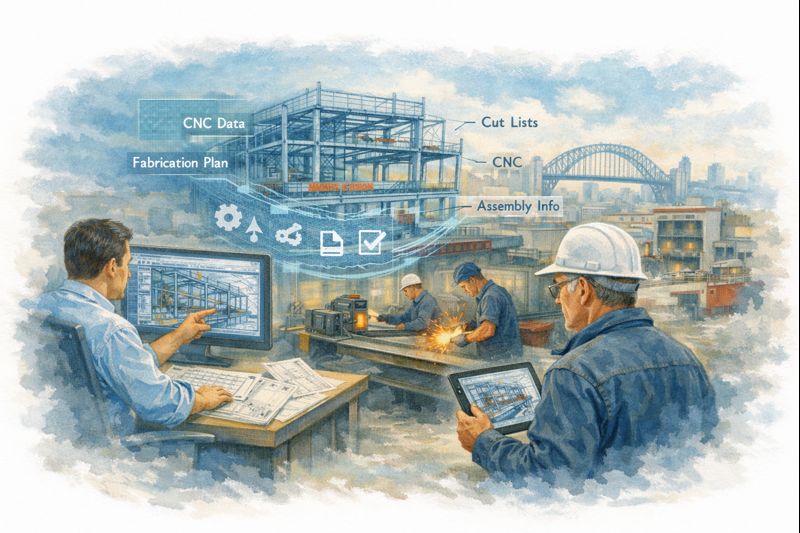
One of the strongest advantages of FIM is its ability to connect directly with modern fabrication equipment. The same model used for coordination and verification can generate machine-ready data, including:
NC files for beam lines and plate processors
Cut lists and nesting data
Part numbers and assembly marks
Machining references
This eliminates duplication of effort and reduces the risk of transcription errors. It also shortens the time between design approval and fabrication start, improving responsiveness to project changes.
Competitive Advantage for Local Fabricators
Local fabricators often compete with offshore suppliers on price alone — a contest that is difficult to win. FIM allows local workshops to compete on value rather than cost.
Key differentiators enabled by FIM include:
Faster response to changes
Higher confidence in fit-up for complex or brownfield sites
Reduced installation risk
Stronger collaboration with engineers and constructors
When site conditions change — as they inevitably do — local fabricators using FIM can adapt quickly, update models, and deliver revised components without significant disruption. This agility is a powerful advantage over remote fabrication alternatives.
FIM in Brownfield and Upgrade Projects
Brownfield projects present some of the greatest challenges in fabrication. Existing assets rarely match legacy drawings, and tolerances are often tight. Discovering misalignment during installation can result in costly delays and extended shutdowns.
Fabrication Integrated Modelling, often combined with accurate site capture, allows fabricators to design and fabricate components that align with actual site conditions rather than assumptions.
This approach reduces:
On-site modifications
Temporary works
Installation delays
Safety risks associated with forced fit-ups
For local fabricators servicing industrial plants and operational facilities, FIM is rapidly becoming an expected capability.
Financial Benefits: Protecting Margins, Not Just Schedules
While FIM is often associated with speed and accuracy, its most important benefit may be margin protection.
Model-based workflows enable:
More accurate pricing through reliable quantities
Reduced contingency allowances
Predictable labour and machine hours
Lower material waste
Fewer disputes and variations
By increasing certainty, FIM allows fabricators to price work confidently rather than defensively. Over time, this leads to healthier margins and more sustainable operations.
Earlier Engagement and Better Project Outcomes
Fabricators who adopt FIM often find themselves involved earlier in projects. Engineers and asset owners increasingly recognise the value of fabrication input during design development.
Early collaboration enables:
Design for manufacture and assembly
Smarter connection strategies
Reduced installation complexity
Improved safety outcomes
This shifts the fabricator’s role from reactive supplier to active project partner, strengthening relationships and improving project outcomes for all parties.
Overcoming Barriers to Adoption
Adopting Fabrication Integrated Modelling requires investment — not only in software and systems, but in people and processes. Common challenges include:
Training requirements
Changes to established workflows
Initial productivity adjustments
Cultural resistance to new methods
Successful fabricators address these challenges incrementally. They start with pilot projects, focus on repeatable wins, and work closely with engineering and modelling partners to build capability over time.
The risk of maintaining outdated workflows is increasingly greater than the risk of change.
The Future of Fabrication: Integrated Digital Ecosystems
FIM is not the final destination — it is the foundation for a more connected fabrication industry. As digital maturity increases, fabrication models will increasingly link to:
Digital twins
Quality assurance records
Traceability and compliance systems
Asset management platforms
Automated inspection and verification
In this future, the fabrication model becomes a long-term asset, supporting not only construction but operation and maintenance.
Why Fabrication Integrated Modelling Is the Future for Local Fabricators
Local fabrication is not disappearing — it is evolving. Workshops that continue to rely solely on 2D drawings and manual processes will face increasing pressure from cost, risk, and competition. Those that embrace Fabrication Integrated Modelling will position themselves for long-term success.
By adopting FIM, local fabricators can:
Deliver higher quality with greater confidence
Reduce rework and wasted effort
Protect margins in competitive markets
Strengthen relationships with engineers and clients
Build resilient, future-ready businesses
Fabrication Integrated Modelling is not about replacing trades or experience. It is about supporting them with better information, clearer intent, and integrated workflows.
For local fabricators willing to invest in capability and collaboration, FIM is not just the future — it is the pathway to remaining relevant, competitive, and profitable in an increasingly digital industry.
To provide the best experiences, we use technologies like cookies to store and/or access device information. Consenting to these technologies will allow us to process data such as browsing behaviour or unique IDs on this site. Not consenting or withdrawing consent, may adversely affect certain features and functions.
Functional
Always active
The technical storage or access is strictly necessary for the legitimate purpose of enabling the use of a specific service explicitly requested by the subscriber or user, or for the sole purpose of carrying out the transmission of a communication over an electronic communications network.
Preferences
The technical storage or access is necessary for the legitimate purpose of storing preferences that are not requested by the subscriber or user.
Statistics
The technical storage or access that is used exclusively for statistical purposes.The technical storage or access that is used exclusively for anonymous statistical purposes. Without a subpoena, voluntary compliance on the part of your Internet Service Provider, or additional records from a third party, information stored or retrieved for this purpose alone cannot usually be used to identify you.
Marketing
The technical storage or access is required to create user profiles to send advertising, or to track the user on a website or across several websites for similar marketing purposes.