From 3D Scanning to Digital Twins: The Next Step in Mining Data

Mining is evolving faster than ever.
What was once an industry defined by physical muscle โ€” haul trucks, crushers, conveyors โ€” is now being transformed by data intelligence, digital modelling, and real-time insight.

At the heart of this transformation lies a quiet revolution: 3D scanning.
Once used primarily for design verification or plant modification, scanning is now the gateway technology that feeds the emerging world of digital twins โ€” live, data-driven replicas of mine assets that help engineers predict, plan, and optimise before problems occur.

At Hamilton By Design, weโ€™ve spent years scanning and modelling chutes, hoppers, and material-handling systems across Australiaโ€™s mining sector. Each project has shown us one thing clearly:

Scanning isnโ€™t just about geometry โ€” itโ€™s about knowledge.
And digital twins are the next logical step in turning that knowledge into action.


What Exactly Is a Digital Twin?

Think of a digital twin as the digital counterpart of a physical asset โ€” a chute, a conveyor, a processing plant, even an entire mine site.

Itโ€™s not a static 3D model; itโ€™s a dynamic, data-linked environment that mirrors the real system in near real time.
Sensors feed performance data into the twin: wear rates, temperature, vibration, flow speed, throughput. The twin then responds, updating its state and allowing engineers to simulate scenarios, forecast failures, and test design changes before touching the physical equipment.

In essence, a digital twin gives you a real-time window into the life of your assets โ€” one thatโ€™s predictive, not reactive.


How 3D Scanning Powers the Digital Twin

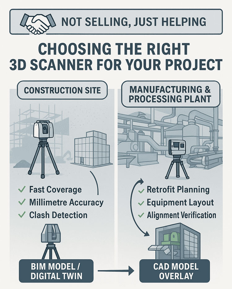
To create a digital twin, you first need an accurate foundation โ€” and thatโ€™s where 3D scanning comes in.
The twin can only be as good as the geometry beneath it.

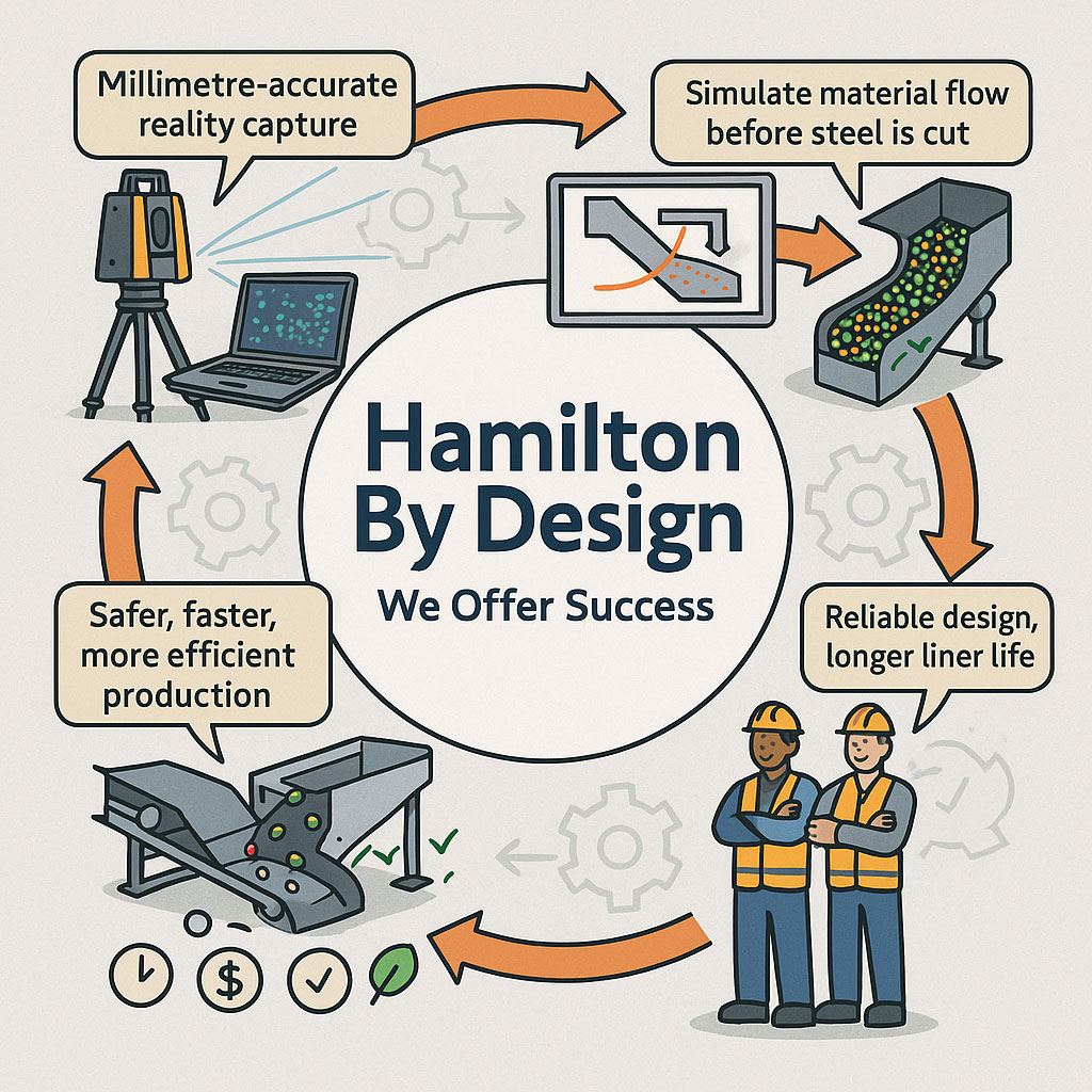
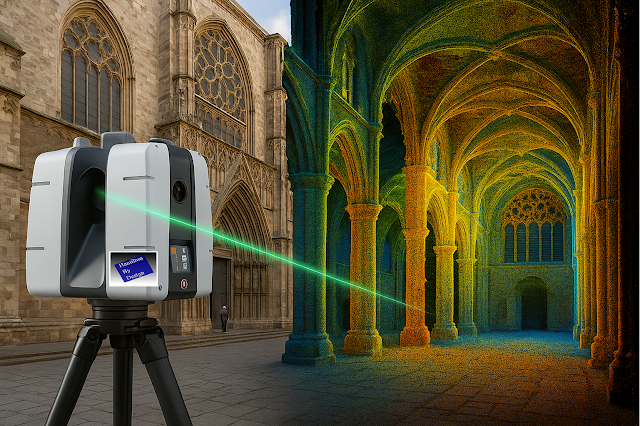
Laser scanning or LiDAR technology captures millimetre-accurate measurements of chutes, hoppers, crushers, conveyors, and processing structures.
This creates a precise 3D โ€œas-isโ€ model โ€” not what the plant was designed to be, but what it actually is after years of wear, repair, and modification.

That baseline geometry is then aligned with:

  • Operational data from sensors and PLCs (e.g. flow rates, temperatures, vibrations)
  • Material behaviour data from CFD and wear simulations
  • Design intent data from CAD and engineering archives

Once these layers are synchronised, the model becomes a living system โ€” continuously updated, measurable, and comparable to its physical twin.

You can see how we capture and prepare that foundation in our detailed article:
3D Scanning Chutes, Hoppers & Mining


From Reactive Maintenance to Predictive Performance

In most operations today, maintenance still works on a reactive cycle โ€” wait for a fault, shut down, repair, restart.
Itโ€™s expensive, unpredictable, and risky.

With digital twins, that model flips.
Instead of waiting for wear to become a failure, the twin uses real-time and historical data to forecast when parts will reach their limits.
The result is predictive maintenance โ€” planning shutdowns based on evidence, not emergency.

Imagine being able to simulate how a chute will behave under new flow conditions, or when a liner will reach its critical wear thickness, before you commit to a shutdown.
Thatโ€™s not future-speak โ€” itโ€™s what forward-thinking operators are doing right now.

Every hour of avoided downtime can mean tens or even hundreds of thousands of dollars saved.
Even a modest 5 % reduction in unplanned outages can add millions to annual output.


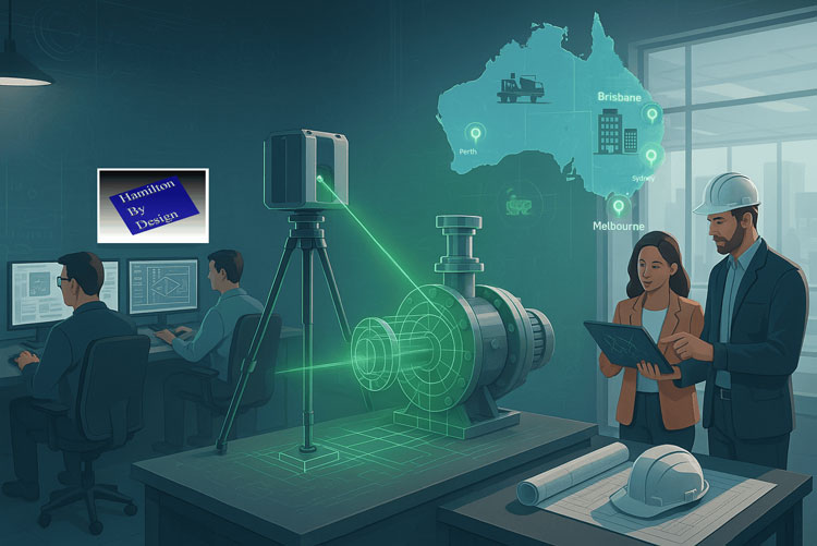
Integrating Scanning, Simulation, and Sensors

A full digital-twin workflow in mining usually includes four steps:

  1. Capture: 3D scanning provides the exact geometry of the asset.
  2. Model: Engineers integrate the geometry with CAD, CFD, and FEA models.
  3. Connect: Real-time data from sensors is linked to the model.
  4. Predict: Algorithms and engineers analyse the twin to predict future performance.

The power lies in connection.
Each new scan or dataset strengthens the model, improving its predictive accuracy. Over time, the digital twin evolves into a decision-support system for engineers, planners, and maintenance teams.


Real-World Applications Across the Mining Value Chain

1. Chute & Hopper Optimisation

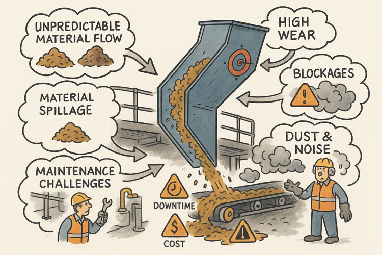
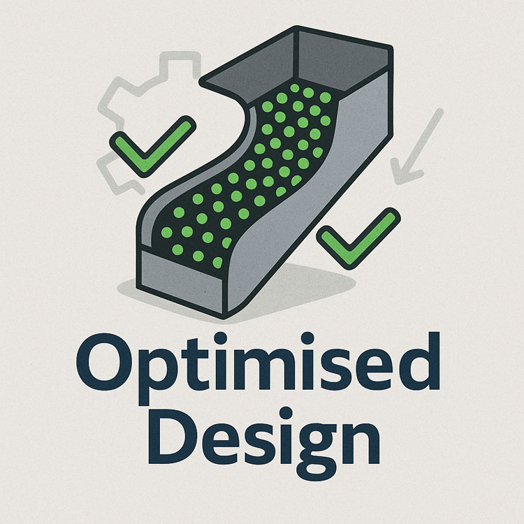
Flow issues, blockages, and uneven wear can be modelled digitally before modifications are made.
This reduces trial-and-error shutdowns and improves throughput reliability.

2. Conveyor Alignment

Scanning allows engineers to identify misalignment over kilometres of belting.
A digital twin can then simulate tracking and tension to prevent belt failures.

3. Crusher and Mill Wear

By combining periodic scans with wear sensors, operators can visualise material loss and forecast replacement schedules.

4. Structural Monitoring

3D scanning enables long-term comparison between โ€œas-builtโ€ and โ€œas-maintainedโ€ geometry, detecting distortion or settlement early.

Each of these applications reinforces a core insight:

The line between mechanical engineering and data engineering is disappearing.


Why Digital Twins Matter for Australiaโ€™s Mining Future

Australiaโ€™s competitive advantage has always been resource-based.
But the next advantage will be knowledge-based โ€” how well we understand, model, and optimise those resources.

Digital twins represent that shift from raw extraction to engineering intelligence.
They help miners lower costs, reduce emissions, and improve safety, while extending asset life and reliability.

As Australia pushes toward decarbonisation and productivity targets, technologies like scanning and digital twinning will underpin the next generation of sustainable mining design.


The Hamilton By Design Approach

Our philosophy is simple: technology only matters if it serves engineering integrity.
Thatโ€™s why our process always begins with real-world problems โ€” not software.

  1. Field Capture: We conduct high-resolution 3D scans under live or shutdown conditions.
  2. Engineering Integration: Our designers and mechanical engineers turn that data into usable CAD and FEA models.
  3. Digital Twin Setup: We connect the digital model to operational data, creating a living reference that evolves with the asset.
  4. Continuous Support: We monitor, re-scan, and update as assets change.

This approach ensures every digital twin remains a tool for decision-making, not just a visualisation exercise.


A Connected Knowledge Chain

This article builds on our earlier discussion:


Digital Precision in Mining: How 3D Scanning Transforms Maintenance, Design, and Safety

That piece explored how scanning replaces manual measurement with safe, precise, data-rich modelling.
Digital twins take that same data and carry it forward โ€” connecting it to predictive insights and automated planning.

The flow looks like this:

3D Scan โ†’ Model โ†’ Digital Twin โ†’ Predict โ†’ Improve โ†’ Re-scan

Each loop makes the operation smarter, safer, and more efficient.


Lessons from Global Mining Leaders

  • Rio Tinto and BHP are already trialling digital twins for rail networks, conveyors, and entire processing plants.
  • Anglo American uses twin models to monitor tailings dam integrity, integrating LiDAR scans with geotechnical sensors.
  • Fortescue has explored twin-based predictive maintenance for haulage and fixed plant systems.

Internationally, countries like Finland and Canada have established digital-twin testbeds for mine ventilation, environmental monitoring, and process control โ€” demonstrating that twinning isnโ€™t a luxury, itโ€™s a competitive necessity.


Looking Forward: The Road to Real-Time Mines

The next decade will see digital twins move from project pilots to enterprise-wide ecosystems.
Future systems will integrate:

  • IoT sensors streaming continuous data
  • AI algorithms identifying anomalies in real time
  • Augmented-reality tools allowing operators to โ€œseeโ€ the twin overlaid on the physical plant

Combined, these will make mines safer, cleaner, and more efficient โ€” driven by data instead of downtime.


The Broader Economic Story

The technologyโ€™s value doesnโ€™t stop at the mine gate.
As digital twins become standard across energy, infrastructure, and manufacturing, Australiaโ€™s engineering capability grows alongside GDP.

Every dollar invested in scanning and twin development creates long-term dividends in productivity and sustainability.
By connecting our data and design skills to resource industries, we strengthen both our domestic economy and our global competitiveness.


Building Smarter, Safer, and More Predictable Mines

Mining will always be a physically demanding industry โ€” but its future will be defined by how intelligently we manage that physicality.

From the first laser scan to the fully connected digital twin, every step tightens the link between information and performance.

At Hamilton By Design, weโ€™re proud to stand at that intersection โ€” where mechanical precision meets digital innovation.
We help our clients not just capture data, but understand it โ€” turning measurements into models, and models into insight.

Because when you can see your mine in full digital clarity, you can shape its future with confidence.

Mechanical Engineering | Structural Engineering

Mechanical Drafting | Structural Drafting

3D CAD Modelling | 3D Scanning

Chute Design

SolidWorks Contractors in Australia

Hamilton By Design โ€“ Blog

Custom Designed – Shipping Containers

Coal Chute Design

Mechanical Engineers in Sydney

Choosing the Right 3D Scanner for Construction, Manufacturing, and Mining Projects

At Hamilton By Design, we know that 3D scanning has become an essential tool for modern engineering โ€” from capturing as-built conditions on construction sites to modeling complex processing plants and validating manufacturing layouts. But not all scanners are created equal, and selecting the right technology is crucial to getting reliable data and avoiding costly surprises later in the project.

3D Scanning for Construction Sites

For construction and infrastructure projects, coverage and speed are the top priorities. Terrestrial Laser Scanning (TLS) and LiDAR systems like the FARO Focus S70 are ideal for quickly capturing entire job sites with millimetre-level accuracy. These scanners allow engineers and project managers to:

  • Verify as-built conditions against design models
  • Detect clashes early in the process
  • Support accurate quantity take-offs and progress documentation

TLS works well in tough environments โ€” dust, sunlight, and complex geometry โ€” making it a perfect fit for active building sites.

3D Scanning for Manufacturing & Processing Plants

When it comes to manufacturing facilities and mining processing plants, accuracy and detail matter even more. Scans are often used for:

  • Retrofit planning and clash detection in tight plant rooms
  • Structural steel and conveyor alignment checks
  • Equipment layout for expansion projects

Here, combining TLS with feature-based CAD modeling allows us to deliver data that is usable for engineering design, ensuring that new equipment fits exactly as intended.

Infographic titled โ€˜Choosing the Right 3D Scanner for Your Projectโ€™ with the tagline โ€˜Not Selling, Just Helping.โ€™ The left side shows a construction site with a tripod-mounted 3D scanner and benefits listed: fast coverage, millimetre accuracy, and clash detection, leading to BIM model or digital twin outputs. The right side shows a manufacturing and processing plant with a scanner and benefits: retrofit planning, equipment layout, and alignment verification, leading to CAD model overlay results

Weโ€™re Here to Help

Hamilton By Design doesnโ€™t sell scanners โ€” we focus on providing unbiased, engineering-driven advice. If youโ€™re unsure which scanning approach is right for your project, weโ€™re happy to share our experience and guide you toward the best solution.

Feel free to get in touch to discuss your project needs โ€” whether itโ€™s a construction site, manufacturing facility, or processing plant, we can help you turn accurate scan data into actionable engineering insights.

3D Scanning for Construction Sites |  3D Scanning for Manufacturing | 3D Scanning for Processing Plants

Mechanical Engineering | Structural Engineering

Mechanical Drafting | Structural Drafting

3D CAD Modelling | 3D Scanning

Unlocking the Future of Design

Illustration of an engineering workspace where a tripod-mounted 3D LiDAR scanner captures a green point-cloud of an industrial pump assembly. Two engineers review scan data on a tablet beside technical drawings, while two others model components on computer workstations. A digital map of Australia is displayed in the background, highlighting Hamilton By Designโ€™s service locations including Perth, Brisbane, Sydney, and Melbourne. The scene emphasises advanced 3D scanning, digital engineering, and nationwide support.

3D Laser Scanning & Mechanical Engineering Solutions

In todayโ€™s fast-paced engineering and construction industries, precision and efficiency are everything. Whether youโ€™re managing a large-scale infrastructure project in Brisbane, creating a mechanical prototype in Perth, or needing accurate as-built data for a site in the Hunter Valley, 3D laser scanning and expert mechanical design services are game changers.

At Hamilton By Design, we specialise in connecting cutting-edge scanning technology with skilled mechanical designers and structural drafting services to deliver seamless, accurate solutions for every stage of your project.


The Power of 3D Laser Scanning

3D laser scanning is transforming the way engineers, architects, and manufacturers work. By capturing millions of data points with millimetre accuracy, laser scanning creates a highly detailed 3D representation of your asset, site, or structure.

Our team provides 3D laser scanning services in Perth, Brisbane, and Melbourne, as well as laser scanning in the Hunter Valley, helping clients save time and avoid costly rework. This technology is ideal for:

  • Capturing as-built conditions before design or construction.
  • Supporting plant upgrades and facility expansions.
  • Documenting heritage structures and complex geometries.
  • Reducing site visits with accurate digital models.

Reverse Engineering & Mechanical Design

In addition to scanning, we offer reverse engineering services in Perth and beyond. By combining point cloud data with CAD modelling, we can recreate components, optimise designs, and prepare manufacturing-ready files.

Our mechanical engineers and mechanical designers bring years of experience in 3D mechanical engineering, design and manufacturing mechanical engineering, and problem-solving for a wide range of industries. From bespoke machinery to process equipment, we deliver solutions that work.


Structural Drafting & Project Support

No project is complete without clear, accurate documentation. Our skilled drafters at Hamilton By Design provide high-quality structural drafting services that integrate seamlessly with your workflows.

Whether you need shop drawings, fabrication details, or BIM-ready models, our team ensures every line and dimension is correct โ€” saving you time and cost on-site.


Why Choose Hamilton By Design?

  • Nationwide Reach: Serving clients with 3D scanning services in Perth, Brisbane, and Melbourne, and supporting projects in the Hunter Valley.
  • Complete Solutions: From scanning to modelling to mechanical engineering design.
  • Accuracy & Efficiency: Reduce project risk and improve decision-making with reliable data.
  • Experienced Team: Skilled mechanical engineers and drafters who understand your industry.

Hamilton By Design logo displayed on a blue tilted rectangle with a grey gradient background

Ready to Get Started?

If youโ€™re looking for mechanical engineering companies that deliver precision, innovation, and reliability, Hamilton By Design is ready to help. Whether you need laser scanning in Perth or Brisbane, structural drafting, or full mechanical design services, our team can support your next project from concept to completion.

Contact us today to discuss your project requirements and find out how our 3D laser scanning and mechanical engineering design solutions can save you time and money.


Name
Would you like us to arrange a phone consultation for you?
Address

Why 3D Point Clouds + Expert Modelers Are a Game-Changer for Your Projects

Infographic illustrating the 3D project data workflow, showing LiDAR scanners and drones capturing millions of data points, a designer modelling on a computer, and project teams validating accurate 3D data, highlighting benefits such as speed, accuracy, cost savings and project success.

Level Up your 3D Scans

In todayโ€™s world, accuracy and efficiency can make or break a project. Whether youโ€™re working in architecture, construction, engineering, or product design, you need reliable data โ€” and you need it fast. Thatโ€™s where 3D point clouds come in.

But thereโ€™s an important catch: not all scans are created equal. The difference between an average scan and a great one often comes down to the person behind the scanner. Having someone who understands 3D modeling take the scans can dramatically improve your projectโ€™s accuracy, reliability, and overall success.

Letโ€™s break down why.


The Power of 3D Point Clouds

Point clouds are essentially millions of tiny data points that capture the shape of an object, room, or entire site. Together, they create a highly detailed digital snapshot of the real world.

Hereโ€™s why this matters:

  • Precision you can trust โ€“ Point clouds deliver incredibly detailed measurements, capturing even the smallest curves and angles.
  • Nothing gets missed โ€“ Multiple scan angles ensure a full, 360ยฐ view of your site or object.
  • Speed and efficiency โ€“ What used to take hours (or days) with manual measurements can be captured in minutes.
  • Built-in context โ€“ Youโ€™re not just getting numbers; youโ€™re getting a complete digital environment to work inside.
  • Future-proof data โ€“ Once you have a scan, you have a permanent record of your space, ready to use months or years later.

From clash detection to as-built verification, point clouds save time, reduce errors, and make collaboration across teams smoother than ever.


Why the Person Taking the Scan Matters

While technology is powerful, experience is what makes the results reliable. Having a skilled 3D modeler operate the scanner can be the difference between a good project and a great one.

Hereโ€™s why an expert makes all the difference:

  • They know what matters โ€“ A modeler understands which details are critical for your project and ensures theyโ€™re captured.
  • Fewer gaps, fewer surprises โ€“ Experienced pros know how to plan scan positions to cover every angle and avoid blind spots.
  • Cleaner, more accurate data โ€“ They reduce common issues like noise, misalignment, or missing sections that can throw off your model.
  • Time saved, headaches avoided โ€“ No one wants to redo a scan halfway through a project. A professional ensures you get it right the first time.
  • Confidence from start to finish โ€“ When you know your model is accurate, you can move forward with design and construction decisions without second-guessing.

In short: a great scanner operator doesnโ€™t just deliver data โ€” they deliver peace of mind.


The Bottom Line

3D point clouds are already transforming how projects are planned and delivered. But pairing them with an experienced 3D modeler takes things to the next level.

Youโ€™ll get better data, faster turnarounds, and a far lower risk of costly mistakes. And when your goal is to deliver projects on time, on budget, and with zero surprises, thatโ€™s an edge you canโ€™t afford to miss.

Hamilton By Design logo displayed on a blue tilted rectangle with a grey gradient background

3D Modelling | 3D Scanning | Point Cloud Scanning

Chute Design in the Mining Industry

Infographic showing Hamilton By Designโ€™s engineering workflow, including millimetre-accurate LiDAR reality capture, material-flow simulation, optimised chute designs, and safer, more efficient production outcomes. Two workers in PPE highlight reliable design and longer liner life, with icons representing time, cost and quality benefits.

Getting Coal, Hard Rock, and ROM Material Flow Right

Chute design is one of the most critical yet challenging aspects of mining and mineral processing. Whether you are handling coal, hard rock ore, or raw ROM material, chutes and transfer stations are the unsung workhorses of every operation. When designed well, they guide material smoothly, minimise wear, and keep conveyors running. When designed poorly, they cause blockages, spillage, excessive dust, and expensive downtime.

Modern chute design has moved far beyond rules of thumb and back-of-the-envelope sketches. Today, successful projects rely on accurate as-built data, particle trajectory analysis, and advanced Discrete Element Method (DEM) simulation to predict, visualise, and optimise material flow before steel is cut. In this article, we explore why these tools have become essential, how they work together, and where software can โ€” and cannot โ€” replace engineering judgement.


Illustration showing common problems with poorly designed material-handling chutes. A chute discharges material onto a conveyor while issues are highlighted around it: unpredictable material flow, material spillage, maintenance challenges, high wear, blockages, and dust and noise. Warning icons for downtime and cost appear on the conveyor, and workers are shown dealing with the resulting hazards and maintenance tasks.

The Challenge of Chute Design

Coal and hard rock have very different flow behaviours. Coal tends to be softer, generate more dust, and be prone to degradation, while hard rock is more abrasive and can damage chutes if impact angles are not controlled. ROM material adds another level of complexity โ€” oversize lumps, fines, and moisture variation can cause hang-ups or uneven flow.

Chute design must balance several competing objectives:

  • Control the trajectory of incoming material to reduce impact and wear
  • Prevent blockages by maintaining flowability, even with wet or sticky ore
  • Manage dust and noise to meet environmental and workplace health requirements
  • Fit within existing plant space with minimal modification to conveyors and structures
  • Be maintainable โ€” liners must be accessible and replaceable without excessive downtime

Meeting all these goals without accurate data and simulation is like trying to design in the dark.


Illustrated graphic showing a tripod-mounted 3D laser scanner capturing millimetre-accurate as-built data in an industrial plant with conveyors and walkways. Speech bubbles highlight issues such as โ€œOutdated drawings donโ€™t tell the full storyโ€ and โ€œModifications rarely get documented.โ€ The scan data is shown being visualised on a laptop, with notes describing full coverage of conveyors, walkways, and services. Benefits listed along the bottom include faster data collection, fewer site revisits, safer shutdowns, accurate starting point for design simulation, and safer outcomes that ensure designs fit first time.

Capturing the Truth with 3D Scanning

The first step in any successful chute project is to understand the as-built environment. In many operations, drawings are outdated, modifications have been made over the years, and the real plant geometry may differ from what is on paper. Manual measurement is slow, risky, and often incomplete.

This is where 3D laser scanning changes the game. Using tripod-mounted or mobile LiDAR scanners, engineers can capture the entire transfer station, conveyors, surrounding steelwork, and services in a matter of hours. The result is a dense point cloud with millimetre accuracy that reflects the true state of the plant.

From here, the point cloud is cleaned and converted into a 3D model. This ensures the new chute design will not clash with existing structures, and that all clearances are known. It also allows maintenance teams to plan safe access for liner change-outs and other work, as the scanned model can be navigated virtually to check reach and access envelopes.


Understanding Particle Trajectory

Once the physical environment is known, the next challenge is to understand the particle trajectory โ€” the path that material takes as it leaves the head pulley or previous transfer point.

Trajectory depends on belt speed, material characteristics, and discharge angle. For coal, fine particles may spread wider than the coarse fraction, while for ROM ore, large lumps may follow a ballistic path that needs to be controlled to prevent impact damage.

Accurately modelling trajectory ensures that the material enters the chute in the right location and direction. This minimises impact forces, reducing wear on liners and avoiding the โ€œsplashโ€ that creates spillage and dust. It also prevents the material from hitting obstructions or dead zones that could lead to build-up and blockages.

Modern software can plot the trajectory curve for different loading conditions, providing a starting point for chute geometry. This is a critical step โ€” if the trajectory is wrong, the chute design will be fighting against the natural path of the material.


The Power of DEM Simulation

While trajectory gives a first approximation, real-world flow is far more complex. This is where Discrete Element Method (DEM) simulation comes into play. DEM models represent bulk material as thousands (or millions) of individual particles, each following the laws of motion and interacting with one another.

When a DEM simulation is run on a chute design:

  • You can visualise material flow in 3D, watching how particles accelerate, collide, and settle
  • Impact zones become clear, showing where liners will wear fastest
  • Areas of turbulence, dust generation, or segregation are identified
  • Build-up points and potential blockages are predicted

This allows engineers to experiment with chute geometry before fabrication. Angles can be changed, ledges removed, and flow-aiding features like hood and spoon profiles or rock-boxes optimised to achieve smooth, controlled flow.

For coal, DEM can help ensure material lands gently on the receiving belt, reducing degradation and dust. For hard rock, it can ensure that the energy of impact is directed onto replaceable wear liners rather than structural plate. For ROM ore, it can help prevent oversize lumps from wedging in critical locations.


Illustration of an optimised chute design showing material flow represented by green particles, with check marks and gear icons indicating improved efficiency and engineered performance.

๐Ÿ–ฅ Strengths and Limitations of Software

Modern DEM packages are powerful, but they are not magic. Software such as EDEM, Rocky DEM, or Altairโ€™s tools can simulate a wide range of materials and geometries, but they rely on good input data and skilled interpretation.

Key strengths include:

  • Ability to model complex, 3D geometries and particle interactions
  • High visualisation power for communicating designs to stakeholders
  • Capability to run multiple scenarios (different feed rates, moisture contents, ore types) quickly

However, there are limitations:

  • Material calibration is critical. If the particle shape, friction, and cohesion parameters are wrong, the results will not match reality.
  • Computational cost can be high โ€” detailed simulations of large chutes with millions of particles may take hours or days to run.
  • Engineering judgement is still needed. Software will not tell you the โ€œbestโ€ design โ€” it will only show how a proposed design behaves under given conditions.

Thatโ€™s why DEM is best used as part of a holistic workflow that includes field data, trajectory analysis, and experienced design review.


From Model to Real-World Results

When the simulation results are validated and optimised, the design can be finalised. The point cloud model ensures the chute will fit in the available space, and the DEM results give confidence that it will perform as intended.

This means fabrication can proceed with fewer changes and less risk. During shutdown, installation goes smoothly, because clashes have already been resolved in the digital model. Once commissioned, the chute delivers predictable flow, less spillage, and longer liner life.


Why It Matters More Than Ever

Todayโ€™s mining operations face tighter production schedules, stricter environmental compliance, and increasing cost pressures. Downtime is expensive, and the margin for error is shrinking.

By combining 3D scanning, trajectory modelling, and DEM simulation, operations can move from reactive problem-solving to proactive improvement. Instead of waiting for blockages or failures, they can design out the problems before they occur, saving both time and money.


Partnering for Success

At Hamilton by Design, we specialise in turning raw site data into actionable insights. Our team uses advanced 3D scanning to capture your transfer stations with precision, builds accurate point clouds and CAD models, and runs calibrated DEM simulations to ensure your new chute design performs from day one.

Whether youโ€™re working with coal, hard rock, or ROM ore, we help you deliver designs that fit first time, reduce maintenance headaches, and keep production running.

Contact us today to see how our integrated scanning and simulation workflow can make your next chute project safer, faster, and more reliable.

Mechanical Engineering | Structural Engineering

Mechanical Drafting | Structural Drafting

3D Laser Scanning | 3D CAD Modelling | 3D Scanning

Chute Design

SolidWorks Contractors in Australia

Hamilton By Design โ€“ Blog

Consulting Engineers

About Us โ€“ Hamilton By Design

Hamilton By Design | 3D Scanning | Sydney | Perth | Brisbane | Mount Isa | Lidar Scanning

Contact us

3D Scanning

How 3D Laser Scanning is Redefining Reality for Design, Construction & Heritage

Imagine standing before a centuries-old cathedral, where every carved arch, every stained-glass pane, every weathered stone holds centuries of stories. Capturing its true form and condition with tape measure and camera? Tedious and prone to errors. But with 3D laser scanning, you can digitally freeze every detailโ€”down to the imperfectionsโ€”turning reality into an exact, manipulable model.

In an age where precision, speed, and data-driven decisions are non-negotiable, 3D laser scanning is no longer โ€œnice to haveโ€โ€”itโ€™s essential. Letโ€™s explore what it is, why itโ€™s transformative, where itโ€™s being used most powerfully, and how you can harness its potential.

What Is 3D Laser Scanning?

At its core, 3D laser scanning sometimes called terrestrial laser scanning, (TLS) is the emission of laser pulses toward surfaces, recording the time it takes for those pulses to bounce back. From that comes a dense โ€œpoint cloudโ€ โ€” billions of precise data points mapping shape, texture, orientation, and distance.

These point clouds become high-fidelity models, maps, meshes, or BIM ready files. Whether youโ€™re scanning building exteriors, interiors, or industrial components, the result is more than just imageryโ€”itโ€™s measurable, analyzable geometry.

How It Works โ€” The Process

  1. Preparation & Planning

    Define what you need: the level of detail (LOD), resolution, range, and whether external conditions (light, weather) will interfere.

  2. Data Capture

    Position the scanner at multiple stations to cover all surfaces. Use targets or reference markers for alignment and capture with overlapping scans.

  3. Processing & Registration

    Merge scans to align them properly, clean noise, filter out irrelevant data (like people, moving objects), calibrate.

  4. Post-processing & Deliverables

    Convert point clouds into usable outputsโ€”floorplans, sections, elevations, 3D meshes, BIM models, virtual walkthroughs. Run analyses (clash detection, deformation etc.).

  5. Integration & Use

    Use the data in design, restoration, facility management, or documentation. The quality of integration (into BIM, GIS, CAD) is key to unlocking value.

ย 

Key Benefits

Benefit What It Means in Practice Real-World Impact
Extreme Precision Sub-millimetre to millimetre accuracy depending on the scanner and conditions. Less rework. Better fit for retrofit, renovation, or mechanical systems in tight tolerances.
Speed + Efficiency Collect large amounts of spatial data in far less time than traditional measurement. Faster project turnaround. Reduced site time costs.
Non-Contact / Low Disruption Good for fragile structures, hazardous or difficult-to-access places. Preserves integrity of heritage buildings; safer for workers.
Comprehensive Documentation Full visual & geometric context. Informs future maintenance. Acts as an archival record.
Better Decision Making & Conflict Detection Early clash detection; scenario simulation; what-if modelling. Avoids costly mistakes; helps build consensus among stakeholders.
Enhanced Visualisation & Communication Stakeholders can see exactly what exists vs. whatโ€™s being proposed. Improves client buy-in, regulatory approvals, fundraising.

ย 

Applications: Where It Shines

  • Architecture & Renovation: As-built models, restoration of heritage sites.

  • Infrastructure & Civil Engineering: Bridges, tunnels, rail track alignments.

  • Industrial & Manufacturing: Machine part audits, reverse-engineering, plant layout.

  • Heritage & Preservation: Documenting fragile monuments, archaeological sites.

  • Facility Management: Digital twins, maintenance, asset tracking.

  • Environment & Surveying: Terrain mapping, forestry, flood risk mapping (especially when combined with aerial systems or mobile scanning).

Challenges & Best Practices

Nothing is perfect. To get the most out of 3D laser scanning, anticipate and mitigate:

  • Environmental factors: Light, dust, rain, reflective surfaces can introduce noise.

  • Data overload: Massive point clouds are large; need strong hardware & efficient workflows.

  • Alignment & registration errors: Overlaps, control points, and calibration are vital.

  • Skill & Planning: Good operators + good planning = much better outcomes.

Key best practices:

  • Use reference targets for precise registration.

  • Capture overlap of 30-50% between scan positions.

  • Break project into manageable segments.

  • Clean noise early.

  • Think ahead about deliverables and how clients will use the data (design, BIM, VR etc.).

Case Studies & Stories

  • Heritage in Danger: A cathedral in Europe threatened by pollution and structural decay was laser scanned. The point cloud revealed minute deformations, enabling an accurate restoration planโ€”saving costs and preserving history.

  • Infrastructure Efficiency: A civil engineering firm reduced design clashes by 80% on a complex highway project by integrating scans with their BIM workflow.

  • Industrial Switch-Over: Manufacturing plant layout was reconfigured using scan data; downtime reduced because the virtual model matched reality better than the old blueprints.

Software, Tools & Ecosystem

While scanners are vital, the software ecosystem is what unlocks value. Tools that turn raw data into actionable insights include:

  • Reality capture tools (processing point clouds).

  • BIM / CAD integration (e.g. Revit, AutoCAD).

  • Visualization tools (VR, AR, walkthrough).

  • Data sharing & collaboration platforms.

  • Cloud storage / processing if large point clouds.

SaaS/cloud-based workflows are increasingly important to share among remote teams, facilitate stakeholder review, and ensure data is accessible beyond just technical users.

Why It Matters Now

  • Global pressures (heritage, sustainability, faster build cycles, remote work) are raising the bar.

  • Clients expect transparency, accuracy, minimized risk.

  • Regulatory compliance and โ€œas-builtโ€ requirements are stricter.

  • Digital twins & smart infrastructure demand high fidelity data.

3D laser scanning acts as a bridge: between physical world and digital twin; between heritage past and future; between design promise and build reality. Ifย you have a survey scan and want to make sense of point cloud data, contact Hamilton By Design

ย 
ย 
ย 
ย 

Our clients:

Name
Would you like us to arrange a phone consultation for you?
Address