Mechanical Engineering | 3D Scanning | 3D Modelling
Tag: clash-detection
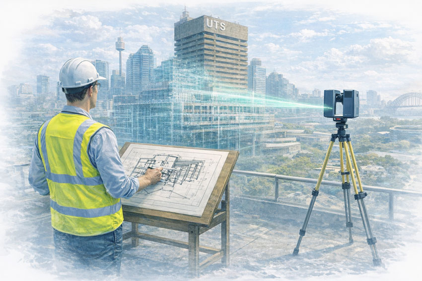
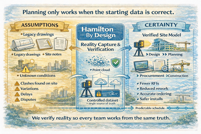
Hamilton By Design provides clash detection services using 3D LiDAR point clouds, CAD models and BIM data to identify spatial conflicts before fabrication or installation begins.
Clash detection is particularly valuable for brownfield projects where new equipment, pipework, conveyors, platforms or structural supports must fit within an existing facility. Comparing the proposed design against accurate as-built scan data can reveal interferences, restricted clearances and access problems that may not appear on older drawings.
Our clash detection services can support equipment installation, plant upgrades, construction planning and design coordination. Reviews may include physical clashes, installation clearances, maintenance access, equipment removal paths and conflicts between mechanical components and existing structures.
Results can be presented through marked-up views, coordinated 3D models, Navisworks-compatible data and technical drawings showing the areas requiring design changes. This helps reduce site rework, fabrication modifications, installation delays and unexpected project costs.
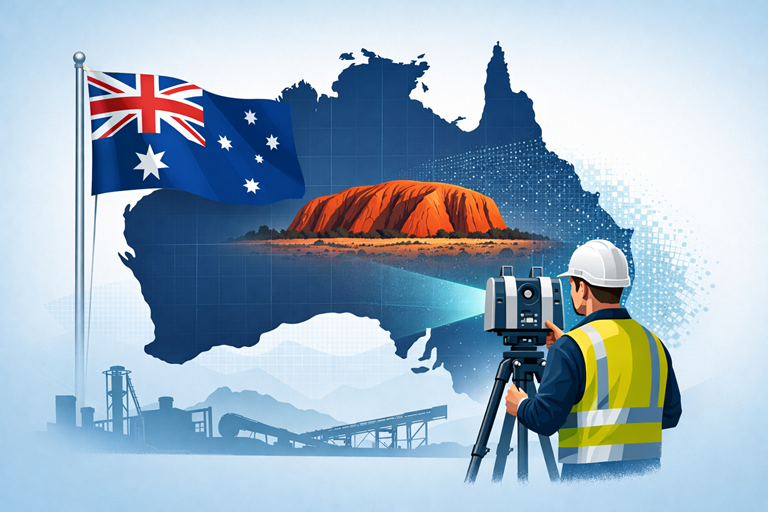
Services are available throughout Sydney, Newcastle, the Hunter Valley, regional Live NSW and across Australia.
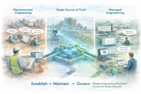
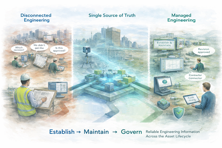
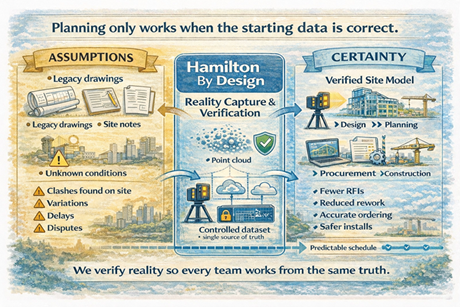
Successful Structural, Mechanical and Piping (SMP) projects are built on one fundamental principle: decisions must be based on accurate knowledge of existing conditions. In brownfields industrial environments, legacy drawings and manual measurements rarely reflect the current state of an asset. Over years of operation, piping is rerouted, structures are strengthened, and equipment is modified to meet changing production demands.
Commencing design on the basis of incomplete or inaccurate information introduces uncertainty that can affect safety, cost, schedule, and quality. Modern 3D laser scanning provides a disciplined method to remove this uncertainty and establish a reliable foundation for project delivery.
Establishing a Reliable Baseline
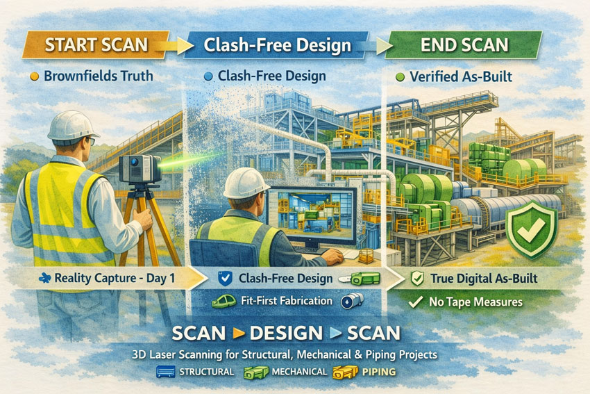
An initial 3D laser scan captures a high-resolution digital representation of the facility, recording structural elements, mechanical equipment, and piping systems exactly as they exist. This dataset becomes the authoritative reference for all subsequent engineering activities.
By beginning with a comprehensive reality capture, project teams can:
Define accurate tie-in locations for new works
Understand spatial constraints and access requirements
Identify potential clashes before detailed design
Reduce reliance on manual surveys and assumptions
Provide designers with objective, measurable data
This approach aligns engineering decisions with actual site conditions, supporting informed planning and reducing the likelihood of downstream rework.
Designing From Truth Rather Than Assumption
When the design phase is grounded in verified scan data, coordination across structural, mechanical, and piping disciplines becomes more effective. Engineers are able to develop models that reflect the real environment rather than an idealised interpretation of it.
The benefits to project success include:
Improved accuracy of fabrication documentation
Reduced design revisions and RFIs
Greater confidence in constructability
More reliable cost and schedule forecasting
Enhanced collaboration between designers, fabricators, and site teams
A scan-based workflow supports the objective of “fit-first” construction, where components are manufactured with confidence that they will integrate with existing assets.
Verifying Outcomes With a Final Scan
Project success is not only measured by installation, but by the quality of information handed to the asset owner. A second 3D scan at project completion provides a verified digital as-built of all SMP works.
This final dataset delivers:
An accurate record of installed structural, mechanical, and piping systems
Validation that construction matches design intent
A foundation for maintenance and asset management
Reliable data for future modifications or expansions
Elimination of manual tape-based as-built surveys
The organisation is left with a living digital asset rather than static drawings that quickly lose relevance.
Supporting Measurable Project Outcomes
Adopting a Scan → Design → Scan methodology directly contributes to recognised measures of project success:
Safety: Reduced site rework and unplanned interventions
Cost Control: Fewer field modifications and claims
Schedule Reliability: Shorter shutdowns and predictable installation
Quality: Higher confidence in alignment and tolerances
Knowledge Retention: Creation of enduring digital records
These outcomes are particularly critical in SMP environments where interfaces between steel, equipment, and piping are complex and tolerances are unforgiving.
Applications Across Industrial Sectors
This workflow is suited to a wide range of SMP activities, including:
Conveyor and materials handling upgrades
Plant expansions and debottlenecking
Tank, hopper and bin modifications
Piping reroutes and tie-ins
Shutdown and turnaround works
Brownfields engineering studies
In each case, accurate spatial data enables better engineering judgement and more predictable project delivery.
A Framework for Sustainable Project Success
For organisations seeking consistent performance from SMP projects, the integration of 3D laser scanning is not a survey exercise—it is a strategic project control measure. By capturing reality at project commencement and verifying it at completion, stakeholders gain confidence that engineering decisions, construction outcomes, and asset records are aligned.
Start with verified data. Design with confidence. Finish with a true digital as-built.
Hamilton By Design Co. partners with project teams to implement this approach, supporting safer, more reliable, and more successful SMP outcomes.
Mobile 3D Scanning Services | Onsite LiDAR for Regional Australia
When a project is outside the major cities, access to accurate engineering data can be the difference between a smooth upgrade and an expensive mistake. Mobile 3D scanning services bring high-accuracy LiDAR and reality capture directly to your site—whether that’s a regional workshop, a mine in the outback, a water treatment plant, or a small manufacturing facility in a local town.
At Hamilton By Design, our approach is simple: we come to you, capture the site as it really exists, and convert that data into build-ready CAD and point clouds that engineers, fabricators, and asset owners can rely on.
What Are Mobile 3D Scanning Services?
Mobile 3D scanning means deploying professional laser scanners and engineering workflows on location, not in a lab or office. Instead of measuring with tape, sketches, and guesswork, we capture millions of precise points that represent:
Structural steel and concrete
Pipework and mechanical equipment
Conveyor systems and bulk handling plant
Buildings, workshops, and brownfield sites
Vehicles, tanks, and custom machinery
The result is a digital twin of your asset that can be used for design, fabrication, clash detection, and maintenance planning—without repeated site visits.
Perfect for Smaller Towns and Regional Projects
Regional businesses often face the same challenges:
Limited access to specialist surveyors
Old drawings that don’t match reality
Upgrades carried out over decades
Shutdown windows that are tight and costly
Our mobile service is designed for these exact conditions. We regularly travel to local towns, industrial hubs, and remote facilities to provide the same level of engineering capture normally reserved for major city projects.
Whether you’re in the Central Coast, Mount Isa, Broken Hill, Bathurst, Rockhampton, or anywhere in between, we can mobilise quickly and deliver professional data without the need for you to bring contractors from multiple companies.
How the Process Works
1. One Day Onsite – Minimal Disruption
Most projects can be captured in a single day. We position the scanner, record high-resolution point clouds, and focus extra detail around critical tie-in points.
2. Registered Point Cloud
Back in the office we register and clean the data into a single accurate model referenced to real-world coordinates.
3. Engineering Deliverables
From that scan we can provide:
Registered point cloud files
PDF site layouts
AutoCAD / SOLIDWORKS models
Fabrication drawings
Clash and tolerance checks
Because we are engineers first—not just surveyors—the outputs are created with practical fabrication and construction in mind.
Why Mobile Scanning Beats Traditional Measuring
✔ No more hand sketches that don’t fit
✔ Reduce rework during shutdowns
✔ Design directly to existing conditions
✔ Accurate tie-ins for conveyors, elevators, pipework
✔ Evidence for compliance and asset records
✔ Faster quoting for fabricators
For small towns where every hour counts and access is limited, this approach removes uncertainty before a single piece of steel is cut.
Industries We Support
Our mobile 3D scanning services are commonly used for:
CHPP and mining upgrades
Local manufacturing plants
Food and beverage facilities
Water and wastewater sites
Sawmills and timber processing
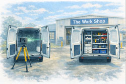
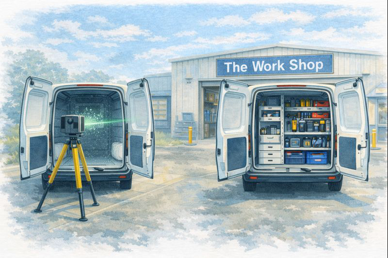
Vehicle and van fit-outs
Heritage and retrofit projects
Conveyor and bucket elevator installations
No site is too small—if it needs to fit first time, scanning makes sense.
Book Early – Our Calendar Fills Fast
Regional shutdowns and plant upgrades often happen at the same time of year. Booking early ensures:
Availability when your site is ready
Data delivered before design deadlines
Your project stays on track
We typically work on a 50% deposit with purchase order and balance on delivery of the registered point cloud and agreed outputs.
Let’s Capture Your Site – Wherever It Is
If you’re planning an upgrade in a smaller town or regional facility, talk to a team that understands both engineering and scanning.
Call Hamilton By Design www.hamiltonbydesign.com.au 📍 Servicing Sydney, Central Coast, Bathurst, Broken Hill, Perth, Mount Isa and regional Australia
Mobile 3D scanning services—bringing city-level engineering to every local town.
Fitters’ vans – precision tools, parts, and fast access
Boilermakers’ vans – heavy tools, welding gear, safe load distribution
Delivery vans – optimised load space and restraint systems
HVAC / air conditioning vans – gas bottles, units, tools
Painters / decorators – organised storage for finishes and equipment
Locksmiths / security installers – fast access, clean layout
Handymen / general maintenance – flexibility and adaptability
Camper vans – beds, storage, kitchens, and utilities that actually fit
Different trades. Same problem. One-size-fits-all doesn’t work.
Design It Right — Before It’s Built
With a 3D scan, the design team can:
trial different layouts digitally
adjust storage heights and access
confirm everything fits before fabrication
Traditionally, we assist with fit-out design — but scanning takes it further by giving everyone accurate data to work from.
This reduces:
rework
compromises
frustration
You’re Paying for a Fit-Out — Get What You Want
A van fit-out is an investment.
So ask yourself:
Why accept a generic layout?
Why compromise on access or storage?
Why redesign later when you can get it right first time?
Scan the van. Design it properly. Build it once.
The Bottom Line
Customising your van is just like customising your toolbox.
The better it suits you, the faster you work, the easier your days are, and the more value you get from it.
If you’re already spending money on a fit-out, 3D scanning your van is the smartest way to make sure you get exactly what you want — not what happens to fit.
Fabrication Integrated Modelling (FIM): Why It’s the Future for Local Fabricators
Why It Is the Future for Local Fabricators
The fabrication industry is undergoing a fundamental transformation. Increasing project complexity, tighter tolerances, compressed schedules, labour shortages, and rising material costs are placing unprecedented pressure on fabricators — particularly local workshops operating in competitive markets. At the same time, clients are demanding greater certainty: certainty of fit, certainty of schedule, and certainty of cost.
Traditional fabrication workflows, built around 2D drawings and manual interpretation, are no longer sufficient to meet these expectations. They rely heavily on experience, assumptions, and rework — all of which introduce risk. In this environment, Fabrication Integrated Modelling (FIM) is emerging not as a luxury, but as a necessity.
FIM represents a shift from drawing-based fabrication to model-driven fabrication, where a single, coordinated digital model governs design intent, fabrication detailing, procurement, machining, assembly, and installation. For local fabricators, this shift offers a path to higher productivity, improved margins, and long-term relevance in an evolving industry.
What Is Fabrication Integrated Modelling (FIM)?
Fabrication Integrated Modelling is a methodology where the fabrication model becomes the primary source of truth across the entire project lifecycle. Instead of treating design, drafting, fabrication, and installation as disconnected stages, FIM integrates them into a continuous digital workflow.
In an FIM environment:
Engineering intent is embedded directly into the model
Fabrication constraints are considered from the outset
Quantities, tolerances, and interfaces are defined digitally
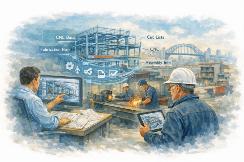
Fabrication data flows directly to machines and shop documentation
Installation sequencing is validated before material is cut
The model is not merely a visual aid — it is a fully informed digital prototype of the fabricated asset.
From Drawings to Data: A Fundamental Shift
Historically, fabrication has relied on 2D drawings as the primary communication tool. These drawings require interpretation by drafters, trades, and supervisors, each introducing assumptions based on experience and context. While this approach has worked for decades, it becomes increasingly fragile as projects grow more complex.
Fabrication Integrated Modelling replaces interpretation with explicit data. Hole locations, weld preparations, connection details, clearances, and tolerances are all defined within the model. This reduces ambiguity and ensures that everyone — from estimator to machine operator — is working from the same information.
The result is a dramatic reduction in errors, clarifications, and rework.
Why FIM Is Gaining Momentum Now
Several industry pressures are accelerating the adoption of FIM:
Increasing complexity of industrial and infrastructure projects
Reduced tolerance for errors during shutdowns and brownfield upgrades
Labour shortages and loss of experienced trades
Higher expectations for schedule and cost certainty
Growing integration of CNC and automated fabrication equipment
FIM addresses these challenges by improving coordination, predictability, and efficiency at the source — before fabrication begins.
Key Benefits of Fabrication Integrated Modelling
Reduced Errors and Rework
Rework is one of the most significant drains on fabrication profitability. Errors discovered on the workshop floor or during installation often result in cascading impacts: delays, additional labour, material waste, and strained relationships with clients.
By resolving interfaces, clashes, and tolerances digitally, FIM enables fabricators to identify and eliminate issues before steel is cut. Assemblies are tested virtually, connections are validated, and fit-up risks are significantly reduced.
This proactive approach shifts problem-solving upstream, where changes are faster, cheaper, and less disruptive.
Improved Fabrication Efficiency and Throughput
Fabrication speed is not achieved by rushing work — it is achieved by removing uncertainty. FIM provides clarity on what needs to be fabricated, in what order, and to what tolerance.
Benefits include:
Clear fabrication sequencing
Reduced downtime waiting for clarifications
Better planning of labour and machine utilisation
More predictable workshop flow
Local fabricators using FIM often report smoother operations, fewer interruptions, and a higher percentage of “right-first-time” components.
Better Use of Skilled Labour
Skilled trades are becoming harder to find and retain. Fabrication Integrated Modelling helps maximise the value of skilled workers by giving them better information, not more guesswork.
Fitters receive assemblies that align as expected. Welders focus on quality rather than correcting geometry. Supervisors make decisions based on accurate model data rather than assumptions. Apprentices gain clarity and confidence by working from model-based instructions.
Rather than replacing experience, FIM captures and amplifies it.
Seamless Integration with CNC and Fabrication Equipment
One of the strongest advantages of FIM is its ability to connect directly with modern fabrication equipment. The same model used for coordination and verification can generate machine-ready data, including:
NC files for beam lines and plate processors
Cut lists and nesting data
Part numbers and assembly marks
Machining references
This eliminates duplication of effort and reduces the risk of transcription errors. It also shortens the time between design approval and fabrication start, improving responsiveness to project changes.
Competitive Advantage for Local Fabricators
Local fabricators often compete with offshore suppliers on price alone — a contest that is difficult to win. FIM allows local workshops to compete on value rather than cost.
Key differentiators enabled by FIM include:
Faster response to changes
Higher confidence in fit-up for complex or brownfield sites
Reduced installation risk
Stronger collaboration with engineers and constructors
When site conditions change — as they inevitably do — local fabricators using FIM can adapt quickly, update models, and deliver revised components without significant disruption. This agility is a powerful advantage over remote fabrication alternatives.
FIM in Brownfield and Upgrade Projects
Brownfield projects present some of the greatest challenges in fabrication. Existing assets rarely match legacy drawings, and tolerances are often tight. Discovering misalignment during installation can result in costly delays and extended shutdowns.
Fabrication Integrated Modelling, often combined with accurate site capture, allows fabricators to design and fabricate components that align with actual site conditions rather than assumptions.
This approach reduces:
On-site modifications
Temporary works
Installation delays
Safety risks associated with forced fit-ups
For local fabricators servicing industrial plants and operational facilities, FIM is rapidly becoming an expected capability.
Financial Benefits: Protecting Margins, Not Just Schedules
While FIM is often associated with speed and accuracy, its most important benefit may be margin protection.
Model-based workflows enable:
More accurate pricing through reliable quantities
Reduced contingency allowances
Predictable labour and machine hours
Lower material waste
Fewer disputes and variations
By increasing certainty, FIM allows fabricators to price work confidently rather than defensively. Over time, this leads to healthier margins and more sustainable operations.
Earlier Engagement and Better Project Outcomes
Fabricators who adopt FIM often find themselves involved earlier in projects. Engineers and asset owners increasingly recognise the value of fabrication input during design development.
Early collaboration enables:
Design for manufacture and assembly
Smarter connection strategies
Reduced installation complexity
Improved safety outcomes
This shifts the fabricator’s role from reactive supplier to active project partner, strengthening relationships and improving project outcomes for all parties.
Overcoming Barriers to Adoption
Adopting Fabrication Integrated Modelling requires investment — not only in software and systems, but in people and processes. Common challenges include:
Training requirements
Changes to established workflows
Initial productivity adjustments
Cultural resistance to new methods
Successful fabricators address these challenges incrementally. They start with pilot projects, focus on repeatable wins, and work closely with engineering and modelling partners to build capability over time.
The risk of maintaining outdated workflows is increasingly greater than the risk of change.
The Future of Fabrication: Integrated Digital Ecosystems
FIM is not the final destination — it is the foundation for a more connected fabrication industry. As digital maturity increases, fabrication models will increasingly link to:
Digital twins
Quality assurance records
Traceability and compliance systems
Asset management platforms
Automated inspection and verification
In this future, the fabrication model becomes a long-term asset, supporting not only construction but operation and maintenance.
Why Fabrication Integrated Modelling Is the Future for Local Fabricators
Local fabrication is not disappearing — it is evolving. Workshops that continue to rely solely on 2D drawings and manual processes will face increasing pressure from cost, risk, and competition. Those that embrace Fabrication Integrated Modelling will position themselves for long-term success.
By adopting FIM, local fabricators can:
Deliver higher quality with greater confidence
Reduce rework and wasted effort
Protect margins in competitive markets
Strengthen relationships with engineers and clients
Build resilient, future-ready businesses
Fabrication Integrated Modelling is not about replacing trades or experience. It is about supporting them with better information, clearer intent, and integrated workflows.
For local fabricators willing to invest in capability and collaboration, FIM is not just the future — it is the pathway to remaining relevant, competitive, and profitable in an increasingly digital industry.
To provide the best experiences, we use technologies like cookies to store and/or access device information. Consenting to these technologies will allow us to process data such as browsing behaviour or unique IDs on this site. Not consenting or withdrawing consent, may adversely affect certain features and functions.
Functional
Always active
The technical storage or access is strictly necessary for the legitimate purpose of enabling the use of a specific service explicitly requested by the subscriber or user, or for the sole purpose of carrying out the transmission of a communication over an electronic communications network.
Preferences
The technical storage or access is necessary for the legitimate purpose of storing preferences that are not requested by the subscriber or user.
Statistics
The technical storage or access that is used exclusively for statistical purposes.The technical storage or access that is used exclusively for anonymous statistical purposes. Without a subpoena, voluntary compliance on the part of your Internet Service Provider, or additional records from a third party, information stored or retrieved for this purpose alone cannot usually be used to identify you.
Marketing
The technical storage or access is required to create user profiles to send advertising, or to track the user on a website or across several websites for similar marketing purposes.