Identifying Fastener Threads in the Field

Metric vs American vs British Threads โ€” and the Australian Standards That Govern Them

In maintenance workshops and brownfield sites, one of the most common hidden problems is not bolt strength โ€” it is thread identification.

Equipment imported from the USA, Europe and the UK often ends up assembled together on Australian sites.
The bolts may look identical.
They may even screw together.

But they are not interchangeable.

Incorrect thread matching damages load capacity, prevents correct preload, and leads to loosening, fatigue cracking and eventual failure.

This guide explains the major fastening thread systems encountered in Australia (excluding pipe threads), how to recognise them, and the Australian Standards that apply.


1. The Three Fastener Thread Systems

There are three main fastening thread families encountered in mechanical and structural equipment:

SystemOriginThread AngleTypical Location
Metric ISOAustralia / Europe / modern equipment60ยฐMost modern machinery
Unified (UNC/UNF)USA60ยฐMining & imported plant
Whitworth (BSW/BSF/BA)UK / older Commonwealth55ยฐOlder equipment & legacy machinery

Even though UNC and Metric share a 60ยฐ angle, the pitch is different โ€” therefore they are not compatible.

Whitworth threads are particularly problematic because they will partially screw into metric or UNC holes before binding.


2. Metric Threads (ISO Metric โ€” Australian Standard Fasteners)

These are the primary fastening threads used in Australia.

(Coarse pitch series)

SizeMajor DiameterPitchMinor Diameter (approx)
M66.0 mm1.04.8 mm
M88.0 mm1.256.5 mm
M1010.0 mm1.58.2 mm
M1212.0 mm1.759.9 mm
M1616.0 mm2.013.8 mm
M2020.0 mm2.517.3 mm
M2424.0 mm3.020.8 mm

Fine pitch versions also exist for vibration and adjustment applications.

Typical Uses

  • Structural steel connections
  • Machinery assembly
  • Guards and access platforms
  • General engineering

3. Unified American Threads (UNC / UNF)

Common on imported mining and mobile equipment.

UNC โ€“ Coarse

SizeMajor DiameterPitch
1/4-206.35 mm1.27 mm
3/8-169.53 mm1.59 mm
1/2-1312.70 mm1.95 mm
3/4-1019.05 mm2.54 mm
1-825.40 mm3.18 mm

UNF โ€“ Fine

Used where vibration resistance is required.

Key Characteristic
UNC bolts will often start threading into metric holes but will not achieve correct preload.


4. British Threads (Whitworth Form)

Recognised by their 55ยฐ thread angle.

BSW โ€“ Coarse

SizeMajor DiameterPitch
1/4 BSW6.35 mm1.34 mm
3/8 BSW9.53 mm1.59 mm
1/2 BSW12.70 mm2.12 mm
3/4 BSW19.05 mm2.54 mm

BSF โ€“ Fine

Used historically in machinery.

BA Threads

Small instrumentation and electrical fasteners.

Typical Location

  • Pre-1980 plant
  • UK imported machinery
  • Electrical equipment

Why Incorrect Thread Matching Causes Failures

Threads do not primarily carry shear load โ€” they generate preload.

If pitch or angle differs:

  • preload is reduced
  • flank contact is uneven
  • joint loosens under vibration
  • fatigue cracking begins

Many failures blamed on vibration are actually incorrect thread engagement.


Field Identification Tips

ObservationLikely Thread
Marked M12Metric
Fraction size (1/2, 3/4)UNC/UNF or Whitworth
Smooth but tight engagementWrong pitch
Binds after 2 turnsWhitworth vs Metric

Thread gauge confirmation is always recommended.


Australian Standards Relating to Fastener Threads

Metric Thread Geometry

AS 1721 โ€” General purpose metric screw threads
AS 1275 โ€” Metric screw threads for fasteners

Fastener Product Standards

AS 1110 โ€” Metric hex bolts and screws
AS 1111 โ€” Commercial hex bolts and screws
AS 1112 โ€” Hexagon nuts
AS 1420 โ€” Socket head cap screws

Mechanical Properties

AS/NZS 4291.1 โ€” Mechanical properties of bolts, screws and studs
AS/NZS 4291.2 โ€” Mechanical properties of nuts
ISO 898-1 / ISO 898-2 โ€” Adopted strength properties
ISO 3506 โ€” Stainless steel fasteners

Structural Bolting

AS/NZS 1252 โ€” High strength structural bolting assemblies
AS 4100 โ€” Steel structures design
AS/NZS 5131 โ€” Fabrication and erection of structural steel

Coatings and Fit Allowances

AS/NZS 1214 โ€” Galvanised coatings on threaded fasteners
AS/NZS 4680 โ€” Hot dip galvanising
AS 2312.2 โ€” Corrosion protection guide
AS 1897 โ€” Electroplated coatings
3D LiDAR scanning and 3D modelling service button โ€” laser scanner capturing a point cloud for engineering and CAD modelling
Mechanical engineering services
Name
Would you like us to arrange a phone consultation for you?
Address

3D CAD Modelling Australia service banner for Hamilton By Design
3D LiDAR scanning and 3D modelling service button โ€” laser scanner capturing a point cloud for engineering and CAD modelling
Mechanical engineering services
Mechanical drafting services button
Blue rounded button with the text โ€œSolidWorks Designโ€ in white.
Blue banner graphic displaying the text "Point Cloud to CAD - Australia" in large white lettering, representing point cloud processing, scan-to-CAD conversion and digital engineering services across Australia.
Mechanical, Structural & Pipework Drafting service banner by Hamilton By Design featuring white text on a blue background.
Engineering Governance title graphic featuring bold white text reading "Engineering Governance" centred on a blue rounded rectangle background.
Mining Plant Upgrades promotional graphic with bold white text on a blue background representing mining infrastructure, plant improvement, and engineering upgrade projects.
3D Pipework promotional graphic with bold white text on a blue background representing pipework design, modelling, drafting, and engineering services.
Australian Drafting logo featuring bold white text reading "Australian Drafting" centred on a blue rounded rectangle background.
3D Pipework promotional graphic with bold white text on a blue background representing pipework design, modelling, drafting, and engineering services.
Mining Plant Upgrades promotional graphic with bold white text on a blue background representing mining infrastructure, plant improvement, and engineering upgrade projects.
3D LiDAR Scanning for Engineering Projects title graphic featuring bold white text on a blue rounded rectangle background.
Australian Drafting logo featuring bold white text reading "Australian Drafting" centred on a blue rounded rectangle background.
Engineering Governance title graphic featuring bold white text reading "Engineering Governance" centred on a blue rounded rectangle background.
Mechanical, Structural & Pipework Drafting service banner by Hamilton By Design featuring white text on a blue background.
Mechanical engineering services
Blue rounded button with the text โ€œSolidWorks Designโ€ in white.
Finite Element Analysis (FEA) engineering simulation button

Mechanical Engineering | Structural Engineering


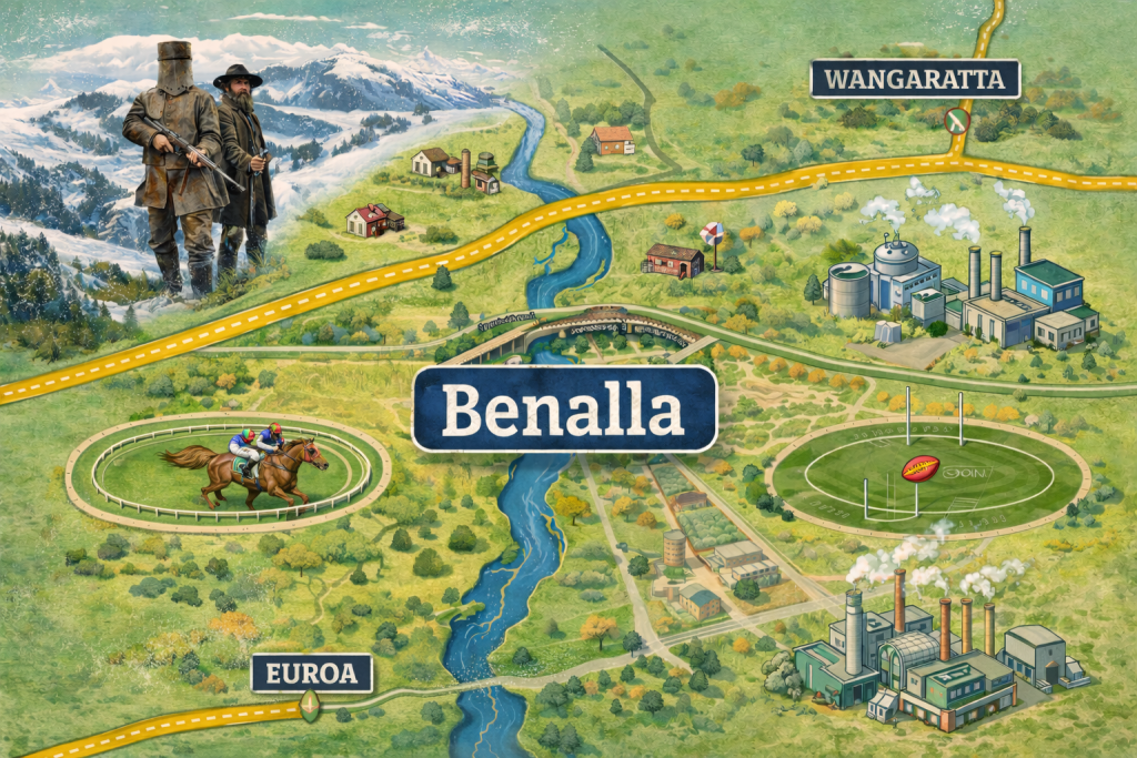
Mechanical Engineering Support for Manufacturing in Benalla

Mechanical Engineering Support Benalla | Manufacturing & Industrial

Practical engineering for real factories, real equipment, real deadlines

Benalla and the North East Victorian region are built on strong manufacturingโ€”electrical equipment, heavy industry, fabrication, food processing, and specialist production. Mechanical engineers working in these environments need support that understands uptime, safety, compliance, and getting equipment back into service quickly.

Hamilton By Design provides hands-on mechanical engineering services that help manufacturers move from site reality to engineering-ready solutionsโ€”without disrupting production.


Who we work with

We support mechanical engineers, maintenance teams, project managers, and workshop leaders across:

  • Electrical and industrial equipment manufacturing
  • Process and production facilities
  • Fabrication workshops and OEM suppliers
  • Maintenance and reliability teams
  • Capital upgrade and shutdown projects

Our role is to strengthen your in-house capability with accurate site information, practical design support, and clear engineering deliverables.


Our services

Site verification & as-built capture

Decisions are only as good as the information behind them. We help confirm existing conditions before designs are locked in.

  • Existing plant and equipment verification
  • Field measurement and dimensional checks
  • Brownfield interface confirmation
  • Layout validation before fabrication

3D laser scanning for manufacturing sites

Modern manufacturing upgrades demand accurate spatial data. We capture and deliver point clouds tailored for engineering workflows.

  • Rapid on-site data capture
  • Registered point cloud deliverables
  • Support for upgrades, relocations, and new equipment installs
  • Clash identification before shutdowns

Mechanical layout & modification support

Practical engineering to make changes fit the real world.

  • Equipment arrangement and access reviews
  • Interface coordination with structures and services
  • Design checks against site constraints
  • Fabrication and installation support

Reliability & maintenance engineering

Helping teams reduce downtime and improve maintainability.

  • Maintenance access optimisation
  • Equipment changeover planning
  • Practical improvement recommendations
  • Support for maintenance documentation

Manufacturing documentation

Clear, structured information that workshop and site teams can actually use.

  • Engineering-ready drawing packages
  • Asset and modification records
  • Handover documentation
  • Fabrication support information

Why manufacturing teams choose us

  • Engineer-led, site-first approach โ€“ we design around how your plant really operates
  • Production-aware โ€“ focused on minimal disruption and practical outcomes
  • Cross-discipline thinking โ€“ mechanical, structural and fabrication interfaces
  • Deliverables that work on the workshop floor โ€“ not just in the office

Typical projects in Benalla

  • Equipment upgrades and replacements
  • New machine installations into existing lines
  • Factory relocations and layout changes
  • Shutdown measurement and documentation
  • Access and maintainability improvements
  • Reverse engineering of legacy equipment

How we engage

  1. Initial discussion โ€“ understand your equipment, constraints, and timeline
  2. Plan the site approach โ€“ access, safety, and production considerations
  3. On-site capture & verification
  4. Delivery of practical engineering outputs ready for your workflow

Hamilton By Design logo displayed on a blue tilted rectangle with a grey gradient background

Contact

If youโ€™re a mechanical engineer or manufacturer in Benalla needing practical engineering support, we can help bridge the gap between site and design.

Hamilton By Design Co.
Servicing Benalla & Northeast Victoria

3D LiDAR scanning and 3D modelling service button โ€” laser scanner capturing a point cloud for engineering and CAD modelling
Mechanical engineering services


Name
Would you like us to arrange a phone consultation for you?
Address
3D CAD Modelling Australia service banner for Hamilton By Design

3D Engineering Scanning in Fiji โ€“ Reliable Point Clouds for Global Engineering

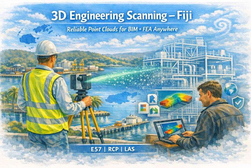
Engineer performing 3D laser scanning in Fiji with point cloud transforming into BIM model and FEA analysis beside a tropical port.

3D Engineering Scanning Fiji โ€“ Point Clouds for Design & FEA | Hamilton By Design

Hamilton By Design provides professional 3D laser scanning services across Fiji, delivering high-accuracy point clouds that allow designers, engineers, and asset owners anywhere in the world to work with real, measured dataโ€”without stepping foot on site.

Our focus is simple:
capture the truth of your asset once, and let every engineering discipline design from the same digital backbone.


Engineering-Grade Data You Can Design From

In Fiji, many industrial, marine, and commercial assets have:

  • incomplete or outdated drawings

  • decades of informal modifications
  • mixed construction standards
  • corrosion and cyclone damage history

Traditional measurement methods struggle in this environment. Our 3D scanning service produces a survey-accurate digital replica that can be used for:

  • 3D modelling in Revit, Plant3D, Tekla, SolidWorks
  • structural analysis and FEA studies
  • clash detection for new equipment
  • fabrication of steel and pipework
  • condition assessments and deformation checks

We deliver neutral, open formats so your teamโ€”anywhere in Australia, New Zealand, Fiji, or globallyโ€”can immediately begin engineering work.


What We Deliver

Core Outputs

  • Registered point clouds (E57 / RCP / LAS)
  • Colourised, engineering-accurate datasets
  • Site coordinate systems or project datum
  • Mesh models for Navisworks / visualisation
  • 2D plans, elevations, and sections

Optional Engineering Deliverables

  • Scan-to-BIM models (LOD 200โ€“350)
  • Steel and pipe geometry extraction
  • Tie-in coordinates for brownfields projects
  • Deformation and roundness reports
  • Clash and constructability reviews

Every dataset is processed in Australia under formal QA procedures so it can be relied upon for detailed design, certification, and FEA modelling.


Designed for Fiji Conditions

Scanning in Fiji requires more than equipmentโ€”it requires experience in Pacific environments.

We plan projects around:

  • tropical heat and humidity
  • sudden rain events
  • reflective stainless and bright sunlight
  • inter-island logistics
  • remote power and access constraints
  • cyclone season scheduling

Our workflows are built so field capture is efficient and robust, while processing and modelling are completed by our Australian engineering team.


Industries We Support in Fiji

  • Ports and wharves โ€“ Suva, Lautoka, Levuka
  • Power generation and utilities
  • Sugar and food processing plants
  • Water and wastewater infrastructure
  • Resorts and commercial buildings

  • Bridges and civil structures
  • Post-cyclone assessments
  • Mining and materials handling

A Digital Backbone for Global Teams

A quality scan is the backbone of every downstream task.
If the backbone is wrong, every model, drawing, and FEA result is compromised.

Our aim is to give your project a foundation that:

  • removes re-measure risk
  • allows off-site fabrication
  • supports remote engineering teams
  • shortens shutdowns
  • improves safety and constructability

Designers and engineers in any location can open our data and begin work immediatelyโ€”confident it represents the real world.

3D LiDAR scanning and 3D modelling service button โ€” laser scanner capturing a point cloud for engineering and CAD modelling
Mechanical engineering services

Hamilton By Design logo displayed on a blue tilted rectangle with a grey gradient background

Why Choose Hamilton By Design

  • Engineer-led scanning team
  • Australian processing and QA
  • experience in PNG and Pacific brownfields
  • deliverables tailored to your software
  • practical understanding of fabrication and FEA requirements

We donโ€™t just capture pointsโ€”we deliver usable engineering information.


Talk to Us About Your Fiji Project

Whether you need a single building, a wharf, or a full processing plant captured, we can mobilise quickly and provide data your global team can trust.

Hamilton By Design
Engineering certainty through 3D scanning.

Name
Would you like us to arrange a phone consultation for you?
Address

3D CAD Modelling Australia service banner for Hamilton By Design
Finite Element Analysis (FEA) engineering simulation button
Mechanical engineering services

Industrial 3D Scanning in WA Mines & Processing

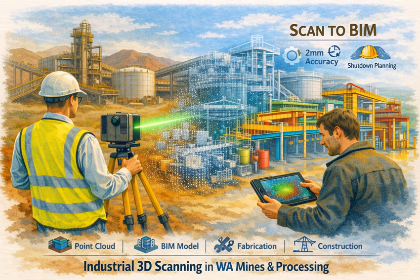
Laser scanning of WA mining infrastructure with Scan-to-BIM visualisation for industrial processing engineering.

Industrial 3D Scanning in WA Mines & Processing | Scan-to-BIM

Building Engineering Certainty in Brownfield Environments

Western Australiaโ€™s mining and mineral processing sector operates some of the most complex industrial assets in the world. Aging infrastructure, continuous production demands, and aggressive expansion schedules mean that every engineering decision must be based on accurate, reliable information. Industrial 3D Scanning in WA Mines & Processing has become the foundation for achieving this certaintyโ€”providing precise digital representations of plants, structures, and equipment before a single drawing is issued.


Industrial 3D scanning in WA mines showing laser capture of a processing plant with point cloud transforming into a BIM model.

The Backbone of Modern Mine Engineering

A laser scan is not simply a survey tool; it is the backbone of the entire project lifecycle. The quality of the initial scan determines the ease and accuracy of every task that followsโ€”layout design, clash detection, fabrication, and construction. If the backbone is broken, even simple tasks become difficult. Poor capture leads to rework, fabrication errors, and costly shutdown delays.

Industrial 3D scanning captures millions of measured points across conveyors, tanks, structural steel, pipe racks, and mechanical equipment with millimetre accuracy. For WA mine sites where access is restricted and downtime is expensive, this technology removes guesswork and replaces assumptions with verified data.


From Point Cloud to BIM Deliverables

The true value of scanning lies in what is delivered after capture. For mines and processing facilities, typical outputs include:

  • Engineering-grade point clouds for AutoCAD, Revit, and plant design platforms
  • Scan-to-BIM models of structures, pipework, and mechanical systems
  • Fabrication-ready DXF, STEP, or Parasolid files
  • Navisworks meshes for stakeholder review and constructability planning
  • As-built verification for shutdown and tie-in works

These deliverables allow engineering teams to design remotely, plan upgrades with confidence, and eliminate the need for repeated site visits across the vast distances of Western Australia.

Protecting the Project Team

Industrial projects are often pressured by schedules and budgets. High-quality 3D scanning protects the entire delivery teamโ€”project managers, engineers, designers, and fabricatorsโ€”by providing an objective source of truth. When design decisions are based on measured reality rather than tape measures and sketches, disputes reduce and collaboration improves.

For brownfield WA sites with decades of undocumented modifications, scanning becomes the neutral reference that aligns contractors, owners, and operators around the same dataset.

Applications Across WA Mines & Processing

Industrial 3D Scanning in WA Mines & Processing supports a wide range of activities:

  • Shutdown planning and tie-in verification
  • Conveyor and chute upgrades
  • Tank and structural remediation
  • Pipe spool prefabrication
  • Access platform and maintenance improvements
  • Expansion of crushing and screening circuits
  • Safety and egress compliance reviews

Whether in the Pilbara iron ore operations, Goldfields processing plants, or nickel and lithium facilities, scanning reduces risk in some of Australiaโ€™s harshest and most remote environments.

Remote Doesnโ€™t Mean Isolated

Western Australian mine sites can feel isolated, yet digital capture connects them directly to engineering teams anywhere in Australia. A single field visit can provide enough data for months of detailed design work. Teams can โ€œwalk the plantโ€ virtually, measure clearances, and develop solutions without repeated flights or shutdown interruptions.

An Engineer-Led Approach

Effective scan programs must be led by engineers who understand how the data will be used. Capture strategies, target placement, and accuracy tolerances are defined around the BIM deliverables, not around the scanner. This ensures that the final models support fabrication, not just visualisation.

3D LiDAR scanning and 3D modelling service button โ€” laser scanner capturing a point cloud for engineering and CAD modelling
Mechanical engineering services

Hamilton By Design logo displayed on a blue tilted rectangle with a grey gradient background

Industrial 3D Scanning in WA Mines & Processing is no longer optionalโ€”it is the starting point for safe, efficient, and predictable project delivery. When the backbone is strong, every downstream task becomes easier.

If your operation is planning upgrades, shutdowns, or expansions, begin with a measured digital foundation and let the data drive the outcome.

Our clients

Contact Us – Talk to Us

Name
Would you like us to arrange a phone consultation for you?
Address

Mechanical Engineering Perth WA banner for Hamilton By Design featuring white text on a blue background.
3D Laser Scanning Perth WA banner for Hamilton By Design with white text on a blue background.
SolidWorks Perth WA banner for Hamilton By Design featuring white text on a blue background.
https://www.hamiltonbydesign.com.au/perth-wa
3D CAD Modelling Australia service banner for Hamilton By Design
Mechanical Engineering Perth WA banner for Hamilton By Design featuring white text on a blue background.
3D Laser Scanning Perth WA banner for Hamilton By Design with white text on a blue background.
SolidWorks Perth WA banner for Hamilton By Design featuring white text on a blue background.
3D LiDAR scanning and 3D modelling service button โ€” laser scanner capturing a point cloud for engineering and CAD modelling
Mechanical engineering services
https://www.hamiltonbydesign.com.au/perth-wa

3D CAD Modelling Australia service banner for Hamilton By Design


CHPP Engineering title graphic featuring bold white text reading "CHPP Engineering" centred on a blue rounded rectangle background.
Pipework Drafting title graphic featuring bold white text reading "Pipework Drafting" centred on a blue rounded rectangle background.
3D LiDAR Scanning for Engineering Projects title graphic featuring bold white text on a blue rounded rectangle background.


Finite Element Analysis (FEA) engineering simulation button
Structural drafting services button
Mechanical drafting services button


Australian Drafting logo featuring bold white text reading "Australian Drafting" centred on a blue rounded rectangle background.
Engineering Governance title graphic featuring bold white text reading "Engineering Governance" centred on a blue rounded rectangle background.
Engineering-Grade LiDAR Scanning title graphic featuring bold white text on a blue rounded rectangle background.


Mechanical drafting services button
Structural drafting services button


Fabrication and product design services
3D CAD Modelling Australia service banner for Hamilton By Design
Mechanical, Structural & Pipework Drafting service banner by Hamilton By Design featuring white text on a blue background.


3D LiDAR scanning and 3D modelling service button โ€” laser scanner capturing a point cloud for engineering and CAD modelling
Mechanical engineering services
Mining & Processing Perth WA banner for Hamilton By Design featuring white text on a blue background.
Scan to BIM Perth WA banner for Hamilton By Design featuring white text on a blue background.
Ship Building Perth WA banner for Hamilton By Design featuring white text on a blue background.
Structural drafting services button
3D LiDAR scanning and 3D modelling services button
Mechanical drafting services button

SMP Projects: Enabling Project Success Through a Scan โ†’ Design โ†’ Scan Workflow

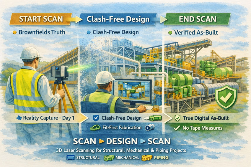
Watercolour-style illustration showing SMP 3D laser scanning workflow from start capture to clash-free design and final digital as-built.

Successful Structural, Mechanical and Piping (SMP) projects are built on one fundamental principle: decisions must be based on accurate knowledge of existing conditions. In brownfields industrial environments, legacy drawings and manual measurements rarely reflect the current state of an asset. Over years of operation, piping is rerouted, structures are strengthened, and equipment is modified to meet changing production demands.


Commencing design on the basis of incomplete or inaccurate information introduces uncertainty that can affect safety, cost, schedule, and quality. Modern 3D laser scanning provides a disciplined method to remove this uncertainty and establish a reliable foundation for project delivery.


Establishing a Reliable Baseline

An initial 3D laser scan captures a high-resolution digital representation of the facility, recording structural elements, mechanical equipment, and piping systems exactly as they exist. This dataset becomes the authoritative reference for all subsequent engineering activities.

By beginning with a comprehensive reality capture, project teams can:

  • Define accurate tie-in locations for new works
  • Understand spatial constraints and access requirements
  • Identify potential clashes before detailed design
  • Reduce reliance on manual surveys and assumptions
  • Provide designers with objective, measurable data

This approach aligns engineering decisions with actual site conditions, supporting informed planning and reducing the likelihood of downstream rework.


SMP scanโ€“designโ€“scan process illustrated with laser scanner, point cloud model and finished industrial plant.

Designing From Truth Rather Than Assumption

When the design phase is grounded in verified scan data, coordination across structural, mechanical, and piping disciplines becomes more effective. Engineers are able to develop models that reflect the real environment rather than an idealised interpretation of it.

The benefits to project success include:

  • Improved accuracy of fabrication documentation
  • Reduced design revisions and RFIs
  • Greater confidence in constructability
  • More reliable cost and schedule forecasting
  • Enhanced collaboration between designers, fabricators, and site teams

A scan-based workflow supports the objective of โ€œfit-firstโ€ construction, where components are manufactured with confidence that they will integrate with existing assets.


Verifying Outcomes With a Final Scan

Project success is not only measured by installation, but by the quality of information handed to the asset owner. A second 3D scan at project completion provides a verified digital as-built of all SMP works.

This final dataset delivers:

  • An accurate record of installed structural, mechanical, and piping systems
  • Validation that construction matches design intent
  • A foundation for maintenance and asset management
  • Reliable data for future modifications or expansions
  • Elimination of manual tape-based as-built surveys

The organisation is left with a living digital asset rather than static drawings that quickly lose relevance.


Supporting Measurable Project Outcomes

Adopting a Scan โ†’ Design โ†’ Scan methodology directly contributes to recognised measures of project success:

  • Safety: Reduced site rework and unplanned interventions
  • Cost Control: Fewer field modifications and claims
  • Schedule Reliability: Shorter shutdowns and predictable installation
  • Quality: Higher confidence in alignment and tolerances
  • Knowledge Retention: Creation of enduring digital records

These outcomes are particularly critical in SMP environments where interfaces between steel, equipment, and piping are complex and tolerances are unforgiving.


Applications Across Industrial Sectors

This workflow is suited to a wide range of SMP activities, including:

  • Conveyor and materials handling upgrades
  • Plant expansions and debottlenecking
  • Tank, hopper and bin modifications
  • Piping reroutes and tie-ins
  • Shutdown and turnaround works
  • Brownfields engineering studies

In each case, accurate spatial data enables better engineering judgement and more predictable project delivery.

3D LiDAR scanning and 3D modelling service button โ€” laser scanner capturing a point cloud for engineering and CAD modelling
Mechanical engineering services

Hamilton By Design logo displayed on a blue tilted rectangle with a grey gradient background

A Framework for Sustainable Project Success

For organisations seeking consistent performance from SMP projects, the integration of 3D laser scanning is not a survey exerciseโ€”it is a strategic project control measure. By capturing reality at project commencement and verifying it at completion, stakeholders gain confidence that engineering decisions, construction outcomes, and asset records are aligned.

Start with verified data.
Design with confidence.
Finish with a true digital as-built.

Hamilton By Design Co. partners with project teams to implement this approach, supporting safer, more reliable, and more successful SMP outcomes.

Name
Would you like us to arrange a phone consultation for you?
Address

Finite Element Analysis (FEA) engineering simulation button
Mechanical engineering services

3D Laser Scanning in New Caledonia โ€“ Engineering Certainty in a Remote Environment

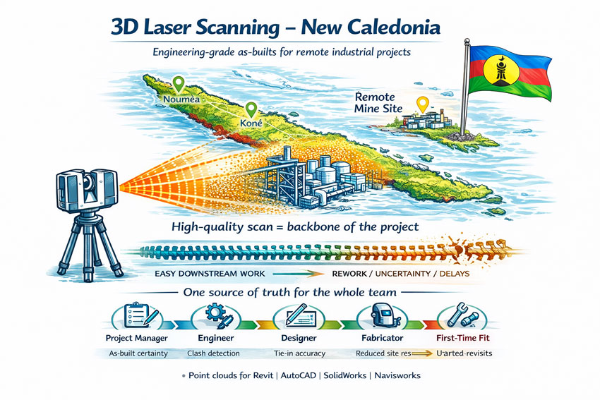
Illustration of 3D laser scanning in New Caledonia showing a LiDAR scanner capturing an industrial site over a coloured map with the Kanak flag and point cloud overlay.

3D Laser Scanning New Caledonia | Hamilton By Design

Engineering projects in New Caledonia operate in a unique environment. Nickel processing plants, port facilities, power stations and infrastructure are often decades old, heavily modified and located far from design offices. Accurate site information is the difference between a smooth project and an expensive lesson.

3D laser scanning has become the most reliable way to capture existing conditions across Noumรฉa, Konรฉ and the remote mine sites of the Grande Terre. Instead of relying on tape measures and assumptions, LiDAR technology records millions of precise measurements to create a true digital twin of the asset.


The Challenge of Brownfields Projects in New Caledonia

Many facilities in New Caledonia share the same constraints:

  • Limited shutdown windows
  • Corrosive coastal environments
  • Historical modifications with poor drawings
  • Logistics that make repeat site visits costly
  • Multi-discipline coordination between local and overseas teams

Traditional survey methods struggle to capture congested pipe racks, structural steel distortions or equipment that has shifted over time. When drawings do not match reality, fabrication delays and site rework quickly follow.


3D laser scanning New Caledonia graphic with national colours, flag on map, industrial facility and workflow from scan to first-time fit.

The Scan Is the Backbone of the Project

The initial scan quality sets the tone for every task that follows. The point cloud becomes the backbone of the projectโ€”design, detailing, fabrication and construction all rely on it.

If you start with a broken backbone, you will have problems everywhere else:

  • Simple tasks become difficult
  • Measurements are questioned
  • models need rework
  • fabricators lose confidence
  • schedules start to slip

A clean, well-registered scan makes coordination easy. A poor scan multiplies effort for every member of the team.


Protecting the Whole Project Team

3D laser scanning is not just about creating a modelโ€”it is about protecting everyone involved:

  • Project managers who must control time and cost
  • Engineers responsible for safe and compliant designs
  • Designers and draftspersons who need reliable geometry
  • Fabricators who must build components that fit
  • Construction crews who install the work on short shutdowns

When the as-built data is right, the entire chain works with confidence. When it is wrong, every discipline inherits the problem.


How 3D Laser Scanning Changes the Outcome

A terrestrial laser scanner captures a complete point cloud of the site in hours rather than weeks. The data can then be used for:

  • Accurate as-built models for upgrades and expansions
  • Tie-in design for new conveyors, tanks and platforms
  • Structural verification of aging infrastructure
  • Clash detection before fabrication
  • Shutdown planning and risk reduction
  • Asset documentation for long-term maintenance

For New Caledonian projects, the biggest benefit is capture once, design anywhere. Local scanning crews can collect the data while engineering teams in Australia or New Zealand work from the same digital environment without further travel.


Typical Applications Across New Caledonia

Mining & Processing

  • Nickel plant upgrades
  • Conveyor replacements
  • Chute and transfer redesign
  • Tank and thickener modifications
  • Access platforms and walkways

Ports & Infrastructure

  • Wharf structural assessments
  • Ship loader interfaces
  • Pipe bridges and services
  • Electrical and control building upgrades

Energy & Utilities

  • Power station retrofits
  • Water treatment facilities
  • Fuel storage terminals

From Point Cloud to Deliverables

A professional workflow generally includes:

  1. On-site LiDAR capture with survey control
  2. Registration and quality assurance
  3. Creation of usable formats for Revit, AutoCAD, SolidWorks or Navisworks
  4. Extraction of models, drawings or clash reports
  5. Ongoing support during fabrication and installation

The result is engineering data you can trustโ€”without the need for multiple trips to site.

3D LiDAR scanning and 3D modelling service button โ€” laser scanner capturing a point cloud for engineering and CAD modelling
Mechanical engineering services

Hamilton By Design logo displayed on a blue tilted rectangle with a grey gradient background

Ready to De-Risk Your Project?

Whether your project is in Noumรฉa, Konรฉ or a remote mine site, 3D laser scanning provides the foundation for safe, predictable and efficient engineering. Get the backbone right at the start and the rest of the project becomes easier.


Name
Would you like us to arrange a phone consultation for you?
Address

3D CAD Modelling Australia service banner for Hamilton By Design
3D LiDAR scanning and 3D modelling service button โ€” laser scanner capturing a point cloud for engineering and CAD modelling
Mechanical engineering services
Mechanical drafting services button
Blue rounded button with the text โ€œSolidWorks Designโ€ in white.
Blue banner graphic displaying the text "Point Cloud to CAD - Australia" in large white lettering, representing point cloud processing, scan-to-CAD conversion and digital engineering services across Australia.
Mechanical, Structural & Pipework Drafting service banner by Hamilton By Design featuring white text on a blue background.
Engineering Governance title graphic featuring bold white text reading "Engineering Governance" centred on a blue rounded rectangle background.
Mining Plant Upgrades promotional graphic with bold white text on a blue background representing mining infrastructure, plant improvement, and engineering upgrade projects.
3D Pipework promotional graphic with bold white text on a blue background representing pipework design, modelling, drafting, and engineering services.
Australian Drafting logo featuring bold white text reading "Australian Drafting" centred on a blue rounded rectangle background.
3D Pipework promotional graphic with bold white text on a blue background representing pipework design, modelling, drafting, and engineering services.
Mining Plant Upgrades promotional graphic with bold white text on a blue background representing mining infrastructure, plant improvement, and engineering upgrade projects.
3D LiDAR Scanning for Engineering Projects title graphic featuring bold white text on a blue rounded rectangle background.
Australian Drafting logo featuring bold white text reading "Australian Drafting" centred on a blue rounded rectangle background.
Engineering Governance title graphic featuring bold white text reading "Engineering Governance" centred on a blue rounded rectangle background.
Mechanical, Structural & Pipework Drafting service banner by Hamilton By Design featuring white text on a blue background.
Mechanical engineering services
Blue rounded button with the text โ€œSolidWorks Designโ€ in white.
Finite Element Analysis (FEA) engineering simulation button

Mechanical Engineering | Structural Engineering