Structural Drafting Software Is Only as Good as the Engineering Behind It

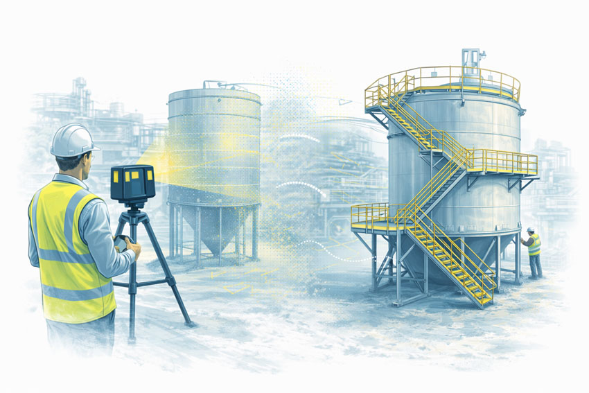
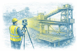
Engineer operating an engineering-grade LiDAR scanner to capture an industrial steel structure for structural drafting and fabrication documentation

Structural Drafting Software โ€” Why Engineering Leadership Matters

Structural drafting underpins how assets are designed, reviewed, fabricated, and built. While there is no shortage of powerful drafting software on the market, successful project outcomes are not defined by software alone โ€” they are defined by engineering judgement applied through the right tools.

At Hamilton By Design, we operate across multiple structural drafting platforms to suit asset risk, fabrication pathways, and project complexity. Below are the five most widely used structural drafting software platforms in industry today โ€” and how they fit into an engineering-led workflow.


AutoCAD โ€” The Industry Baseline for Structural Drafting

AutoCAD remains the most widely accepted platform for 2D structural drafting across Australia.

It is commonly used for:

  • General arrangement drawings
  • Structural sections and details
  • Retrofit and brownfield documentation
  • As-built drawings

AutoCADโ€™s strength lies in its universality and clarity, particularly for issuing IFC documentation. However, on complex or fabrication-heavy projects, AutoCAD alone relies heavily on the experience and discipline of the engineer and drafter producing the drawings.


Revit โ€” Coordinated Structural Documentation in a BIM Environment

Revit enables a model-driven approach to structural drafting, where plans, sections, elevations, and schedules are generated from a single coordinated model.

It is well suited to:

  • Building structures
  • Multidiscipline coordination
  • Projects requiring digital handover or asset information models

While Revit is a powerful coordination tool, its effectiveness depends on engineering control of modelling assumptions, member sizing, and load paths. Without that oversight, models can appear complete while concealing risk.


Engineering-led LiDAR scanning of an industrial steel platform to produce accurate structural drafting data

Tekla Structures โ€” Fabrication-Level Structural Drafting

Tekla Structures is widely recognised as the benchmark platform for steel and concrete detailing.

It is commonly used where:

  • Fabrication accuracy is critical
  • Connection design must be unambiguous
  • CNC data, BOMs, and shop drawings are required

Tekla excels in mining, heavy industry, and complex steel structures where what is modelled is what gets built. Its strength is not simply its software capability, but its ability to enforce constructability and clarity.


Advance Steel โ€” Steel Detailing Within an AutoCAD Environment

Advance Steel extends traditional AutoCAD workflows into 3D steel detailing.

It is often selected where:

  • Fabricators operate primarily in AutoCAD
  • 3D steel modelling is required without a full BIM transition
  • Fabrication drawings and NC data are needed

Advance Steel provides an efficient pathway from drafting to fabrication when applied within an engineering-controlled workflow.


Our clients:


SolidWorks โ€” Structural Drafting for Industrial and Mechanical Assets

SolidWorks is widely used for industrial structures integrated with mechanical equipment.

It is particularly effective for:

  • Platforms, frames, skids, and support structures
  • Conveyors and transfer stations
  • Structures requiring integration with machinery and FEA

For industrial environments, SolidWorks enables structural drafting to be developed in context, reducing interface risk between mechanical and structural elements.


Software Is a Tool โ€” Engineering Is the Outcome

No single software platform is โ€œbestโ€ in all circumstances. Each has strengths depending on:

  • Asset type
  • Fabrication method
  • Risk profile
  • Compliance requirements

The real differentiator is engineering leadership โ€” selecting the right platform, applying the correct standards, and ensuring drawings are fit-for-purpose and fit-for-fabrication.



Hamilton By Design logo displayed on a blue tilted rectangle with a grey gradient background


3D LiDAR scanning and 3D modelling service button โ€” laser scanner capturing a point cloud for engineering and CAD modelling
Mechanical engineering services

Structural Drafting Done Properly

At Hamilton By Design, structural drafting is delivered as part of an engineering-led service, not a drafting-only output. Our work is supported by:

  • Engineering-grade 3D LiDAR scanning
  • Fabrication-ready documentation
  • Australian Standards-aligned detailing
  • Clear accountability from concept through to construction

If your project requires structural drafting that stands up to fabrication, construction, and long-term operation, we can help.


Need Structural Drafting Support?

If youโ€™re planning a new structure, upgrading an existing asset, or preparing fabrication documentation, contact Hamilton By Design to discuss how an engineering-led drafting approach can reduce risk and improve outcomes.


Name
Would you like us to arrange a phone consultation for you?
Address
Finite Element Analysis (FEA) engineering simulation button
Mechanical engineering services

AS ISO 10816 / 20816 โ€“ Mechanical Vibration

AS ISO 10816 & 20816 โ€“ Mechanical Vibration | Hamilton By Design

Mechanical vibration is one of the earliest indicators that rotating equipment is developing a fault. Standards such as AS ISO 10816 and AS ISO 20816 provide a consistent framework for measuring, evaluating, and managing vibration in industrial machinery.

At Hamilton By Design, we help clients apply these standards in a practical, engineering-led way by connecting vibration data with mechanical design, asset condition, and real-world site conditions.


What Are AS ISO 10816 and AS ISO 20816?

The AS ISO 10816 / 20816 standards define:

  • How mechanical vibration should be measured on machines
  • How vibration severity should be evaluated
  • What vibration levels are considered acceptable, marginal, or unacceptable

These standards are commonly applied to motors, pumps, gearboxes, compressors, fans, conveyors, and other rotating equipment where vibration provides an early warning of mechanical or structural issues.


Why Mechanical Vibration Standards Matter

Using vibration data without a recognised standard often leads to inconsistent interpretation and delayed action. Applying AS ISO 10816 / 20816 helps organisations to:

  • Identify mechanical problems early
  • Reduce unplanned downtime and breakdowns
  • Prevent secondary damage to bearings, shafts, and foundations
  • Improve overall equipment reliability
  • Support condition-based and predictive maintenance strategies

When vibration is assessed against an accepted standard, maintenance decisions become clearer and more defensible.


The Common Gap: Vibration Data Without Engineering Context

Many sites collect vibration data but struggle to connect it to:

  • As-installed geometry and alignment
  • Structural stiffness and support conditions
  • Design intent versus site reality
  • Maintenance and modification history

Vibration issues are often symptoms of broader mechanical or structural problems. Without engineering context, vibration data alone can be misleading.

This is where vibration assessment benefits from being connected to engineering-grade site information.

Engineering-Grade 3D LiDAR Scanning
https://www.hamiltonbydesign.com.au/home/engineering-services/engineering-grade-lidar-scanning/


How Hamilton By Design Helps

Hamilton By Design connects vibration standards with practical engineering outcomes through a coordinated service offering.

Engineering-Led Vibration Interpretation

We assess vibration results against AS ISO 10816 / 20816 using engineering judgement rather than relying solely on alarm limits. Machine type, operating duty, and site conditions are all considered.

Understanding the Physical Asset

By linking vibration data with mechanical layouts, drawings, and 3D models, we help identify whether vibration is driven by alignment issues, inadequate stiffness, foundation behaviour, or design constraints.

Mechanical Engineering Services
https://www.hamiltonbydesign.com.au/home/mechanical-engineering-consulting/mechanical-engineering/

SolidWorks & Mechanical CAD Services
https://www.hamiltonbydesign.com.au/home/engineering-services/solidworks/

Analysis Where Required

Where vibration levels indicate potential resonance, flexibility, or dynamic response issues, we support deeper investigation using structural and mechanical analysis tools.

SolidWorks FEA & Simulation
https://www.hamiltonbydesign.com.au/home/engineering-services/solidworks/solidworks-fea-simulation/

FEA Capabilities
https://www.hamiltonbydesign.com.au/home/engineering-services/fea-capabilities/

Clear, Usable Reporting

Our reporting focuses on:

  • What the vibration levels indicate
  • Why the issue matters to the asset
  • What actions are recommended

This ensures vibration results directly support maintenance and engineering decisions.


Where This Approach Adds Value

A connected vibration and engineering approach is particularly valuable in:

  • Mining and mineral processing plants
  • Heavy industrial facilities
  • Energy and utilities infrastructure
  • Brownfield upgrades and asset life-extension projects

Vibration issues are frequently linked to steelwork design, support conditions, or historical modifications that were not fully engineered.

Challenges of Not Consulting AS 3990 โ€“ Mechanical Equipment Steelwork
https://www.hamiltonbydesign.com.au/challenges-of-not-consulting-as-3990-mechanical-equipment-steelwork/

AS 1755 โ€“ Conveyor Safety
https://www.hamiltonbydesign.com.au/as-1755-conveyor-safety/


Summary

AS ISO 10816 and AS ISO 20816 provide the benchmark for assessing mechanical vibration.
Hamilton By Design provides the engineering connection that turns those benchmarks into practical action.

By linking vibration data with 3D scanning, mechanical design, and engineering analysis, vibration assessments become clearer, more accurate, and far more useful across the asset lifecycle.


Hamilton By Design logo displayed on a blue tilted rectangle with a grey gradient background
3D LiDAR scanning and 3D modelling service button โ€” laser scanner capturing a point cloud for engineering and CAD modelling
Mechanical engineering services

Related Engineering Services

3D Laser Scanning & Mechanical Design
https://www.hamiltonbydesign.com.au/3d-laser-scanning-mechanical-design-australia/

Mining Engineering Services
https://www.hamiltonbydesign.com.au/home/engineering-services/mining-engineering-services-australia/

3D LiDAR scanning and 3D modelling service button โ€” laser scanner capturing a point cloud for engineering and CAD modelling
Mechanical engineering services
Finite Element Analysis (FEA) engineering simulation button
Mechanical engineering services

AS 3990 Mechanical Equipment Steelwork | Walkways, Platforms & Conveyor Structures

Engineer using LiDAR scanner to capture as-built tank steelwork, transitioning to compliant AS 3990 walkways and access platforms

AS 3990 โ€“ Mechanical Equipment Steelwork

Walkways, Conveyor Structures, Platforms and Gantries

Mechanical equipment steelwork is everywhere in industrial sites โ€” conveyor structures, access walkways, maintenance platforms, gantries and support frames. Over time, these structures are modified, loaded differently, repaired, and upgraded. Thatโ€™s where AS 3990 โ€“ Mechanical equipment โ€“ Steelwork becomes critical: it provides a framework for designing and verifying steelwork that supports mechanical equipment and associated access systems.

At Hamilton By Design, we help asset owners and project teams reduce risk by converting real as-built steelwork into engineering-grade digital models that can be checked, upgraded, and documented with confidence.


3D LiDAR scanning of industrial tank steelwork showing as-built condition and engineered walkways and stairs designed to AS 3990

When AS 3990 Steelwork Becomes a Problem in the Real World

Steelwork rarely fails because it was โ€œobviously wrongโ€ on day one. The most common issues develop gradually due to changes in loading, upgrades, corrosion, or incomplete documentation.

Common triggers we see on site

  • New conveyor drives, chutes, skirts, guards, or pull-wire systems added after commissioning
  • Extra services added: cable trays, hose reels, water lines, pipework, and supports
  • Walkway changes for access, maintenance, or guarding upgrades
  • Localised damage from impact, vibration, or operational fatigue
  • Corrosion or section loss in wash-down areas, coastal environments, or chemical exposure zones
  • Legacy steelwork with missing drawings or unknown load assumptions

If you canโ€™t prove what exists (accurately), it becomes difficult to prove compliance, fitness-for-purpose, or due diligence.


Key Engineering Risks with Walkways, Platforms, Gantries and Conveyor Structures

1) Design intent vs as-built reality

Many sites have steelwork that differs from drawings due to shutdown modifications or brownfield constraints. Small deviations in member size, connection detailing, or geometry can materially change structural performance.

2) Loads have changed โ€” but the steelwork didnโ€™t

A โ€œsimpleโ€ modification can add significant load: added services, heavier equipment, changed maintenance practices, or multiple personnel working in the same bay. These changes can push members or connections beyond the original assumptions.

3) Conveyor vibration and dynamic effects

Conveyor structures experience cyclic loading, start/stop effects, and vibration. Even if the structure looks acceptable, fatigue and resonance can become a long-term reliability problem โ€” particularly around drive stations, transfer points, and cantilevered platforms.

4) Connection adequacy often governs

Field-welded brackets, modified gussets, bolt slip, corroded fasteners, and non-standard connection geometry can become the weak link. Connection performance is frequently the true limiting factor in older or heavily modified steelwork.

5) Access and safety interfaces

Walkways and platforms often sit at the intersection of multiple requirements: safe access geometry, handrails, toe-boards, gates, and guarding. If access steelwork was modified without a proper verification step, the risk becomes both structural and safety-related.


What โ€œVerificationโ€ Looks Like in Practice

AS 3990 steelwork compliance is not just a box-tick. In a practical project environment, it means you can answer:

  • What steelwork exists right now (as-built)?
  • What loads and operational conditions apply today (not ten years ago)?
  • Are members and connections adequate under realistic scenarios?
  • What upgrades are required, and can they be fabricated to fit first time?
  • Can the asset owner document compliance and risk controls for governance?

Hamilton By Design supports this process by bringing LiDAR scanning + mechanical engineering + fabrication-ready outputs together under one roof.


How Hamilton By Design Helps (Our Typical Deliverables)

1) Engineering-grade 3D LiDAR scanning of steelwork

We capture accurate geometry of:

  • Walkways and access platforms
  • Conveyor stringers, trestles, and transfer towers
  • Gantries, monorails, and maintenance frames
  • Supports, bracing, ladders, stairs, and access interfaces

Related service:
3D Laser Scanning: https://www.hamiltonbydesign.com.au/3d-laser-scanning/

2) As-built CAD model for verification and design

We convert the scan into usable engineering outputs such as:

  • As-built 3D CAD models
  • Key dimensions, levels, and clearances
  • Interference checking and fit-up planning
  • Fabrication-ready drawings for retrofit steelwork

3) Engineering checks and upgrade design

Where required, we support structural verification and upgrade design using engineering workflows suited to brownfield assets.

Related capability:
SolidWorks FEA / simulation workflows: https://www.hamiltonbydesign.com.au/home/solidworks/solidworks-fea-simulation/


Where This Matters Most (Typical Applications)

  • Conveyor upgrades and transfer station modifications
  • Walkway widening, new stair access, and maintenance platform additions
  • Guarding upgrades, pull-wire additions, and access compliance programs
  • Corrosion repairs and local strengthening
  • Brownfield plant modifications with limited shutdown time
  • Audit readiness and engineering documentation clean-up

If youโ€™re working around conveyors, you may also find this relevant:
AS 1755 Conveyor Safety: https://www.hamiltonbydesign.com.au/as-1755-conveyor-safety/

And for safety leadership context:
Machine guarding lessons: https://www.hamiltonbydesign.com.au/machine-guarding-in-australia-a-decade-of-lessons-for-leaders-asset-owners-and-engineers/


Standards and Compliance Context (How AS 3990 Fits In)

AS 3990 typically sits alongside a broader compliance context depending on the asset and scope. In many industrial environments, it may interact with standards and guidance such as:

  • AS 1657 (fixed platforms, walkways, stairways and ladders)
  • AS 4100 (steel structures)
  • AS/NZS 1170 (structural actions / loading)
  • AS 1755 (conveyor safety and associated interfaces)

For official sources and governance context:

(Note: Always confirm the current revision and applicability of standards for your site, scope, and jurisdiction.)


Why Digital As-Built Matters for AS 3990 Steelwork

A verified as-built model reduces:

  • Upgrade risk and fabrication rework
  • Shutdown time lost to unexpected clashes
  • Safety risks from undocumented modifications
  • Compliance gaps during audits and governance reviews

It also supports โ€œfit-first-timeโ€ fabrication because designers, engineers, and fabricators are working from the same geometry โ€” not assumptions.


Talk to an Engineer About Your AS 3990 Steelwork

If youโ€™re planning an upgrade, responding to an audit, or unsure whether existing walkways, platforms, gantries or conveyor structures still meet their intended duty, we can help you quickly establish a reliable baseline.

Start with scanning, modelling, and engineering verification โ€” and build from facts.

Related service pages to explore:

Hamilton By Design logo displayed on a blue tilted rectangle with a grey gradient background
3D LiDAR scanning and 3D modelling service button โ€” laser scanner capturing a point cloud for engineering and CAD modelling
Mechanical engineering services

Our clients:

Name
Would you like us to arrange a phone consultation for you?
Address
https://youtu.be/jOGYoLL1Vro?si=vPkEAPQiFzB9fd6-

Mechanical Engineering | Structural Engineering


Detailing Transfer Stations in the Age of Digital Engineering

Transfer stations and chutes sit at the intersection of bulk materials handling, structural engineering, and fabrication practicality. While the fundamentals of good detailing have not changed, the way engineers now capture, coordinate, and validate these details has evolved significantly over the past decade.

This article revisits the principles of transfer station detailing and places them in a modern digital-engineering context, where accurate site data, constructability, and lifecycle performance are critical.


Engineering illustration of a transfer chute showing a LiDAR point cloud overlay aligned with the same chute geometry for as-built verification.
3D LiDAR scanning and 3D modelling service button โ€” laser scanner capturing a point cloud for engineering and CAD modelling
Mechanical engineering services

Why Transfer Station Detailing Still Matters

Poorly detailed transfer stations remain one of the most common sources of:

  • Material spillage and dust generation
  • Accelerated liner and structure wear
  • Unplanned downtime and maintenance escalation
  • Safety risks to operators and maintainers

In many cases, the root cause is not the concept design, but inadequate detailing and incomplete understanding of site geometry.

Even well-intended designs can fail if:

  • Existing structures are misrepresented
  • Conveyor interfaces are assumed rather than measured
  • Fabrication tolerances are not realistically achievable on site

The Shift from Assumed Geometry to Measured Reality

Historically, detailing relied heavily on:

  • Legacy drawings
  • Manual tape measurements
  • Partial site surveys
  • โ€œBest guessโ€ alignment assumptions

Today, engineering-grade reality capture has fundamentally changed what is possible.

Using 3D laser scanning (LiDAR), engineers can now work from:

  • Millimetre-accurate point clouds
  • Verified conveyor centre lines
  • True chute-to-structure interfaces
  • Real as-installed conditions rather than design intent

This shift dramatically reduces site rework and fabrication clashes.

This approach is central to how Hamilton By Design supports bulk materials handling upgrades across mining, ports, and heavy industry.


Detailing Considerations That Still Get Missed

Even with modern tools, certain detailing fundamentals remain critical.

1. Interface Accuracy

Transfer stations often interface with:

  • Existing conveyors
  • Walkways and access platforms
  • Structural steelwork installed decades earlier

Without accurate as-built data, small errors compound quickly. Laser scanning eliminates this uncertainty.

Related reading:
https://www.hamiltonbydesign.com.au/3d-laser-scanning-engineering/


2. Wear Liner Integration

Good detailing must account for:

  • Liner thickness variation
  • Fixing access and replacement paths
  • Load paths through liners into structure

Digitally modelling liners within the chute geometry allows engineers to validate:

  • Clearances
  • Installation sequence
  • Maintenance access before steel is cut

3. Fabrication Reality

A detail that looks acceptable in 2D can become problematic when fabricated.

Modern workflows now link:

  • 3D scanning
  • Solid modelling
  • Fabrication drawings
  • Digital QA checks

This reduces site modifications and ensures components fit first time.

Example of fabrication-ready workflows:
https://www.hamiltonbydesign.com.au/mechanical-engineering-design-services/


Transfer Stations as Systems, Not Isolated Chutes

A key lesson reinforced over time is that transfer stations must be treated as systems, not standalone components.

Good detailing considers:

  • Upstream and downstream belt tracking
  • Material trajectory consistency
  • Structural vibration and dynamic loading
  • Maintenance access under real operating conditions

Digital engineering allows these interactions to be reviewed early, reducing operational risk.


The Role of Engineering-Led Scanning

Not all scans are equal.

For engineering applications, scanning must be:

  • Performed with known accuracy
  • Registered and verified correctly
  • Interpreted by engineers, not just technicians

This distinction matters when designs are used for fabrication and compliance.

Hamilton By Designโ€™s approach combines engineering-led LiDAR scanning with mechanical design, ensuring the data collected is suitable for real engineering decisions.

Learn more:
https://www.hamiltonbydesign.com.au/engineering-led-3d-lidar-scanning/


Closing Thoughts

While detailing principles for transfer stations have stood the test of time, the tools and expectations have changed.

Modern projects demand:

  • Verified geometry
  • Fabrication-ready models
  • Reduced site risk
  • Higher confidence before steel is ordered

By integrating reality capture, detailed modelling, and constructability thinking, transfer station detailing can move from a risk point to a performance advantage.


Hamilton By Design logo displayed on a blue tilted rectangle with a grey gradient background

Our clients:


Name
Would you like us to arrange a phone consultation for you?
Address

Further Reading

3D LiDAR scanning and 3D modelling service button โ€” laser scanner capturing a point cloud for engineering and CAD modelling
Mechanical engineering services
Finite Element Analysis (FEA) engineering simulation button
Mechanical engineering services

AS 1755 Conveyor Safety

Engineer reviewing a guarded conveyor system with fixed side and nip-point guards designed to prevent access to moving parts.

Designing Conveyor Guarding for Compliance, Safety, and Practical Operation

Conveyors are widely used across processing, manufacturing, and materials-handling environments, but they also present some of the most persistent safety risks in industrial operations. Entrapment, nip points, rotating components, and maintenance access are all recognised hazards that must be managed through proper design and guarding.

In Australia, these risks are addressed through AS 1755 โ€“ Conveyors โ€“ Safety Requirements, which establishes the minimum safety expectations for conveyor systems across their full lifecycle, from design and installation through to operation and maintenance.

This article outlines what AS 1755 requires, why compliant conveyor guarding is critical, and how engineering-led design plays a key role in achieving practical safety outcomes.


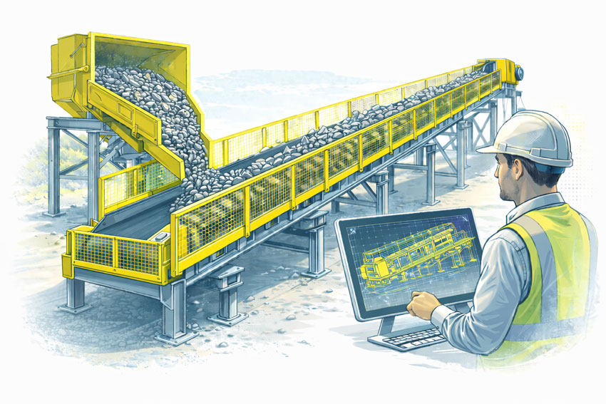
Bulk materials conveyor with compliant safety guarding at the hopper, tail end, and along the conveyor, shown with an engineer reviewing guarding design drawings.
3D LiDAR scanning and 3D modelling service button โ€” laser scanner capturing a point cloud for engineering and CAD modelling
Mechanical engineering services

What Is AS 1755?

AS 1755 is the Australian Standard that defines safety requirements for belt conveyors and other conveyor systems. It addresses both new and existing installations and applies to conveyors used in industrial, commercial, and processing environments.

Rather than focusing on individual guarding components in isolation, AS 1755 considers the conveyor system as a whole, including how people interact with it during normal operation, inspection, cleaning, and maintenance.

The standard is referenced by regulators, safety professionals, and engineers as the primary benchmark for conveyor safety in Australia.


Key Safety Principles in AS 1755

AS 1755 is built around a number of core safety principles that influence how conveyor guarding should be designed.

These include eliminating hazards where possible, controlling remaining risks through engineering solutions, and ensuring that guarding does not introduce new risks by restricting access or encouraging unsafe behaviour.

In practice, this means that compliant guarding must be effective, durable, and suitable for the operating environment, while still allowing conveyors to be inspected, cleaned, and maintained safely.


Conveyor Guarding Requirements

A major focus of AS 1755 is the control of access to hazardous areas. This includes guarding of:

  • Drive pulleys and tail pulleys
  • Return rollers and idlers
  • Nip points and shear points
  • Rotating shafts and couplings
  • Chain drives, belt drives, and gearboxes

Guarding must be designed so that body parts cannot access hazardous zones, taking into account reach distances, openings, and the position of the conveyor relative to walkways or platforms.

Importantly, AS 1755 recognises that guarding must be fit for purpose. Poorly designed guards that are difficult to remove, inspect, or maintain are often bypassed or removed altogether, creating new safety risks.


Fixed Guards vs Interlocked Guards

AS 1755 allows for different types of guarding depending on the application and risk profile.

Fixed guards are commonly used where access is not required during normal operation. These guards must be securely fixed and require tools for removal.

Interlocked guards may be required where regular access is necessary. These systems ensure that the conveyor cannot operate while the guard is open or removed, reducing the risk of exposure to moving parts.

Selecting the appropriate guarding strategy requires an understanding of how the conveyor is used in practice, not just how it appears on drawings.


Existing Conveyors and Retrofit Challenges

Many conveyors currently in service were installed before the latest versions of AS 1755 were adopted. In these cases, compliance is often achieved through retrofit guarding rather than full replacement.

Retrofitting guarding to existing conveyors introduces additional challenges, including:

  • Limited space around existing equipment
  • Incomplete or outdated drawings
  • Structural constraints
  • Ongoing operation during upgrades

Engineering-led assessment and accurate documentation of existing conditions are critical when designing retrofit guarding solutions that comply with AS 1755 without disrupting operations.


The Role of Engineering in Conveyor Guarding Design

AS 1755 does not provide prescriptive โ€œone-size-fits-allโ€ guard designs. Instead, it sets performance requirements that must be interpreted and applied by competent professionals.

Engineering input is essential to ensure that conveyor guarding:

  • Addresses all relevant hazards
  • Integrates with existing mechanical and structural systems
  • Can be fabricated and installed accurately
  • Supports safe maintenance and inspection activities

Poorly engineered guarding may appear compliant on paper but fail in real-world use.


Documentation, Verification, and Ongoing Safety

Compliance with AS 1755 is not a one-time activity. Conveyor systems evolve over time as layouts change, equipment is upgraded, and operating practices shift.

Clear documentation of guarding design, installation, and assumptions provides a baseline for future modifications and safety reviews. This documentation is also critical when demonstrating due diligence to regulators or during incident investigations.


Why AS 1755 Matters

AS 1755 exists to prevent serious injuries and fatalities associated with conveyor systems. When applied correctly, it provides a structured framework for identifying hazards, implementing effective controls, and maintaining safe operation over the life of the equipment.

Achieving compliance requires more than installing mesh around moving parts. It requires understanding how people interact with conveyors and designing guarding that supports safe behaviour rather than working against it.


Hamilton By Design logo displayed on a blue tilted rectangle with a grey gradient background

Conveyor guarding designed in accordance with AS 1755 is a critical component of safe industrial operations. Engineering-led design, accurate documentation, and practical consideration of maintenance and operation are essential to achieving compliance that works in practice.

When conveyor safety is treated as an engineering problem rather than a checkbox exercise, the result is safer equipment, fewer incidents, and more reliable operations.

Manufacturing and production services button

Our clients


Name
Would you like us to arrange a phone consultation for you?
Address

3D CAD Modelling Australia service banner for Hamilton By Design


CHPP Engineering title graphic featuring bold white text reading "CHPP Engineering" centred on a blue rounded rectangle background.
Pipework Drafting title graphic featuring bold white text reading "Pipework Drafting" centred on a blue rounded rectangle background.
3D LiDAR Scanning for Engineering Projects title graphic featuring bold white text on a blue rounded rectangle background.


Finite Element Analysis (FEA) engineering simulation button
Structural drafting services button
Mechanical drafting services button


Australian Drafting logo featuring bold white text reading "Australian Drafting" centred on a blue rounded rectangle background.
Engineering Governance title graphic featuring bold white text reading "Engineering Governance" centred on a blue rounded rectangle background.
Engineering-Grade LiDAR Scanning title graphic featuring bold white text on a blue rounded rectangle background.


Mechanical drafting services button
Structural drafting services button


Fabrication and product design services
3D CAD Modelling Australia service banner for Hamilton By Design
Mechanical, Structural & Pipework Drafting service banner by Hamilton By Design featuring white text on a blue background.


3D LiDAR scanning and 3D modelling service button โ€” laser scanner capturing a point cloud for engineering and CAD modelling
Mechanical engineering services

Mechanical Engineering | Structural Engineering


Machine Guarding in Australia: A Decade of Lessons for Leaders, Asset Owners, and Engineers

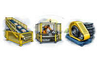
ndustrial machine guarding solutions showing a conveyor system, a robotic cell, and a belt drive with fixed guards designed to prevent access to hazardous moving parts.

Machine guarding examples showing a guarded conveyor, enclosed robotic cell, and belt drive with safety covers

3D LiDAR scanning and 3D modelling service button โ€” laser scanner capturing a point cloud for engineering and CAD modelling
Mechanical engineering services

Machine guarding remains one of the most persistent and preventable safety risks across Australian industry.
Despite improvements in automation, safety culture, and regulatory oversight, serious injuries and fatalities involving machinery continue to occur every year, particularly in manufacturing, mining, food processing, and materials handling.

Over the past decade, regulators, courts, and insurers have consistently reinforced one message:
machine guarding is not optional, not administrative, and not a โ€œfit-laterโ€ activity โ€” it is a core engineering and governance responsibility.

This article examines:

  • The international and Australian standards framework for machine guarding
  • Accident and injury trends over the past ten years
  • Legal and enforcement signals emerging from prosecutions
  • Why machine guarding must be treated as a strategic asset-risk issue, not just a safety task

The Global Framework: International Standards for Machine Guarding

Machine guarding is governed globally through standards developed by the International Organization for Standardization (ISO).


ISO standards portal
Core International Standards

ISO 12100 Risk assessment

ISO 14120 Guard design

ISO 13857 Safety distances

ISO 13849-1 Interlocks & control systems

These standards establish a risk-based engineering approach, requiring hazards to be:

  1. Identified
  2. Eliminated where possible
  3. Engineered out through guards and control systems
  4. Verified through geometry, distances, and fail-safe logic

This methodology underpins CE marking, global OEM compliance, and multinational EPC project delivery.


The Australian Context: AS 4024 and WHS Expectations

Australia adopts and localises ISO principles through AS 4024 โ€“ Safety of Machinery, referenced extensively by regulators under Work Health and Safety (WHS) legislation.

Standards Australia โ€“ AS 4024 Series
Key Australian Standards

AS 4024.1201 Risk assessment

AS 4024.1601 Guards

AS 4024.1602 Interlocks

AS 4024.1801 Safety distances

AS 4024.1501 Safety control systems

While standards themselves are not legislation, courts and regulators consistently use AS 4024 as the benchmark for determining whether risks have been managed so far as is reasonably practicable.


Australia does not publish a dedicated โ€œmachine guarding accidentโ€ metric. However, national data from Safe Work Australia clearly shows machinery remains a leading cause of serious harm.

Safe Work Australia โ€“ Key WHS statistics:
National Trends (Approximate โ€“ Last 10 Years)

MetricEvidence Source
~1,850+ traumatic work fatalitiesSafework Australia
~180โ€“200 fatalities per yearSafework Australia
Highest fatality rateMachinery operators & drivers
~130,000โ€“140,000 serious injury claims annuallyAustralian Institute of health and welfare
Common mechanismsTrapped by machinery, struck by moving objects

Machinery operators consistently record:

  • The highest fatality rates of all occupation groups
  • Disproportionate representation in serious injury claims
  • Higher exposure to entanglement, crush, shear, and impact hazards

These mechanisms are directly linked to guarding effectiveness, not worker behaviour alone.


What Hasnโ€™t Changed โ€” and Why It Matters

1. Legacy Plant Remains a Key Risk

Many incidents involve:

  • Older machinery
  • Brownfield modifications
  • Equipment altered without re-engineering guarding

Australian WHS law does not grandfather unsafe plant.


2. Guarding Is Still Added Too Late

Common failures include:

  • Guards designed post-fabrication
  • Inadequate reach distances
  • Interlocks added without validated performance levels

This often leads to bypassing, removal, or unsafe maintenance practices.


3. Lack of Engineering Documentation

Post-incident investigations frequently identify:

  • No formal risk assessment
  • No justification against AS 4024 or ISO standards
  • No evidence that guarding was engineered, tested, or validated

In legal proceedings, absence of documentation is treated as absence of control.


Australian regulators (WorkSafe NSW, WorkSafe VIC, SafeWork QLD, SafeWork SA) have consistently prosecuted machine-guarding failures, particularly where:

  • Hazards were known
  • Improvement notices were ignored
  • Guards were removed or ineffective

Regulator portals:

Courts have reinforced that:

  • Training does not replace guarding
  • PPE does not replace guarding
  • Signage does not replace guarding

Guarding as a Governance Issue

For executives and boards, machine guarding intersects with:

  • Officer due diligence obligations
  • Asset lifecycle risk
  • Insurance and liability exposure
  • Business continuity and ESG performance

Well-designed guarding:

  • Reduces downtime
  • Enables safer automation
  • Improves workforce confidence
  • Creates defensible compliance positions

The Engineering Reality: Geometry Drives Compliance

Modern compliance relies on:

  • Verified reach distances
  • Measured openings and clearances
  • Validated interlock logic

This is why accurate:

  • As-built capture
  • 3D modelling
  • Engineering-grade spatial data

are increasingly essential for brownfield and high-risk plant.


Looking Ahead: The Next Decade

Trends indicate:

  • Greater scrutiny of legacy machinery
  • Stronger linkage between standards and prosecutions
  • Higher expectations for engineering evidence
  • Increased use of digital engineering to prove compliance

Organisations that integrate guarding early into engineering workflows will be better protected legally, operationally, and reputationally.


Hamilton By Design logo displayed on a blue tilted rectangle with a grey gradient background

Final Thought

Machine guarding is not about mesh and fences.
It is about engineering intent, risk ownership, and accountability.

The last decade of Australian data, prosecutions, and standards alignment is clear:
when guarding fails, the outcomes are predictable โ€” and preventable.

Structural drafting services button
3D LiDAR scanning and 3D modelling services button
Mechanical drafting services button

Our clients:

Name
Would you like us to arrange a phone consultation for you?
Address

#Machine guarding standards Australia #Machinery safety best practices #AS/NZS 4024 machine guarding #Workplace safety machinery #Industrial safety compliance #Machine guarding lessons for engineers

Finite Element Analysis (FEA) engineering simulation button
Mechanical engineering services