Toowoombaโ€™s Engineering Future

Toowoombaโ€™s Engineering Future: How 3D LiDAR Scanning & Digital Modelling Are Transforming Projects Across the Darling Downs


Toowoomba is quickly becoming one of Australiaโ€™s most important regional powerhouses โ€” a city where agriculture, logistics, mining, construction and manufacturing intersect at a scale rarely seen outside capital cities. With major infrastructure investments, the growth of the Toowoomba Wellcamp Airport, and its position as a gateway to the Surat Basin and the Darling Downs, the region is undergoing a steady shift toward digitally enabled engineering and smarter project delivery.

At Hamilton By Design, weโ€™re incredibly proud to support this growth by providing 3D LiDAR laser scanning, mechanical engineering consulting, 3D modelling and drafting, and digital quality assurance tailored specifically for the demands of Toowoombaโ€™s industrial, commercial and rural sectors.

In this article, we explore why Toowoomba is so unique, the role of modern engineering technology in the region, and how accurate site data and digital models are helping local businesses reduce rework, improve safety and deliver better project outcomes.


Why Toowoomba Is the Perfect Fit for Modern Digital Engineering

Toowoomba is Australiaโ€™s largest inland city outside Canberra, with more than 180,000 people and an economy driven by a mix of agriculture, logistics, manufacturing, construction and energy projects. Its elevated position on the Great Dividing Range, combined with its access to the Surat Basin and major rural supply chains, makes it a critical service hub for heavy industry and regional infrastructure.

But what really sets Toowoomba apart is its transformation into a logistics and engineering centre. With Inland Rail connections, Wellcamp Airportโ€™s freight terminal and constant agricultural expansion, the demand for precise, reliable engineering data has grown rapidly.

This is where 3D LiDAR scanning and digital engineering provide enormous value.


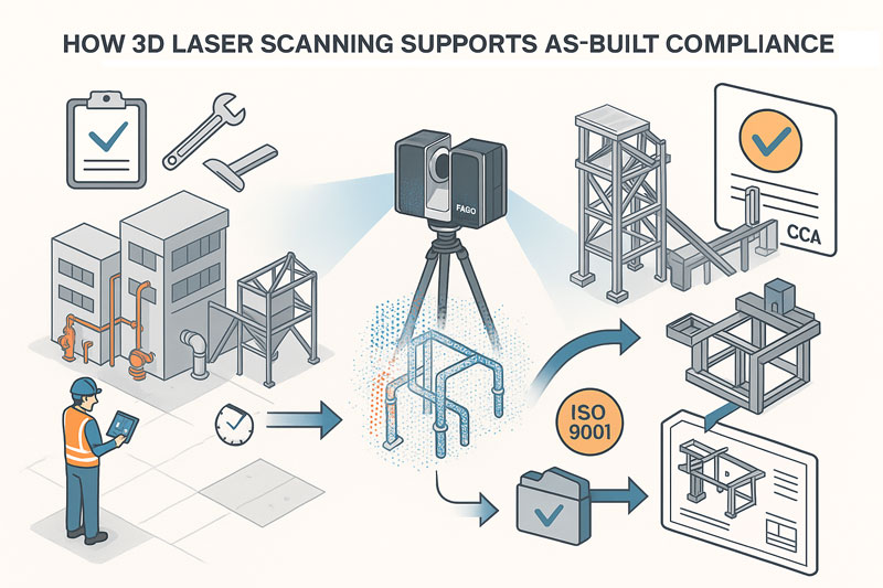
3D LiDAR Laser Scanning: Bringing Millimetre-Level Accuracy to Local Projects

Whether youโ€™re working on a feed mill upgrade, a manufacturing facility expansion, a rural processing plant, a logistics warehouse fit-out or a mining-related modification, accurate site measurements are essential. Traditional surveys struggle to capture the complex geometry, alignment issues or hidden interferences common in brownfield environments.

Engineering-grade 3D LiDAR scanning solves this problem instantly.

Hamilton By Design uses high-accuracy terrestrial laser scanners capable of capturing:

  • complex plant layouts
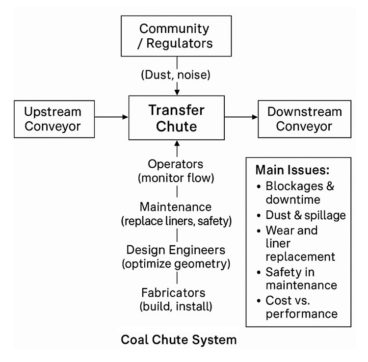
  • conveyors, chutes, structural frames
  • pipework routing and clashes
  • equipment misalignment
  • deflections, corrosion and wear
  • existing foundations and tie-in points
  • site terrain and building envelopes

All delivered with millimetre-level accuracy.

For Toowoomba businesses, this means:

  • reduced rework
  • faster fabrication
  • fewer shutdown overruns
  • safer installations
  • accurate as-built documentation

In a region where travel, mobilisation and shutdown timing matter, these improvements translate directly into cost savings and smoother project execution.


3D Modelling & Drafting for Toowoomba Industry

After scanning, the next step is turning point-cloud data into intelligent 3D models and fabrication-ready drawings.

Hamilton By Design specialises in:

  • SolidWorks mechanical modelling
  • structural modelling for plant systems
  • equipment layouts and upgrade designs
  • skid-based systems
  • brownfield modification design
  • drawing packages (GA, detail, isometric, BOMs)

For Toowoomba industries โ€” especially manufacturing workshops, agri-processing facilities, grain-handling plants, transport depots and rural engineering contractors โ€” accurate 3D models significantly improve design coordination.

We often hear clients say:

โ€œWe used to rely on tape measures and photos. Now we can see the entire plant from our office.โ€

That is exactly the transformation 3D modelling provides.


Mechanical Engineering for Brownfield Upgrades Across the Darling Downs

The Toowoomba region is rich in brownfield mechanical assets:
farm infrastructure, conveyor systems, grain silos, batching plants, food-processing lines, workshops, energy facilities and quarry machinery.

Hamilton By Design provides engineering support such as:

  • mechanical design for upgrades
  • structural integrity assessments
  • vibration, alignment and deflection reviews
  • buckling, fatigue and stress analysis (FEA)
  • chute, pipework and mechanical flow improvements
  • equipment mounting, lifting and access design

Our combination of engineer-led scanning + mechanical design ensures that every upgrade fits the first time and is supported by real data.


Why 3D Laser Scanning Is a Game-Changer for Toowoomba

Hereโ€™s where Toowoomba really benefits compared to many inland cities:

1. Large Agricultural Facilities Need Accurate Layouts

Feedlots, grain silos, packing sheds, processing plants and cold-storage facilities often evolve over many years. Scanning helps document these environments for compliance, redesign and expansion.

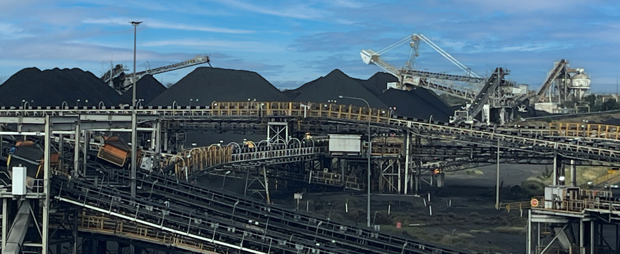
2. The Region Supports Mining & Energy Projects

Toowoomba acts as a service centre for the Surat Basin โ€” Dalby, Chinchilla, Miles, Roma.
LiDAR enables accurate tie-in points, pipe upgrades and shutdown planning.

3. Manufacturing & Fabrication Are Growing

Local workshops need precise data to avoid rework. Models based on point clouds give fabricators total confidence before cutting steel.

4. Logistics Infrastructure Continues Expanding

Wellcamp Airport, industrial estates and new warehousing projects benefit from accurate as-built documentation to speed up development approvals and construction decisions.

5. Reducing Travel Costs Is Critical for Regional Projects

A single scan eliminates multiple site trips โ€” crucial for Toowoombaโ€™s broad geographic service area.


Types of Toowoomba Projects Hamilton By Design Supports

Here are some of the local project types where our team adds immediate value:

  • grain-handling plant upgrades
  • feed mill expansions
  • water treatment & pumping stations
  • abattoir & food facility engineering
  • conveyor & materials-handling systems
  • batching plant upgrades
  • workshop fit-outs and machinery layouts
  • logistics warehouse redesigns
  • rural industrial buildings
  • mechanical equipment retrofits
  • energy & utility infrastructure

Whether itโ€™s a small workshop or a multi-hectare industrial site, LiDAR scanning gives project teams a crystal-clear digital representation of the site.


Single-Source Accountability:

Scanning โ†’ Modelling โ†’ Engineering โ†’ Drawings

One of the biggest frustrations in regional engineering is fragmented contractors โ€” one team scans, another models, another designs, and nobody takes responsibility when things donโ€™t align.

Hamilton By Design solves this with an integrated workflow:

  1. 3D LiDAR scan of the site
  2. Registration and accuracy validation
  3. 3D CAD modelling (SolidWorks)
  4. Mechanical & structural engineering
  5. Fabrication-ready drawings
  6. Digital QA and installation support

Everything is handled by a single engineering-led team.


Toowoombaโ€™s Future Needs Digital Engineering โ€” And Weโ€™re Here to Support It

Toowoomba is entering a decade of growth โ€” new industrial estates, expansions in agri-processing, energy transformation, airport-driven logistics and inland infrastructure.
Digital engineering will be a major part of how these projects are delivered efficiently and safely.

Hamilton By Design logo displayed on a blue tilted rectangle with a grey gradient background

Hamilton By Design is excited to provide Toowoomba businesses with:

  • precise 3D LiDAR scanning
  • mechanical engineering and assessment
  • professional 3D modelling and drafting
  • fabrication-ready design
  • digital documentation and QA

Whether youโ€™re planning a small plant improvement or a major regional upgrade, our data-driven approach helps you design with confidence.

How 3D Laser Scanning Supports As-Built Documentation Under Australian Building Codes & Legal Requirements

illustration of 3d scanning and building code of australia

1. What the Building Code of Australia (BCA) and Australian Standards Require

While the BCA (part of the National Construction Code โ€“ NCC) does not mandate 3D laser scanning, it does mandate that:

You must provide accurate, verifiable as-built documentation, including:

  • As-built drawings reflecting what was actually constructed
  • Evidence that construction aligns with design intent and approvals
  • Documentation for certification, compliance, commissioning and future maintenance

These requirements flow through:

  • NCC Volume 1 โ€“ Construction documentation, fire systems, mechanical services
  • AS 1100 โ€“ Technical drawing standards
  • AS 5488 โ€“ Subsurface utility information
  • AS 9001/ISO 9001 โ€“ Quality management documentation
  • State-based WHS / Plant Safety legislation
  • Engineering registration Acts (NSW, QLD, VIC)
  • Client-specific QA frameworks (e.g., TfNSW Digital Engineering, mining compliance standards, government project handover requirements)

These frameworks all emphasise accuracy, traceability, verification and record-keeping.


2. Common Problems with Traditional As-Built Documentation

Most non-compliance issues in handover packages arise because traditional methods rely on:

  • Manual tape measurements
  • Incomplete mark-ups on outdated drawings
  • Limited site access
  • Errors stacking up across multiple trades
  • No accurate record of clashes and deviations
  • No evidence trail for certifiers

This often results in:

  • Disputes between builders, certifiers and subcontractors
  • Rework costs during commissioning
  • Safety risks due to undocumented services or variations
  • Delays in obtaining Occupation Certificates (OC)

3. How 3D Laser Scanning Directly Supports Legal & BCA/NCC Compliance

โœ” 3D Scanning Provides โ€œVerified As-Constructed Evidenceโ€

Point clouds record geometry with millimetreโ€“level accuracy, giving:

  • Audit-proof evidence of what exists
  • Time-stamped scanning sessions
  • A defensible digital record for certifiers, engineers and auditors

This is extremely helpful for:

  • Compliance sign-off
  • Dispute resolution
  • Safety compliance
  • Future upgrades or modifications

โœ” Produces Accurate As-Built Drawings That Meet AS 1100 Requirements

Laser scanning allows you to generate:

  • Certified 2D as-built drawings
  • 3D models
  • Fabrication-ready details
  • Clash-free spatial coordination drawings

This ensures:

  • Dimensions are correct
  • Penetrations, fall directions, service locations and structural offsets are true to field conditions
  • All documentation aligns with NCC-required accuracy

โœ” Eliminates Measurement Errors That Could Breach Compliance

Regulators and certifiers need as-built documents to match constructed work.

Laser scanning:

  • Removes subjective tape measurements
  • Captures difficult/unsafe areas safely
  • Ensures penetrations, ductwork, pipe routes and tolerances match required clearances
  • Supports inspections under NCC (fire, structural, mechanical, accessibility, plant rooms, etc.)

โœ” Simplifies BCA Documentation for Fire, Mechanical & Structural Systems

Scanning assists with validating:

Fire Safety Systems

  • Hydrants, hose reels, fire pump rooms
  • Fire damper locations
  • Egress paths and spatial compliance
  • Service penetrations

Mechanical Systems

  • Duct routes
  • Plant room layouts
  • Fan coil units / AHU placement
  • Shaft centre-lines
  • Compliant access paths

Structural Elements

  • Columns
  • Beams
  • Brackets
  • Plant mounts
  • Retrofitted steelwork
  • Tolerance checks

The point cloud provides certifiers with confidence that what was installed does not deviate from approved plans beyond allowable tolerances.


โœ” Strengthens ISO 9001 & Government QA Requirements

Most government tenders (TfNSW, Defence, Health Infrastructure, QBuild, etc.) require:

  • Traceable QA
  • As-constructed verification
  • Digital documentation

A 3D scan becomes proof of measurement, improving your QA process by providing:

  • Verifiable dimensional control
  • Pre-fabrication QA
  • Handover packages that exceed minimum compliance

4. How Hamilton By Design Can Position This Service

3D Laser Scanning Enables:

  • NCC-compliant as-built documentation
  • Faster certifier approval
  • Fewer construction disputes
  • Reduced rework during commissioning
  • Better safety compliance
  • Accurate digital twins for maintenance and lifecycle management

You can state (truthfully):

โ€œOur 3D scans provide defensible, audit-ready as-built records that satisfy NCC, engineering, and certification requirements. Certifiers appreciate the precision because it removes ambiguity and reduces approval delays.โ€


Hamilton By Design logo displayed on a blue tilted rectangle with a grey gradient background

Why Shutdown Parts Donโ€™t Fit

Accuracy of 3D LiDAR Scanning With FARO

Mechanical Engineering | Structural Engineering

Mechanical Drafting | Structural Drafting

3D CAD Modelling | 3D Scanning

Chute Design

Bridging Reality and Design: How 3D Scanning + 3D Modelling Supercharge Mining Process Plants

In mining and mineral processing environments, small mis-fits, outdated drawings, or inaccurate assumptions can translate into shutdowns, costly rework, or worse, safety incidents. For PMs, superintendents, engineering managers and plants operating under heavy uptime and safety constraints, combining 3D scanning and 3D modelling isnโ€™t just โ€œnice to haveโ€ โ€” itโ€™s becoming essential. At Hamilton By Design, weโ€™ve leveraged this combination to deliver greater predictability, lower cost, and improved safety across multiple projects.


What are 3D Scanning and 3D Modelling?

  • 3D Scanning (via LiDAR, laser, terrestrial/mobile scanners): captures the existing geometry of structures, equipment, piping, chutes, supports, tanks, etc., as a dense point cloud. Creates a digital โ€œreality captureโ€ of the plant in its current (often messy) state.
  • 3D Modelling: turning that data (point clouds, mesh) into clean, usable engineering-geometry โ€” CAD models, as-built / retrofit layouts, clash-detection, wear mapping, digital twins, etc.

The power comes when you integrate the two โ€” when the reality captured in scan form feeds directly into your modelling/design workflows rather than being a separate survey activity thatโ€™s then โ€œinterpretedโ€ or โ€œassumed.โ€


Why Combine Scanning + Modelling? Key Benefits

Here are the main advantages you get when you deploy both in an integrated workflow:

BenefitWhat it Means for PMs / Engineering / Plant OpsExamples / Impacts
Accuracy & Reality VerificationVerify whatโ€™s actually in the plant vs what drawings say. Identify deformations, misalignments, wear, obstructions, or changes that werenโ€™t captured in paper drawings.Mill liner wear profiles; chute/hopper buildup; misaligned conveyors or supports discovered post-scan.
Reduced Risk, Safer AccessScanning can be done with limited or no shutdown, and from safer vantage points. Less need for personnel to enter hazardous or confined spaces.Scanning inside crushers, under conveyors, or at height without scaffolding.
Time & Cost SavingsFaster surveying; fewer repeat field trips; less rework; fewer surprises during shutdowns or retrofit work.Scan once, model many; clashes found in model instead of in the field; pre-fabrication of replacement parts.
Better Shutdown / Retrofit PlanningUse accurate as-built models so new equipment fits, interferences are caught, installation time is optimized.New pipelines routed without conflict; steelwork/supports prefabricated; shutdown windows shortened.
Maintenance & Asset Lifecycle ManagementScan history becomes a baseline for monitoring wear or deformation. Enables predictive maintenance rather than reactive.Comparing scans over time to track wear; scheduling relining of chutes; monitoring structural integrity.
Improved Decision Making & VisualisationEngineers, superintendents, planners can visualise the plant as it is โ€” space constraints, access routes, clearances โ€” before making decisions.Clash-detection between new and existing frames; planning maintenance access; safety audits.
Digital Twin / Integration for Future-Ready PlantOnce you have accurate geometric models you can integrate with IoT, process data, simulation tools, condition monitoring etc.Digital twins that simulate flow, energy use, wear; using scan data to feed CFD or FEA; feeding into operational dashboards.

Challenges & How to Overcome Them

Of course, there are pitfalls. Ensuring scanning + modelling delivers value requires attention to:

  • Planning the scanning campaign (scan positions, control points, resolution) to avoid shadow zones or missing data.
  • Choosing hardware and equipment that can operate under plant conditions (dust, vibration, temperature, restricted access).
  • Processing & registration of point clouds, managing the large data sets, and ensuring clean, usable models.
  • Ensuring modelling workflow aligns with engineering design tools (CAD systems, formats, tolerances) so that the scan data is usable without excessive cleanup.
  • Maintaining the model: when plant layouts or equipment change, keeping the scan or model up to date so your decisions are based on recent reality.

At Hamilton By Design we emphasise these aspects; our scan-to-CAD workflows are built to align with plant engineering needs, and we help clients plan and manage the full lifecycle.


Real World Applications in Mining & Process Plants

Hereโ€™s how combined scanning + modelling is applied (and what you might look for in your own facility):

  • Wear & Relining: scanning mill, crusher liners, chutes or hoppers to model wear profiles; predict failures; design replacement parts that fit exactly.
  • Retrofits & Expansions: mapping existing steel, pipe racks, conveyors, etc., creating accurate โ€œas builtโ€ model, checking for clashes, optimizing layouts, prefabricating supports.
  • Stockpile / Volumetric Monitoring: using scans or LiDAR to measure stockpile volumes for planning and reporting; integrating with models to monitor material movement and flow.
  • Safety & Clearance Checking: verifying that walkways, egress paths, platforms have maintained their clearances; assess structural changes; check for deformation or damage.
  • Shutdown Planning: using accurate 3D models to plan the scope, access, scaffold/frame erection, pipe removal etc., so shutdown time is minimised.

Why Choose Hamilton By Design

To get full value from the scan + model combination, you need more than just โ€œweโ€™ll scan itโ€ or โ€œweโ€™ll make a modelโ€ โ€” you need a partner who understands both the field realities and the engineering rigour. Here’s where Hamilton By Design excels:

  • Strong engineering experience in mining & processing plant settings, so we know what level of detail, what tolerances, and what access constraints matter.
  • Proven tools & workflows: from LiDAR / laser scanner work that captures site conditions even under harsh conditions, to solid CAD modelling/reporting that aligns with your fabrication/installation requirements.
  • Scan-to-CAD workflows: not just raw point clouds, but models that feed directly into design, maintenance, procurement and operations.
  • Focus on accuracy, safety, and reduced downtime: ensuring that field work, design, installation etc., are as efficient and risk-averse as possible.
  • Use of modern digital techniques (digital twins, clash detection etc.) so that data isnโ€™t just stored, but actively used to drive improvements.

Practical Steps to Get Started / Best Practice Tips

If youโ€™re managing a plant or engineering project, here are some steps to adopt scanning + modelling optimally:

  1. Define Clear Objectives: What do you want from this scan + model? Wear profiles, retrofit, layout changes, safety audit etc.
  2. Survey Planning: Decide scan positions, control points, resolution (density) based on the objectives and site constraints. Consider access, safety, shutdown windows.
  3. Use Appropriate Hardware: Choose scanners suited to environment (dust, heat), also ensure regulatory and IP protection etc.
  4. Data Processing & Modelling Tools: Have the capacity/software to register, clean, mesh or extract CAD geometry.
  5. Integrate into Existing Engineering Processes: Ensure the outputs are compatible with your CAD standards, procurement, installation etc.
  6. Iterate & Maintain: Frequent scans over time to track changes; update models when plant changes; feed maintenance, design and operations with new data.

Conclusion

In mining process plants, time, safety, and certainty matter. By combining 3D scanning with sound 3D modelling you donโ€™t just get a snapshot of your plant โ€” you gain a powerful toolset to reduce downtime, avoid rework, improve safety, and enhance decision-making.

If youโ€™re responsible for uptime, capital works, maintenance or process improvements, this integration can reshape how you plan, maintain, and operate. At Hamilton By Design, weโ€™re helping clients in Australia harness this power โ€” turning reality into design confidence, and giving stakeholders peace of mind that the layout, equipment, and safety are aligned not to yesterdayโ€™s drawings but to todayโ€™s reality.

Name
Would you like us to arrange a phone consultation for you?
Address

Engineering Confidence: Using FEA to Validate Real-World Designs

Mechanical engineering has always been a balance between creativity and certainty.
Every bracket, frame, chute, or structural support we design must perform under real loads, temperatures, and conditions โ€” often in environments where failure simply isnโ€™t an option.

Thatโ€™s where Finite Element Analysis (FEA) earns its place as one of the most powerful tools in modern design. It allows engineers to move from assumption to verification โ€” transforming the way we predict, test, and optimise mechanical systems.


What Is FEA โ€” and Why It Matters

FEA divides complex geometry into a network of small, interconnected elements.
By solving the physical equations that govern stress, strain, and displacement across those elements, engineers can predict how a structure behaves under load, vibration, or temperature.

Instead of relying solely on hand calculations or over-built safety factors, FEA provides quantitative insight into performance โ€” letting us see where structures flex, where stress concentrates, and how design choices affect real-world outcomes.

In mechanical engineering, that means fewer prototypes, lower material costs, and far greater design confidence.


1. Static Analysis โ€” The Foundation of Structural Validation

Static linear analysis is the foundation of most FEA work.
It evaluates how a structure responds to steady, time-independent loads such as gravity, pressure, or fixed equipment weight.

Through static analysis, engineers can:

  • Visualise stress and displacement distribution across a part or assembly.
  • Evaluate safety factors under different loading conditions.
  • Check stiffness and material utilisation before fabrication.
  • Identify weak points or stress concentrations early in design.

This baseline validation is the difference between a design that โ€œshouldโ€ work and one that will.


2. Assembly-Level Simulation โ€” Seeing the Whole System

Few machines fail because a single part breaks.
Most failures happen when components interact under load โ€” bolts shear, brackets twist, or welds experience unplanned tension.

FEA allows engineers to simulate entire assemblies, including:

  • Contact between parts (bonded, sliding, or frictional).
  • Realistic boundary conditions such as bearings, springs, or pinned joints.
  • The influence of welds, fasteners, or gaskets on overall performance.

This system-level view helps mechanical engineers design not only for strength, but also for compatibility and reliability across the full structure.


3. Mesh Control โ€” Accuracy Where It Counts

A simulation is only as good as its mesh.
By controlling element size and density, engineers can capture critical detail in stress-sensitive regions like fillets, bolt holes, and weld toes.

Modern FEA tools use adaptive meshing โ€” refining the model automatically in areas of high stress until the solution converges.
That means precise, efficient results without excessive computation time.


4. Thermal-Structural Interaction โ€” When Heat Becomes a Load

Many mechanical systems face thermal as well as mechanical challenges.
Whether itโ€™s ducting in a process plant or hoppers near heat sources, temperature gradients can cause expansion, distortion, or thermal stress.

FEA allows engineers to:

  • Model steady-state or transient heat transfer through solids.
  • Apply convection, radiation, or temperature boundary conditions.
  • Combine thermal and structural analyses to study thermal expansion and thermal fatigue.

Understanding how heat and load combine helps ensure equipment remains stable, safe, and accurate throughout its lifecycle.


5. Modal and Buckling Analysis โ€” Designing Against Instability

Some risks are invisible until theyโ€™re simulated.
Vibration and buckling are two of the most overlooked โ€” yet most common โ€” causes of structural failure.

Modal Analysis

Determines a structureโ€™s natural frequencies and mode shapes, helping designers avoid resonance with operating machinery, fans, or conveyors.

Buckling Analysis

Predicts the critical load at which slender members or thin-walled panels lose stability โ€” allowing engineers to reinforce and optimise designs early.

By identifying these limits before fabrication, engineers can prevent problems that are expensive and dangerous to discover on site.


Design Optimisation โ€” Smarter, Lighter, Stronger

Good design is rarely about adding material; itโ€™s about using it wisely.
FEA supports parametric and goal-based optimisation, enabling engineers to vary geometry, thickness, or material and automatically test multiple configurations.

You can set objectives such as:

  • Minimising weight while maintaining strength.
  • Reducing deflection under fixed loads.
  • Optimising gusset or flange size for stiffness.

This process of โ€œdigital lightweightingโ€ drives better performance and cost efficiency โ€” especially valuable in industries where both material and downtime are expensive.


7. Communication and Confidence

FEA isnโ€™t only a calculation tool โ€” itโ€™s a communication tool.
Colour-coded plots, animations, and automated reports make it easier to explain complex mechanical behaviour to project managers, clients, or certifying bodies.

Clear visuals turn stress distributions and displacement fields into a shared language โ€” helping stakeholders understand why certain design choices are made.


Real-World Applications Across Mechanical Engineering

ApplicationType of AnalysisKey Benefit
Chutes & HoppersStatic + BucklingConfirm wall thickness and frame design for structural load and vibration
Conveyor FramesModal + StaticAvoid resonance and ensure adequate stiffness
Pressure EquipmentThermal + StaticEvaluate thermal stress and hoop stress under load
Machine BracketsStatic + OptimisationReduce weight while maintaining rigidity
Platforms & GuardingBucklingValidate stability under safety loading
Welded Frames & SupportsStaticCheck deformation, stress, and weld performance

These examples show how FEA becomes an everyday design partner โ€” embedded in the workflow of mechanical engineers across manufacturing, resources, and infrastructure.


The Engineerโ€™s Advantage: Data Over Assumption

In traditional design, engineers often relied on prototypes and conservative safety factors.
Today, simulation delivers the same assurance โ€” without the waste.

By applying FEA early in the design cycle, mechanical engineers can:

  • Predict failure modes before they occur.
  • Shorten development time.
  • Reduce material usage.
  • Justify design decisions with quantitative proof.

FEA enables engineers to focus less on guesswork and more on innovation โ€” designing structures that are both efficient and dependable.


Engineering Integrity in Practice

At Hamilton By Design, we integrate FEA into every stage of mechanical design and development.
Itโ€™s how we ensure that every frame, chute, and mechanical system we deliver performs as intended โ€” safely, efficiently, and reliably.

We use FEA not just to find the limits of materials, but to push the boundaries of design quality โ€” delivering engineering solutions that last in the toughest industrial environments.

Design backed by data isnโ€™t a slogan โ€” itโ€™s how we engineer confidence.


Building a Culture of Verified Design

When FEA becomes part of everyday engineering culture, it changes how teams think.
Designers begin to see structures not just as drawings, but as living systems under real forces.

That shift builds trust โ€” between engineer and client, between concept and reality.
Itโ€™s what defines the future of mechanical design: informed, optimised, and proven before the first bolt is tightened.

Coal Chute Design

Coal handling and processing facility with multiple conveyors, stockpiles of coal, and stacking-reclaiming machinery operating under a blue sky

A Systems Engineering Approach for Reliable Coal Handling

In coal mining operations, transfer chutes play a deceptively small role with disproportionately large impacts. They sit quietly between conveyors, crushers, and stockpiles, directing tonnes of coal every hour. Yet when a chute is poorly designed or not maintained, the whole coal handling system suffers: blockages stop production, dust creates safety and environmental hazards, and worn liners demand costly maintenance shutdowns.

At Hamilton by Design, we believe coal chute design should be treated not as a piece of steelwork, but as a systems engineering challenge. By applying systems thinking, we connect stakeholder requirements, material behaviour, environmental factors, and lifecycle performance into a holistic design approach that delivers long-term value for mining operations in the Hunter Valley and beyond.


Coal Chutes in the Mining Value Chain

Coal chutes form the links in a chain of bulk material handling equipment:

  • ROM bins and crushers feed coal into the system.
  • Conveyors carry coal across site, often over long distances.
  • Transfer chutes guide coal between conveyors or onto stockpiles.
  • Load-out stations deliver coal to trains or ports for export.

Although they are small compared to conveyors or crushers, coal chutes are often where problems first appear. A well-designed chute keeps coal flowing consistently; a poorly designed one causes buildup, spillage, dust emissions, and accelerated wear. Thatโ€™s why leading operators now see chute design as a critical system integration problem rather than just a fabrication task.

Flow diagram of a coal chute system showing upstream and downstream conveyors, the transfer chute, stakeholder interactions, and main issues such as blockages, dust, wear, maintenance safety, and cost versus performance

Systems Engineering in Coal Chute Design

Systems engineering is the discipline of managing complexity in engineering projects. It recognises that every component is part of a bigger system, with interdependencies and trade-offs. Applying this mindset to coal chute design ensures that each chute is considered not in isolation, but as part of the broader coal handling plant.

1. Requirements Analysis

The first step is gathering and analysing stakeholder and system requirements:

  • Throughput capacity: e.g. handling 4,000 tonnes per hour of coal.
  • Material properties: coal size distribution, moisture content, abrasiveness, stickiness.
  • Safety requirements: compliance with AS/NZS 4024 conveyor safety standards, confined space entry protocols, guarding, and interlocks.
  • Environmental compliance: dust, noise, and spillage limits.
  • Maintenance objectives: target liner life (e.g. 6 months), maximum downtime per liner change (e.g. 30 minutes with two workers).

A structured requirements phase reduces the risk of costly redesign later in the project.


2. System Design and Integration

Once requirements are defined, the design process considers how the chute integrates into the coal handling system:

  • Flow optimisation using DEM: Discrete Element Modelling allows engineers to simulate coal particle behaviour, test different geometries, and reduce blockages before steel is ever cut.
  • Dust control strategies: designing chutes with enclosures, sprays, and extraction ports to minimise airborne dust.
  • Wear management: predicting wear zones, selecting suitable liner materials (ceramic, Bisplate, rubber composites), and ensuring easy access for replacement.
  • Structural and safety design: ensuring the chute can withstand dynamic loads, vibration, and impact, while providing safe access platforms and guarding.
  • Interfaces with conveyors and crushers: alignment, skirt seals, trip circuits, and integration with PLC/SCADA control systems.

By treating the chute as a subsystem with multiple interfaces, designers avoid the โ€œbolt-onโ€ mentality that often leads to operational headaches.


3. Verification and Validation

The systems engineering V-model reminds us that every requirement must be verified and validated:

  • Component verification: weld inspections, liner hardness testing, nozzle spray checks.
  • Subsystem verification: chute section fit-up, guard gap measurements, coating checks.
  • Integration testing: conveyor-chute alignment, PLC spray interlocks, trip circuits.
  • System validation: commissioning with live coal flow, dust monitoring against limits, maintainability time trials for liner change.

By linking requirements directly to tests in a traceability matrix, operators can be confident that the chute is not only built to spec, but proven in operation.


Lifecycle Engineering: Beyond Installation

Good chute design doesnโ€™t stop at commissioning. A lifecycle engineering mindset ensures the chute continues to deliver performance over years of operation.

  • Maintainability: modular liners, captive fasteners, hinged access doors, and clear procedures reduce downtime and improve worker safety.
  • Reliability: DEM-informed designs and wear-resistant materials reduce the frequency of blockages and rebuilds.
  • Sustainability: dust suppression and enclosure strategies reduce environmental impact and support community and regulatory compliance.
  • Continuous improvement: feedback loops from operators and maintenance teams feed into the next design iteration, closing the systems engineering cycle.

A Rich Picture of Coal Chute Complexity

Visualising the coal chute system as a rich picture reveals its complexity:

  • Operators monitoring flow from control rooms.
  • Maintenance crews working in confined spaces, replacing liners.
  • Design engineers using DEM simulations to model coal flow.
  • Fabricators welding heavy plate sections on site.
  • Environmental officers measuring dust levels near transfer points.
  • Regulators and community monitoring compliance.

This web of relationships shows why coal chute design benefits from systems thinking. No single stakeholder sees the whole pictureโ€”but systems engineering does.


Benefits of a Systems Engineering Approach

When coal chute design is guided by systems engineering principles, operators gain:

  • Higher reliability: smoother coal flow with fewer blockages.
  • Lower maintenance costs: liners that last longer and can be swapped quickly.
  • Improved compliance: dust, spillage, and safety issues designed out, not patched later.
  • Lifecycle value: less unplanned downtime and a lower total cost of ownership.

In short, systems engineering transforms coal chutes from weak links into strong connectors in the mining value chain.


Case Study: Hunter Valley Context

In the Hunter Valley, coal mines have long struggled with transfer chute problems. Companies like T.W. Woods, Chute Technology, HIC Services, and TUNRA Bulk Solids have all demonstrated the value of combining local fabrication expertise with advanced design tools. Hamilton by Design builds on this ecosystem by applying structured systems engineering methods, ensuring each chute project balances performance, safety, cost, and sustainability.


Conclusion

Coal chute design might seem like a small detail, but in mining, details matter. When transfer chutes fail, production stops. By applying systems engineering principlesโ€”from requirements analysis and DEM modelling to verification, lifecycle planning, and continuous improvementโ€”we can design coal chutes that are reliable, maintainable, and compliant.

At Hamilton by Design, we believe in tackling these challenges with a systems mindset, delivering solutions that stand up to the realities of coal mining.


Are you struggling with coal chute blockages, dust, or costly downtime in your coal handling system?

Hamilton By Design logo displayed on a blue tilted rectangle with a grey gradient background

Contact Hamilton by Design today and discover how our systems engineering expertise in coal chute design can optimise your mining operations for performance, safety, and sustainability.

Mechanical Engineering | Structural Engineering

Mechanical Drafting | Structural Drafting

3D CAD Modelling | 3D Scanning

Chute Design

SolidWorks Contractors in Australia

Hamilton By Design โ€“ Blog

Our clients:

Name
Would you like us to arrange a phone consultation for you?
Address

The Future of Smelting & Steelmaking:

Trends Shaping a Greener, Smarter Industry


Steel has been the backbone of industrial progress for over 150 years. It is the invisible framework behind our skyscrapers, bridges, transport systems, and modern cities. But the industry that gave us the Industrial Revolution is now facing one of the greatest transitions in its history. The combined pressures of climate change, regulatory scrutiny, fluctuating energy costs, and global trade realignments are forcing steelmakers to rethink how steel is made, used, and traded.

Recent news reports show a fascinating picture: a sector in the middle of transformation, experimenting with new technologies like hydrogen-based direct reduction, while still relying on traditional blast furnace smelting to meet soaring demand. In this article, we explore the future direction of the smelting and steelmaking industry, what challenges lie ahead, and where the biggest opportunities are likely to emerge.


The Push for Green Steel

Hydrogen & Direct Reduced Iron (DRI): A Pathway to Decarbonization

Hydrogen-based steel production remains the single most promising pathway for deep decarbonization in the steel sector. Instead of using metallurgical coal and coke to chemically reduce iron ore, hydrogen can be used to produce direct reduced iron (DRI) that can then be melted in an electric arc furnace (EAF). This dramatically cuts COโ‚‚ emissions, especially if the hydrogen is produced using renewable energy.

Projects like Salzgitterโ€™s Salcos program in Germany are leading the way. Salzgitter has been developing one of the most ambitious hydrogen-based steel transformation roadmaps in Europe, gradually phasing in hydrogen reduction units and retiring carbon-intensive blast furnaces. Similarly, Australiaโ€™s NeoSmelt initiative, backed by Rio Tinto and ARENA, is exploring a combination of DRI and electric smelting furnaces to create a pathway that works for Australian ore quality and energy markets.

But this transition is anything but smooth. Salzgitter has recently delayed later stages of its program, citing economic and regulatory headwinds, such as the high cost of hydrogen, uncertain carbon pricing, and the slow rollout of renewable energy infrastructure. This highlights a hard truth: the green transition will not be instant or cheap. The next decade will likely be defined by pilot projects, incremental scale-ups, and careful balancing between economic viability and climate commitments.


The Coal Paradox

Even as green steel makes headlines, metallurgical coal is seeing a surprising resurgence. Demand for coal-based blast furnace production remains robust, especially in China and India, where domestic infrastructure spending continues to grow. In fact, recent research from the Global Energy Monitor shows that coal-based capacity is still expanding, even as global climate targets call for steep reductions in emissions.

This paradox points to the transitional nature of the current era. For the foreseeable future, the world will be living in a dual-track steel economy: one track relying on traditional blast furnaces and coke ovens to meet near-term demand, and another experimenting with hydrogen, electric smelting, and alternative reduction technologies.

For businesses, this means they cannot simply abandon existing capacity overnight. Instead, expect to see retrofit investments to improve the efficiency of blast furnaces, capture more waste heat, and install carbon capture and storage (CCS) where feasible. This โ€œcleaner coalโ€ approach will act as a bridge until low-carbon technologies can compete at scale on cost and availability.


Regional Shifts & Strategic Investments

Australiaโ€™s Green Steel Ambitions

Australia is emerging as a key player in the global conversation on sustainable steelmaking. The country has vast high-grade iron ore resources, growing renewable energy capacity, and a strategic interest in maintaining domestic steelmaking capability.

  • BlueScopeโ€™s $1.15B blast furnace reline at Port Kembla is one of the largest industrial projects in the nationโ€™s history, designed to keep steel production secure for another 20 years. This investment shows that Australia is taking a pragmatic approach โ€” continuing to support blast furnace technology while planning for a green future.
  • The NeoSmelt project, which just secured nearly $20M in government funding, is a potential game-changer. It will explore how to combine renewable-powered hydrogen and electric furnaces to make a commercial-scale green steel process that works with Australian ore.
  • The potential takeover of Whyalla Steelworks by a consortium led by BlueScope could turn the plant into a testbed for low-emissions ironmaking, providing a national blueprint for decarbonizing heavy industry.

Global Trade & Policy Realignment

Meanwhile, trade policy is also shaping the future. The EU and U.S. have resumed talks to revisit steel and aluminium tariffs, with a focus on creating carbon-based trade measures. If implemented, this could reward producers who adopt low-carbon technologies while penalizing those that rely on high-emission processes. For global producers, this will accelerate investment in low-emissions capacity to stay competitive in export markets.


Innovation Beyond Furnaces

The transformation of steelmaking is not just about switching fuels โ€” itโ€™s about reimagining the entire production system.

  • Modular, low-emission smelting plants like those being developed in Western Australia by Metal Logic allow companies to build capacity closer to demand centers, reduce transport emissions, and scale production up or down as needed.
  • Digital twins and AI-driven process control are making smelting more efficient. By modeling every step of the steelmaking process, producers can optimize energy use, reduce material losses, and increase yield โ€” all of which improve profitability and lower emissions simultaneously.
  • Circular economy practices, such as increased use of scrap steel in EAFs, are becoming a central strategy. Recycling steel uses a fraction of the energy required to make virgin steel and fits neatly into the industryโ€™s sustainability narrative.

This convergence of physical and digital innovation will likely create a new generation of steel plants that are smaller, smarter, and cleaner than their 20th-century predecessors.


Where the Industry is Headed

Looking ahead, the future of smelting and steelmaking will be defined by hybridization, regulation, and resilience:

  • Hybrid production systems will dominate for at least the next decade. Expect blast furnaces to operate alongside hydrogen-based DRI units and electric smelters as companies transition gradually.
  • Stricter carbon regulations will push companies to adopt low-carbon pathways faster than market forces alone would dictate. Carbon border adjustment mechanisms (CBAMs) will effectively tax โ€œdirty steelโ€ in major economies, making investment in green capacity a competitive necessity.
  • Domestic capability building will remain critical. The COVID-era supply chain crises reminded governments why domestic production matters. Expect to see policies that support keeping steelmaking onshore, even if that requires subsidies or preferential procurement.
  • Collaborative innovation will become the norm. Mining giants, energy producers, and technology firms are already forming alliances to solve the โ€œgreen steel puzzle.โ€ This cross-industry collaboration will unlock new efficiencies and accelerate commercialization.

Final Thoughts

The smelting and steelmaking industry is standing at the crossroads of history. The coming years will test its ability to balance sustainability with profitability, scale with flexibility, and tradition with innovation.

Companies that embrace this challenge โ€” investing in low-carbon technology, digital transformation, and strategic partnerships โ€” will not just survive the coming disruption but thrive as leaders in a new, greener industrial age. Steel may be one of the oldest materials in human civilization, but its future is being forged right now, and it has never been more exciting.

References

Salzgitter Salcos Project

Global Energy Monitor โ€“ Steel Sector Reports

ARENA NeoSmelt Funding Announcement

Challenges in the Australian Smelting Industry