Chute Design at Hamilton By Design

Chute Design at Hamilton By Design

At Hamilton by Design, we see ourselves as more than engineers โ€” we are problem-solvers who bring both science and experience to the table. Every bulk material transfer is unique, and each one carries its own challenges. By combining the principles of particle physics with decades of hands-on site experience, we design chutes and transfer points that perform in the real world, not just on a computer screen.

We are a small, specialised company, not a large corporate machine. That means you deal directly with the people who understand your operation, your materials, and your challenges. We take pride in our ability to stand on-site, watch the flow of material, and recognise behaviours that only years of experience can teach. This gives us the clarity to engineer practical solutions that keep your plant running reliably.

For us, your success is our success. We measure our achievement not by the number of projects we complete, but by the value we add to your operation โ€” less dust, less wear, fewer stoppages, more tonnes moved.

Learn more about our approach and solutions Hamilton By Design – Chute Design


Our clients:

Name
Would you like us to arrange a phone consultation for you?
Address

Mechanical
Engineering
| Structural
Engineering

Mechanical
Drafting
| Structural
Drafting

3D
Laser Scanning
| 3D
CAD Modelling
| 3D
Scanning

SolidWorks
Contractors in Australia

Hamilton By Design โ€“ Blog

Consulting Engineers

About Us โ€“
Hamilton By Design

Designing for Developing Hazards: Lessons from the Derrimut Crane Collapse

Designing for Developing Hazards

Crane accidents are among the most visible reminders of the risks inherent in construction. The collapse of a crane at a data centre site in Derrimut, Melbourne, brought attention once again to the vulnerability of temporary lifting structures. While formal investigations are still underway, and no conclusions should be drawn prematurely, the event provides a valuable opportunity for reflection within the engineering community.

This article considers the collapse not as an isolated failure but as a case study in hazard identification. In particular, it highlights how mechanical engineers must adapt from a static, design-phase view of risk to a dynamic, real-time approach to hazard monitoring. Wind, soil stability, and load conditions are well-known hazards. But with modern tools โ€” including LiDAR scanning for obstacle detection โ€” engineers can move toward a future where developing hazards are continuously tracked, anticipated, and controlled.

From Hazard Identification to Live Hazard Monitoring

Hazard identification has traditionally been a design-phase process: engineers anticipate risks, apply safety factors, and create conservative margins. This remains essential. Yet the Derrimut collapse illustrates the limits of a static model in a dynamic environment.

Cranes are exposed to evolving hazards:

  • Wind gusts that change minute by minute.
  • Soil stability that shifts with rainfall, excavation, or groundwater.
  • Obstacles such as power lines or nearby structures, which can create cascading risks if struck.
  • Load dynamics, including swinging or sudden movement.

What is needed is a transition from hazard identification to hazard monitoring: a continuous loop where design assumptions are validated against real-time data, and where developing risks are detected before they become failures.

Wind Hazards: Predicting the Unpredictable

Wind is a leading cause of crane collapses. Engineers know the mathematics: pressure rises with the square of velocity. A 50 km/h gust exerts twice the force of a 35 km/h breeze.

Most cranes today are fitted with anemometers and alarms, but these are often basic: a single reading at a single point, with alarms sounding when preset thresholds are exceeded. This approach can miss:

  • Local gust variability along a long jib.
  • Interaction with crane orientation (wind hitting the broadside is more critical than aligned wind).
  • Forecasted conditions that could deteriorate within minutes.

Next-generation wind monitoring could include:

  • Multi-point sensor arrays on cranes.
  • Integration with Bureau of Meteorology gust forecasts.
  • AI models predicting when risk thresholds will be exceeded, not just reporting when they are crossed.
  • Automatic crane repositioning to minimise wind exposure.

This transforms alarms from reactive to predictive โ€” the difference between warning after a hazard is present and anticipating before it materialises.


Soil Hazards: Stability Under Load

Ground conditions are another silent but critical hazard. Outriggers may impose hundreds of kilonewtons on pads, meaning even small soil weaknesses can lead to tilting or overturning.

Engineering practice already includes soil investigations: boreholes, CPT, SPT, and FEA models. But these tests capture conditions before installation, not necessarily during operation. Soil strength can change due to rainfall, groundwater shifts, or nearby excavation.

Live soil monitoring can be achieved with:

  • Load cells under mats to track ground reactions.
  • Settlement gauges to detect tilt.
  • Piezometers for pore pressure during rain events.
  • Integrated warnings when ground resistance trends downward.

This approach acknowledges soil as a living hazard that changes daily.

LiDAR and Obstacle Detection: Power Lines and Proximity Hazards

One striking feature of the Derrimut collapse was the craneโ€™s boom striking power lines. Contact with utilities is a recurrent hazard in crane operations worldwide. While operators are trained to maintain exclusion zones, in practice visibility, fatigue, or unexpected boom movement can still lead to contact.

LiDAR scanning offers a solution.

  • How it works: LiDAR (Light Detection and Ranging) emits laser pulses to map surroundings in 3D with centimetre accuracy. Mounted on a crane, it can create a live digital map of nearby obstacles.
  • Application in cranes:
    • Detecting and mapping power lines, buildings, or scaffolding in the lift path.
    • Setting proximity alarms when a boom, hook, or load approaches a defined clearance.
    • Combining with wind data to predict if gusts could push the load into restricted zones.

In aviation, LiDAR and radar-based systems are standard for obstacle detection. In construction, adoption is patchy. Yet the technology exists, is cost-effective, and could dramatically reduce risks of contact with hazards like live power lines.

LiDARโ€™s strength lies not only in static mapping but in detecting movement โ€” for example, when a suspended load begins to swing toward a power line due to a gust. This is a quintessential developing hazard, one that static design could never fully capture.

Integrated Hazard Dashboards

Wind, soil, and LiDAR obstacle detection all provide valuable data. But their true power lies in integration. Imagine a crane operatorโ€™s cabin equipped with a single dashboard displaying:

  • Wind speeds and gust forecasts, colour-coded for risk.
  • Soil reaction forces under each outrigger, with alerts if settlement is trending.
  • LiDAR mapping of nearby structures and power lines, with real-time clearance zones.
  • Predictive risk models showing probability of instability or contact over the next 30 minutes.

This integration mirrors aviationโ€™s cockpit: multiple inputs fused into actionable guidance. For cranes, such systems could shift the operatorโ€™s role from reactive decision-maker to proactive risk manager.


AI as a Predictive Partner

Artificial Intelligence has a natural role in hazard monitoring:

  • Sensor fusion: combining wind, soil, and LiDAR inputs into coherent risk profiles.
  • Prediction: learning from past crane incidents to forecast when risks are likely to escalate.
  • Decision support: providing operators with clear options (โ€œsafe to continue lift for 20 minutesโ€ / โ€œhalt operations โ€” clearance margin < 1mโ€).

The challenge is balance. AI should not replace human oversight, but augment it. Over-reliance could create new vulnerabilities if operators become complacent. The design challenge is to build AI into systems that support human judgment rather than substitute for it.


Ethics and Engineering Responsibility

The Derrimut collapse underscores the ethical responsibility of mechanical engineers. Hazard identification is not just a design requirement; it is a matter of public safety. The profession has a duty to anticipate, detect, and control risks wherever possible.

The tools now exist to monitor developing hazards โ€” wind sensors, soil gauges, LiDAR scanners, and AI dashboards. If lives and infrastructure can be protected through wider adoption of these tools, then the question becomes one of responsibility: should they be optional, or mandatory?

Open Questions for the Future

  1. Would integrated live monitoring have reduced the risks at Derrimut?
  2. Should all cranes be fitted with LiDAR obstacle detection as standard?
  3. Do we already have enough technology, but lack regulation and enforcement?
  4. What role should AI play in balancing predictive insight with operator autonomy?

The Derrimut incident remains under investigation. No conclusions can be drawn about its specific cause until findings are published. Yet as a case study, it illustrates the broader point that hazards in crane operations are dynamic. Wind, soil, obstacles, and loads evolve minute by minute.

Mechanical engineers have the tools โ€” wind sensors, soil monitors, LiDAR scanners, integrated dashboards, and AI โ€” to detect these developing hazards. The challenge is to move from a culture of static design assumptions to one of continuous hazard monitoring.

The ultimate professional question is this: If aviation can integrate multiple systems to monitor and predict hazards, why canโ€™t construction do the same for cranes? And if we can, how soon will we accept the ethical responsibility to make it standard?

References and Further Reading

  • ISO 4301 / AS 1418 โ€” Crane standards covering stability and wind.
  • ISO 12480-1:2003 โ€” Safe use of cranes; includes environmental hazard monitoring.
  • WorkSafe Victoria Guidance Notes โ€” Crane safety management.
  • Holickรฝ & Retief (2017) โ€” Probabilistic treatment of wind action in structural design.
  • Nguyen et al. (2020) โ€” Real-time monitoring of crane foundation response under variable soil conditions.
  • Liebherr LICCON โ€” Example of integrated load and geometry monitoring.
  • FAA LLWAS โ€” Aviationโ€™s real-time wind shear alert system, model for construction.
  • Recent research in LiDAR obstacle detection (e.g., IEEE Transactions on Intelligent Transportation Systems) โ€” showing LiDARโ€™s potential in complex environments.
Hamilton By Design logo displayed on a blue tilted rectangle with a grey gradient background

Our clients:

Name
Would you like us to arrange a phone consultation for you?
Address

Structural Drafting

Mechanical Drafting

3D Laser Scanning

Mechanical Engineering

Consulting Engineers

Designing for Developing Hazards: Lessons from the Derrimut Crane Collapse

Crane accidents are among the most visible reminders of the risks inherent in construction. The collapse of a crane at a data centre site in Derrimut, Melbourne, brought attention once again to the vulnerability of temporary lifting structures. While formal investigations are still underway, and no conclusions should be drawn prematurely, the event provides a valuable opportunity for reflection within the engineering community.

This article considers the collapse not as an isolated failure but as a case study in hazard identification. In particular, it highlights how mechanical engineers must adapt from a static, design-phase view of risk to a dynamic, real-time approach to hazard monitoring. Wind, soil stability, and load conditions are well-known hazards. But with modern tools โ€” including LiDAR scanning for obstacle detection โ€” engineers can move toward a future where developing hazards are continuously tracked, anticipated, and controlled.


Illustrated infographic titled โ€œDesigning for Developing Hazards,โ€ showing a mechanical engineer at a computer analysing a structure while surrounded by icons representing hazard identification. Elements include rain and storm clouds, a lightbulb symbolising ideas, AI tools, a wind sensor for wind monitoring, and a soil test graphic for soil analysis. Arrows connect these hazards to a mobile crane lifting equipment, alongside an alarm system alerting operators. The layout highlights how engineers assess weather, wind, soil conditions, and digital data to design safely around evolving hazards.

From Hazard Identification to Live Hazard Monitoring

Hazard identification has traditionally been a design-phase process: engineers anticipate risks, apply safety factors, and create conservative margins. This remains essential. Yet the Derrimut collapse illustrates the limits of a static model in a dynamic environment.

Cranes are exposed to evolving hazards:

  • Wind gusts that change minute by minute.
  • Soil stability that shifts with rainfall, excavation, or groundwater.
  • Obstacles such as power lines or nearby structures, which can create cascading risks if struck.
  • Load dynamics, including swinging or sudden movement.

What is needed is a transition from hazard identification to hazard monitoring: a continuous loop where design assumptions are validated against real-time data, and where developing risks are detected before they become failures.


Wind Hazards: Predicting the Unpredictable

Wind is a leading cause of crane collapses. Engineers know the mathematics: pressure rises with the square of velocity. A 50 km/h gust exerts twice the force of a 35 km/h breeze.

Most cranes today are fitted with anemometers and alarms, but these are often basic: a single reading at a single point, with alarms sounding when preset thresholds are exceeded. This approach can miss:

  • Local gust variability along a long jib.
  • Interaction with crane orientation (wind hitting the broadside is more critical than aligned wind).
  • Forecasted conditions that could deteriorate within minutes.

Next-generation wind monitoring could include:

  • Multi-point sensor arrays on cranes.
  • Integration with Bureau of Meteorology gust forecasts.
  • AI models predicting when risk thresholds will be exceeded, not just reporting when they are crossed.
  • Automatic crane repositioning to minimise wind exposure.

This transforms alarms from reactive to predictive โ€” the difference between warning after a hazard is present and anticipating before it materialises.


Soil Hazards: Stability Under Load

Ground conditions are another silent but critical hazard. Outriggers may impose hundreds of kilonewtons on pads, meaning even small soil weaknesses can lead to tilting or overturning.

Engineering practice already includes soil investigations: boreholes, CPT, SPT, and FEA models. But these tests capture conditions before installation, not necessarily during operation. Soil strength can change due to rainfall, groundwater shifts, or nearby excavation.

Live soil monitoring can be achieved with:

  • Load cells under mats to track ground reactions.
  • Settlement gauges to detect tilt.
  • Piezometers for pore pressure during rain events.
  • Integrated warnings when ground resistance trends downward.

This approach acknowledges soil as a living hazard that changes daily.


LiDAR and Obstacle Detection: Power Lines and Proximity Hazards

One striking feature of the Derrimut collapse was the craneโ€™s boom striking power lines. Contact with utilities is a recurrent hazard in crane operations worldwide. While operators are trained to maintain exclusion zones, in practice visibility, fatigue, or unexpected boom movement can still lead to contact.

LiDAR scanning offers a solution.

  • How it works: LiDAR (Light Detection and Ranging) emits laser pulses to map surroundings in 3D with centimetre accuracy. Mounted on a crane, it can create a live digital map of nearby obstacles.
  • Application in cranes:
    • Detecting and mapping power lines, buildings, or scaffolding in the lift path.
    • Setting proximity alarms when a boom, hook, or load approaches a defined clearance.
    • Combining with wind data to predict if gusts could push the load into restricted zones.

In aviation, LiDAR and radar-based systems are standard for obstacle detection. In construction, adoption is patchy. Yet the technology exists, is cost-effective, and could dramatically reduce risks of contact with hazards like live power lines.

LiDARโ€™s strength lies not only in static mapping but in detecting movement โ€” for example, when a suspended load begins to swing toward a power line due to a gust. This is a quintessential developing hazard, one that static design could never fully capture.


Integrated Hazard Dashboards

Wind, soil, and LiDAR obstacle detection all provide valuable data. But their true power lies in integration. Imagine a crane operatorโ€™s cabin equipped with a single dashboard displaying:

  • Wind speeds and gust forecasts, colour-coded for risk.
  • Soil reaction forces under each outrigger, with alerts if settlement is trending.
  • LiDAR mapping of nearby structures and power lines, with real-time clearance zones.
  • Predictive risk models showing probability of instability or contact over the next 30 minutes.

This integration mirrors aviationโ€™s cockpit: multiple inputs fused into actionable guidance. For cranes, such systems could shift the operatorโ€™s role from reactive decision-maker to proactive risk manager.


AI as a Predictive Partner

Artificial Intelligence has a natural role in hazard monitoring:

  • Sensor fusion: combining wind, soil, and LiDAR inputs into coherent risk profiles.
  • Prediction: learning from past crane incidents to forecast when risks are likely to escalate.
  • Decision support: providing operators with clear options (โ€œsafe to continue lift for 20 minutesโ€ / โ€œhalt operations โ€” clearance margin < 1mโ€).

The challenge is balance. AI should not replace human oversight, but augment it. Over-reliance could create new vulnerabilities if operators become complacent. The design challenge is to build AI into systems that support human judgment rather than substitute for it.


Ethics and Engineering Responsibility

The Derrimut collapse underscores the ethical responsibility of mechanical engineers. Hazard identification is not just a design requirement; it is a matter of public safety. The profession has a duty to anticipate, detect, and control risks wherever possible.

The tools now exist to monitor developing hazards โ€” wind sensors, soil gauges, LiDAR scanners, and AI dashboards. If lives and infrastructure can be protected through wider adoption of these tools, then the question becomes one of responsibility: should they be optional, or mandatory?


Open Questions for the Future

  1. Would integrated live monitoring have reduced the risks at Derrimut?
  2. Should all cranes be fitted with LiDAR obstacle detection as standard?
  3. Do we already have enough technology, but lack regulation and enforcement?
  4. What role should AI play in balancing predictive insight with operator autonomy?

Conclusion

The Derrimut incident remains under investigation. No conclusions can be drawn about its specific cause until findings are published. Yet as a case study, it illustrates the broader point that hazards in crane operations are dynamic. Wind, soil, obstacles, and loads evolve minute by minute.

Mechanical engineers have the tools โ€” wind sensors, soil monitors, LiDAR scanners, integrated dashboards, and AI โ€” to detect these developing hazards. The challenge is to move from a culture of static design assumptions to one of continuous hazard monitoring.

The ultimate professional question is this: If aviation can integrate multiple systems to monitor and predict hazards, why canโ€™t construction do the same for cranes? And if we can, how soon will we accept the ethical responsibility to make it standard?


Hamilton By Design logo displayed on a blue tilted rectangle with a grey gradient background

References and Further Reading

  • ISO 4301 / AS 1418 โ€” Crane standards covering stability and wind.
  • ISO 12480-1:2003 โ€” Safe use of cranes; includes environmental hazard monitoring.
  • WorkSafe Victoria Guidance Notes โ€” Crane safety management.
  • Holickรฝ & Retief (2017) โ€” Probabilistic treatment of wind action in structural design.
  • Nguyen et al. (2020) โ€” Real-time monitoring of crane foundation response under variable soil conditions.
  • Liebherr LICCON โ€” Example of integrated load and geometry monitoring.
  • FAA LLWAS โ€” Aviationโ€™s real-time wind shear alert system, model for construction.
  • Recent research in LiDAR obstacle detection (e.g., IEEE Transactions on Intelligent Transportation Systems) โ€” showing LiDARโ€™s potential in complex environments.

Mechanical Engineering

Consulting Engineers

Our clients:

Name
Would you like us to arrange a phone consultation for you?
Address

Maximising Uptime at Transfer Points: How Hamilton By Design Optimises Chutes, Hoppers, and Conveyors for the Mining Industry

In the mining industry, system uptime isnโ€™t just a goalโ€”itโ€™s a necessity. Transfer points such as chutes, hoppers, and conveyors are often the most failure-prone components in processing plants, especially in high-wear environments like HPGR (High Pressure Grinding Rolls) circuits. Abrasive ores, heavy impact, fines accumulation, and moisture can all combine to reduce flow efficiency, damage components, and drive up maintenance costs.

At Hamilton By Design, we help mining clients minimise downtime and extend the life of their material handling systems by applying advanced 3D scanning, DEM simulation, smart material selection, and modular design strategies. This ensures that transfer points operate at peak efficiencyโ€”day in, day out.

Hereโ€™s how we do it:

Optimised Flow with DEM-Based Chute & Hopper Design

Flow blockages and misaligned velocities are among the biggest contributors to transfer point failure in the mining industry. Thatโ€™s why we use Discrete Element Method (DEM) simulations to model bulk material flow through chutes, hoppers, and transfer transitions.

Through DEM, we can simulate how different oresโ€”ranging from dry coarse rock to sticky finesโ€”move, compact, and impact structures. This allows us to tailor chute geometry, outlet angles, and flow paths in advance, helping:

  • Prevent material buildup or arching inside hoppers and chutes
  • Align material velocity with the conveyor belt speed using hood & spoon or trumpet-shaped designs
  • Reduce wear by managing trajectory and impact points

Optimised flow equals fewer shutdowns, longer equipment life, and better plant throughput.

Wear-Resistant Liners & Material Engineering

Not all wear is the sameโ€”and neither are the materials we use to combat it. By studying the abrasion and impact zones in your chute and hopper systems, we strategically apply wear liners suited to each application.

Our engineering team selects from:

  • AR (Abrasion-Resistant) steels for high-wear areas
  • Ceramic liners in fines-rich or ultra-abrasive streams
  • Rubber liners to absorb shock and reduce noise

This approach reduces liner replacement frequency, improves operational safety, and lowers the risk of unplanned shutdowns at key transfer points.

3. Dust and Spillage Control: Cleaner, Safer Operation

Dust and spillage around conveyors and transfer chutes can lead to extensive cleanup time, increased maintenance, and health hazards. At Hamilton By Design, we treat this as a core design challenge.

We design chutes and hoppers with:

  • Tight flange seals at interface points
  • Enclosed transitions that contain dust at the source
  • Controlled discharge points to reduce turbulent material drops

This reduces environmental risk and contributes to more consistent plant performanceโ€”especially in confined or enclosed processing facilities in the mining industry.

4. Modular & Accessible Designs for Faster Maintenance

When liners or components need replacement, every minute counts. That’s why our chute and hopper systems are built with modular sectionsโ€”each engineered for fast removal and reinstallation.

Key maintenance-driven design features include:

  • Bolt-on panels or slide-in liner segments
  • Accessible inspection doors for safe visual checks
  • Lightweight modular components for easy handling

These details reduce labour time, enhance safety, and keep your plant online longerโ€”especially critical in HPGR zones where throughput is non-stop.

5. Precision 3D Scanning & 3D Modelling for Retrofit Accuracy

One of the most powerful tools we use is 3D scanning. In retrofit or brownfield projects, physical measurements can be inaccurate or outdated. We solve this by conducting detailed laser scans that generate accurate point cloud dataโ€”a precise digital twin of your plant environment.

That data is then transformed into clean 3D CAD models, which we use to:

  • Design retrofits that precisely match existing structure
  • Identify interferences or fit-up clashes before fabrication
  • Reduce install time by ensuring right-first-time fits

This scan-to-CAD workflow dramatically reduces rework and error margins during installation, saving time and cost during shutdown windows.

Real-World Application: HPGR & Minerals Transfer Systems

In HPGR-based circuits, transfer points between crushers, screens, and conveyors experience high rates of wear, dust generation, and blockagesโ€”particularly where moisture-rich fines are present.

Hereโ€™s how Hamilton By Designโ€™s methodology addresses these pain points:

  • DEM-based flow modelling ensures the HPGR discharge flows cleanly into chutes and onto conveyors without buildup.
  • Hood/spoon geometries help track material to belt velocityโ€”minimising belt wear and reducing misalignment.
  • Strategic liner selection extends life in critical wear zones under extreme abrasion.
  • Modular chute designs allow for fast liner swap-outs without major disassembly.
  • 3D scanning & CAD design ensures new chute sections fit seamlessly into existing HPGR and conveyor frameworks.

By designing smarter transfer systems with these technologies, we enable operators to reduce downtime, increase liner life, and protect critical assets in high-throughput mining applications.

Uptime Benefits at a Glance

Performance AreaImpact on Mining Operations
Smooth bulk material flowFewer clogs, improved throughput, longer operating cycles
Velocity-matched dischargeLower conveyor belt wear and downtime
Robust wear protectionLonger life, fewer liner replacements
Modular designFaster maintenance turnarounds during scheduled shutdowns
3D scanning & CAD integrationPrecise fit, reduced installation time, fewer errors during retrofit

Final Word: Engineering That Keeps the Mining Industry Moving

At Hamilton By Design, we combine mechanical engineering expertise with 3D modelling, material flow simulation, and smart fabrication practices to deliver high-performance chute, hopper, and transfer point systems tailored for the mining industry.

Whether youโ€™re dealing with a problematic HPGR discharge, spillage issues, or planning a brownfield upgrade, our integrated design process delivers results that improve reliability, extend service life, and protect uptime where it matters most.

Looking to retrofit or upgrade transfer systems at your site?
Letโ€™s talk. We bring together 3D scanning, DEM modelling, practical engineering, and proven reliability to deliver systems that workโ€”from concept through to install.

Reach out at contact@hamiltonbydesign.com.au

#3DScanning #MiningIndustry #Chutes #Hoppers #TransferPoints #3DModelling #MechanicalEngineering #HPGR #PlantUptime #HamiltonByDesign

Structural Drafting | Mechanical Drafting | 3D Laser Scanning

Mechanical Engineering

How Mechanical Engineering and Technology Are Shaping the Future of Mining in Australia

Discover how mechanical engineering, government funding, and digital innovation are driving the future of mining in Australia. Learn how Hamilton By Design leads the change.

ย 

ย 

ย 

ย 

Australiaโ€™s mining industry is undergoing one of its most significant transformations in decades. At the heart of this change lies the convergence of mechanical engineering innovation, government-backed funding, and cutting-edge technology.

With over $750 million in federal support for metals manufacturing and state-based funding for METS innovation, mechanical engineers are now in a position to redefine how mining operations are designed, maintained, and optimised.

At Hamilton By Design, we are helping clients across the country harness these changesโ€”offering smart mechanical solutions that are efficient, resilient, and future-ready.


Key Opportunities: How Technology is Reshaping Mechanical Engineering in Mining

1. Government Funding is Fueling Innovation

In March 2025, the Australian Government announced a $750 million investment to boost advanced manufacturing and metals production in Australia.

๐Ÿ”— Backing Our Metals Manufacturers โ€“ Federal Government

This funding opens doors for:

  • Prototyping new mechanical assemblies

  • Automation upgrades for existing mining plants

  • Local manufacturing partnerships to reduce supply chain risk

At Hamilton By Design, we are already supporting mining clients to align their capital projects with these funding pathways.


2. Digital Tools Enhance Mechanical Performance

According to the CSIRO METS Roadmap, digitalisation and automation are critical for the next phase of mining growth.

We implement:

  • LiDAR scanning for as-built plant modelling

  • Finite Element Analysis (FEA) for structural design optimisation

  • Predictive maintenance planning using real-time sensor data

These tools not only extend the life of critical components but also enhance safety, reduce downtime, and support remote operations.


3. WA and NSW Governments Are Supporting METS Innovation

The Western Australian government continues to support Mining Equipment, Technology and Services (METS) innovation and commercialisation through its METS Innovation Grants.

๐Ÿ”— WA METS Innovation Funding

This creates opportunities for mechanical engineering firms to:

  • Collaborate with OEMs and fabricators

  • Introduce novel materials and designs for harsh mining environments

  • Lead the push toward zero-emissions equipment and sustainable design

Hamilton By Designโ€™s agile project delivery and deep mechanical experience allow us to integrate seamlessly with these innovation pipelines.


The Challenges: Bridging the Gap Between Legacy and Future

Despite the exciting momentum, the sector also faces critical challenges:

  • Skills Gaps: Many engineers are not yet equipped with digital or automation skills.

  • System Complexity: Mechanical systems are increasingly integrated with electrical and digital subsystems, requiring multidisciplinary design thinking.

  • Capital Risk: Large investments in automation must deliver measurable value, which requires robust mechanical frameworks.

Hamilton By Design addresses these risks by offering not only high-quality design services, but also strategy, planning, and training support to ensure seamless project delivery.


Why Hamilton By Design is Your Engineering Partner of the Future

We donโ€™t just design partsโ€”we engineer solutions.

Our core services include:

  • Mining mechanical design (transfer chutes, diverter systems, sheet metal)

  • Structural and stress analysis (using FEA and vibration simulation)

  • LiDAR-enabled plant scanning for reverse engineering and documentation

  • Sustainable, future-ready mechanical engineering consultancy

We work with clients across NSW, WA, QLD, and SA, offering nationwide support for design, development, and delivery.


Letโ€™s Engineer the Future Together

Mechanical engineering is no longer just about functionโ€”itโ€™s about intelligence, adaptability, and sustainability.

At Hamilton By Design, we help mining companies, fabricators, and OEMs thrive in this new landscape. Whether youโ€™re applying for funding, upgrading equipment, or redesigning your processing infrastructure, we have the tools, experience, and innovation to lead you forward.

ย 
ย 
Hamilton By Design logo displayed on a blue tilted rectangle with a grey gradient background

Contact us at

Email โ€“ info@hamiltonbydesign.com.au

Phone โ€“ (+61) 0477 002 249

Our clients:

Name
Would you like us to arrange a phone consultation for you?
Address

Hamilton By Design | Mechanical Drafting | Structural Drafting | 3-D Lidar Scanning

Rigid Body Dynamics vs Transient Structural Analysis in Mining

Why Both Matter in Mechanical and Structural Engineering

In the fast-paced and high-stakes environment of the Australian mining industry, reliable engineering design isnโ€™t just a competitive advantage โ€” it’s a necessity. Across regions like the Pilbara, Kalgoorlie, the Hunter Valley, Bowen Basin, and Mount Isa, mining operations depend on complex mechanical systems that must perform under extreme loads, harsh conditions, and round-the-clock operation.

To ensure safety, reliability, and performance, mining engineers increasingly rely on advanced simulation tools like Rigid Body Dynamics (RBD) and Transient Structural Analysis (TSA). While these tools might appear similar, they serve fundamentally different purposes in mechanical and structural engineering. Using the right tool at the right time can dramatically reduce downtime, improve equipment longevity, and lower operating costs.

At Hamilton By Design, we bring the latest in engineering simulation and scanning technology directly to your mining operation โ€” wherever you are in Australia. Whether you’re operating in the iron-rich Pilbara, the gold-rich Kalgoorlie, or deep in Mount Isa’s underground hard rock mines, we deliver world-class engineering solutions on-site or remotely.


What is Transient Structural Analysis?

Transient Structural Analysis (TSA) is a Finite Element Analysis (FEA) technique that models how structures respond to time-varying loads. It provides insights into:

  • Displacement and deformation under dynamic loads
  • Stress and strain distribution over time
  • Vibrations and impact response
  • Fatigue life prediction

This type of simulation is essential when you’re dealing with high-frequency loading, shock events, or long-term structural wear and fatigue. TSA is invaluable for assessing risk in static and semi-dynamic systems across mining sites.

Typical TSA applications in mining include:

  • Vibrating screens and feeder structures
  • Crusher housings and foundations
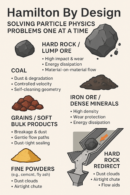
  • Chutes and hoppers exposed to high-velocity ore impact
  • Structural skids for processing equipment
  • Equipment subject to cyclic fatigue (e.g., slurry pumps, reclaimer arms)

What is Rigid Body Dynamics?

Rigid Body Dynamics (RBD) focuses on the motion of bodies under the assumption they do not deform. This tool models:

  • Position, velocity, and acceleration
  • Reaction forces at joints and actuators
  • Dynamic behaviour of moving parts and linkages
  • Contact, impact, and frictional interaction

Unlike TSA, RBD doesnโ€™t solve for stress or strain. Instead, it calculates the kinematics and kinetics of motion systems โ€” making it ideal for analysing mechanical assemblies where movement, timing, and loads are key.

Common RBD applications in mining include:

  • Stacker-reclaimer arms and boom articulation
  • Mobile equipment with hydraulic or mechanical actuators
  • Diverter chutes and gating systems
  • Rockbreaker arm kinematics
  • Conveyor take-up and tensioning systems

RBD also plays a pivotal role in process optimisation and troubleshooting โ€” helping engineers simulate how mechanisms will respond under load, ensuring operational efficiency before physical prototypes are built.


Why TSA Canโ€™t Replace RBD (and Vice Versa)

While TSA includes rigid body motion as part of the total displacement field, it is not designed for efficient or accurate motion simulation. Trying to model the dynamics of a moving mechanism in TSA can:

  • Lead to slow solve times and high computational cost
  • Produce unstable results due to unconstrained motion
  • Provide limited insight into timing, velocity, or actuation behaviour

Conversely, using RBD for structures that flex, vibrate, or wear over time wonโ€™t give you the data needed to assess material failure or fatigue.

The takeaway? Use TSA when deformation matters. Use RBD when motion matters. Use both when you need the complete picture.


Regional Applications Across Australian Mining

Hamilton By Design supports clients across Australia’s mining regions with tailored simulation services designed to meet real operational needs.

Pilbara โ€“ Iron Ore

With high-capacity iron ore operations, this region depends on large-scale materials handling systems.

  • Use RBD to simulate boom movement, slewing systems, and travel paths of stackers.
  • Use TSA to assess fatigue on booms, rail frames, and conveyor supports exposed to cyclic load.

Hamilton By Design helps model these systems efficiently, ensuring both accurate motion control and structural durability. Contact us for help simulating your Pilbara handling systems.


Kalgoorlie โ€“ Goldfields (Eastern Gold Region)

Gold operations rely on compact, high-force machinery in confined processing facilities.

  • Use TSA to simulate vibration-induced stress in equipment frames and foundations.
  • Use RBD to model diverter gates, hydraulic arms, and transport carts in processing facilities.

Whether you’re retrofitting a plant or building a new line, Hamilton By Design provides flexible support wherever you operate. Email info@hamiltonbydesign.com.au to learn more.


Hunter Valley โ€“ Coal (Thermal)

Thermal coal operations in NSW require robust, wear-resistant infrastructure.

  • RBD helps simulate automated diverters, boom stackers, and actuated gates.
  • TSA ensures the wear-prone chutes and hoppers withstand repetitive impacts.

We provide quick-turn simulations for both brownfield and greenfield projects. Get in touch to scope your simulation needs.


Bowen Basin โ€“ Coal (Metallurgical)

Queenslandโ€™s met coal operations power the global steel industry.

  • RBD enables accurate simulation of take-up systems and longwall motion.
  • TSA supports design of structural supports under repetitive and impact loading.

Our experts work with surface and underground operators, reducing risk through advanced motion and stress analysis. Request a quote at info@hamiltonbydesign.com.au.


Mount Isa โ€“ Hard Rock Mining

Mount Isaโ€™s deep and abrasive ore bodies test every piece of equipment.

  • RBD is ideal for simulating rockbreaker motion, loader paths, and mobile assets.
  • TSA provides insights into vibration effects on headframes, bins, and fixed plant.

Hamilton By Design offers full analysis support for operators in remote locations. Contact us today for tailored advice.


When to Use Both Tools Together

A real advantage emerges when RBD and TSA are used in combination:

  • RBD identifies dynamic forces and timing on moving parts
  • TSA then evaluates the structural response to those forces

For example, in a diverter chute:

  1. RBD determines the acceleration profile, impact forces, and system timing.
  2. TSA uses that input to analyse whether the chute will survive years of repeated service.

This integrated approach results in more accurate models, fewer design revisions, and significantly lower project risk.


Why Work with Hamilton By Design?

As mechanical engineering consultants with national reach, Hamilton By Design offers:

  • Combined RBD and TSA simulation capability
  • Lidar scanning and digital plant modelling
  • Experience with mining-specific assets and constraints
  • Mobile, responsive teams that bring technology to you

From site scoping to final design verification, we help our clients solve the right problem, the right way.

Have a project in mind? Reach out via our contact page or email info@hamiltonbydesign.com.au.


Conclusion: Technology That Moves With You

Rigid Body Dynamics and Transient Structural Analysis are not interchangeable โ€” they are complementary. Each method offers unique insights into how a mining system performs โ€” whether moving, flexing, vibrating, or carrying tonnes of ore.

At Hamilton By Design, we believe engineering technology should move as fast and far as our clients do. Thatโ€™s why we bring simulation, scanning, and design tools directly to you, wherever you operate across Australia.

If your system moves, simulate it with RBD. If your structure flexes, vibrates, or wears, model it with TSA. For full insight? Use both.

Let us help you design smarter, safer mining systems.

Hamilton By Design โ€“ Bringing Engineering Technology to You, Wherever You Are in Australia

Hamilton By Design logo displayed on a blue tilted rectangle with a grey gradient background


Email: sales@hamiltonbydesign.com.au

Hamilton By Design | Mechanical Drafting | Structural Drafting | 3-D Lidar Scanning

Our clients:

Name
Would you like us to arrange a phone consultation for you?
Address