Chute Blockages and Build-Up in Mining Plants

Point cloud mining infrastructure scanning connected to a 3D engineering model of a conveyor transfer chute.

Chute Blockages and Build-Up in Mining Plants | Hamilton By Design Co.

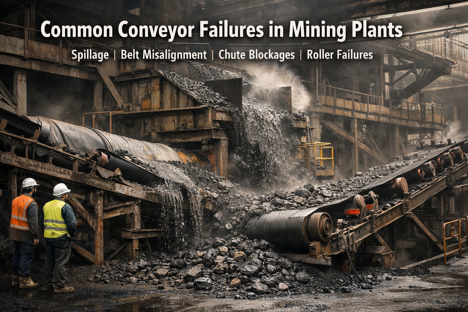
Transfer chute blockages and material build-up are some of the most common and costly problems in mining and bulk materials handling plants. A chute may look simple on paper, but in real operations it must control the flow of difficult materials under changing conditions, often within tight brownfield constraints.

When a chute begins to block, pack up, or accumulate build-up, the result is rarely limited to one small maintenance issue. Restricted flow can lead to reduced plant throughput, unplanned stoppages, excessive wear, spillage, dust, manual clean-outs, and increased shutdown risk.

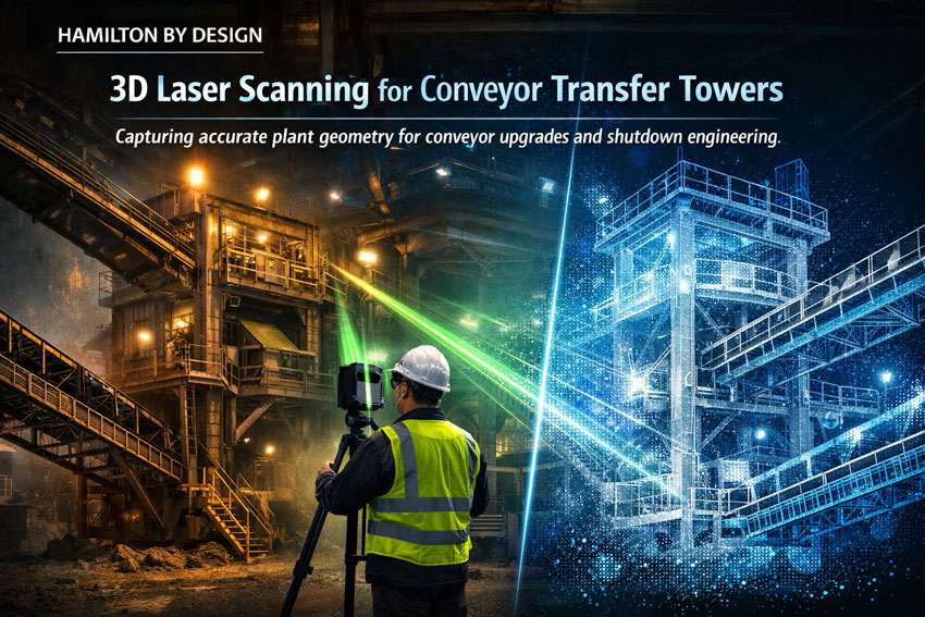
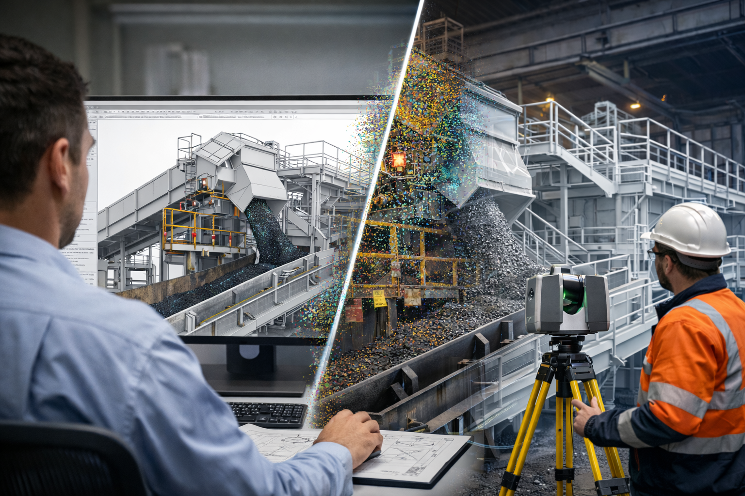
At Hamilton By Design Co., we use engineering-grade 3D laser scanning, point cloud to CAD modelling, and practical mechanical design workflows to help clients understand why existing transfer chutes are failing and how those problems can be addressed with real-world upgrade solutions.

Why Transfer Chutes Block in Real Plants

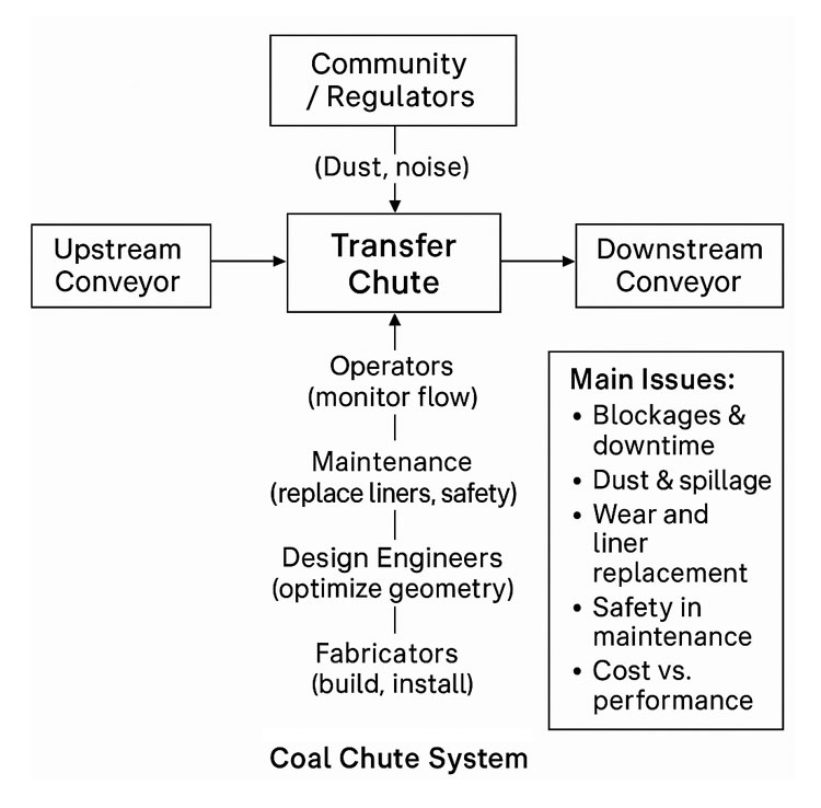
A transfer chute does more than direct material from one conveyor to another. It must manage the velocity, direction, confinement, and discharge of a bulk solid that may behave very differently from day to day.

In theory, material should flow cleanly through the chute and load the receiving belt in a controlled manner. In practice, that often does not happen.

Blockages and build-up usually develop because of one or more of the following conditions:

  • Sticky or wet material
  • High fines content
  • Poor internal chute geometry
  • Dead zones or low-velocity regions
  • Sudden changes in direction
  • Inadequate clearances
  • Existing plant modifications not shown on old drawings
  • Wear plates or liners altering the internal flow path over time

This is one of the key lessons from bulk solids handling literature and modern transfer chute simulation work: a chute should be treated as a flow system, not just fabricated steelwork. If the bulk material is not guided correctly, the chute can quickly become the source of recurring reliability issues.

Common Signs of Chute Blockages and Build-Up

Many transfer chutes continue operating badly for months or years before a proper redesign is considered. The warning signs are often already there:

Frequent clean-outs

Operators or maintenance crews may need to manually remove compacted or hung-up material from inside the chute or around discharge points.

Reduced throughput

Partial restriction can reduce the chuteโ€™s effective flow area, limiting plant performance without always producing a full blockage.

Spillage and dust

As the internal flow path changes, material may discharge poorly, generating side loading, skirt leaks, and fugitive dust.

Uneven wear

Material build-up often redirects flow, concentrating abrasion and impact into localised wear zones.

Belt loading problems

A blocked or partially restricted chute can cause off-centre loading, surging, or unstable discharge onto the receiving conveyor.

Shutdown surprises

A chute that โ€œkind of worksโ€ during operation may become a major problem during shutdown replacement or upgrade works when its actual geometry and surrounding interfaces are finally exposed.

3D laser scanner capturing a blocked mining transfer chute with a digital redesign overlay above a conveyor.

Why Old Drawings Often Do Not Tell the Full Story

One of the most common issues in brownfield mining plants is that the existing chute does not match the drawings.

Over time, sites are modified. Liners are changed. Plates are added. Wear zones are patched. Access platforms are altered. Guards move. Structural members are added or cut back. Conveyor details are updated but not always captured in the plant model.

As a result, a design team can be asked to solve a blockage problem using information that is incomplete, outdated, or simply wrong.

This is where 3D laser scanning of the existing chute and surrounding plant becomes highly valuable. Instead of relying on assumptions, the project can begin with measured site reality.

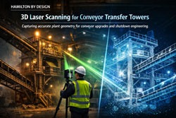
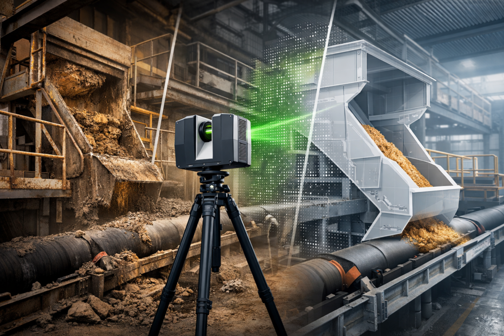
How 3D Laser Scanning Helps Diagnose Chute Problems

3D laser scanning allows existing transfer stations, chute structures, conveyors, supports, platforms, and surrounding equipment to be captured accurately as an as-built point cloud.

This gives engineers and plant teams a much better starting point for understanding blockage and build-up issues.

With a high-quality site capture, it becomes easier to:

  • Verify the true chute geometry
  • Check whether the internal chute path matches legacy drawings
  • Measure clearances around the chute and conveyors
  • Identify brownfield constraints that will affect upgrades
  • Capture surrounding steelwork, guards, supports, access ways, and services
  • Build a reliable CAD base for redesign or shutdown planning
  • Reduce fit-up risk before fabrication

For blocked or restricted transfer points, this matters because the problem is rarely isolated to one plate or one wear liner. The full transfer arrangement often needs to be understood in context.

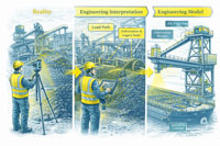
Point Cloud to CAD for Chute Upgrade Projects

Once the existing chute and surrounding transfer area have been scanned, the point cloud can be converted into useful engineering models and drawing outputs.

Depending on project requirements, this may include:

  • Existing arrangement models
  • AutoCAD model space layouts
  • General arrangement drawings
  • Section views through critical transfer zones
  • Conveyor interface checks
  • Structural and access reference models
  • Base geometry for redesign concepts

This step is important because scanning alone does not solve the problem. The value comes from turning measured site conditions into a workable engineering model that supports analysis, redesign, communication, and project delivery.

Typical Causes of Chute Build-Up

No two plants are identical, but the same broad patterns appear again and again in mining and bulk materials handling systems.

Poor chute geometry

Flat ledges, abrupt transitions, internal obstructions, and shallow flow surfaces can create low-energy zones where material begins to hang up.

Material variability

A chute may perform reasonably with dry product but fail badly when moisture, fines content, or feed consistency changes.

Wear changing the flow path

As liners wear, the material trajectory and internal contact pattern can change. In some cases, past repairs can unintentionally make the problem worse.

Inadequate discharge control

If the material is not being guided cleanly through the chute, unstable flow can create recirculation, impact concentration, and inconsistent discharge onto the receiving belt.

Brownfield constraints

Legacy chute geometry is often shaped by what could fit at the time, not by what offered the best flow. This is especially true where upgrades have been added over many years.

A Practical Engineering Approach

At Hamilton By Design Co., we see chute blockage problems as both a materials handling issue and a brownfield engineering issue.

That means the practical workflow is often:

1. Capture the existing transfer area

We scan the chute, conveyors, structure, and surrounding plant to create an accurate as-built record.

2. Build the engineering base model

We convert the point cloud into usable CAD references for design, review, and planning.

3. Understand the real constraint

We assess what the current chute is doing, what clearances exist, and where the upgrade risks are likely to sit.

4. Support redesign and upgrade works

The as-built data can then be used to support mechanical design, chute modification concepts, shutdown planning, and fabrication fit-up.

This practical approach is especially useful where the site is already experiencing recurring clean-outs, ongoing maintenance cost, or uncertainty around existing geometry.

Where This Applies

This type of work is relevant across a wide range of bulk materials handling environments, including:

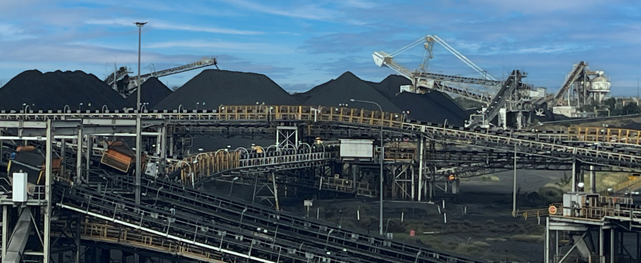
  • Coal handling plants
  • Hard rock mining operations
  • Quarry transfer systems
  • Materials handling conveyors
  • Process plant transfer stations
  • Brownfield chute replacement projects

Why This Matters

Transfer chutes are often underestimated. A poorly performing chute can quietly create lost production, repeated maintenance, high cleanup cost, and shutdown complications for years.

The real lesson from bulk solids handling practice is that a chute should not be designed or upgraded as just a fabricated box. It must be understood as part of a controlled material flow system, operating within the real physical constraints of the plant.

When those constraints are not fully understood, blockage and build-up problems tend to repeat.

That is why 3D laser scanning, point cloud to CAD modelling, and measured as-built engineering data are such valuable first steps in solving restricted or unreliable transfer points.

3D LiDAR scanning and 3D modelling service button โ€” laser scanner capturing a point cloud for engineering and CAD modelling
Mechanical engineering services

Need Support with an Existing Chute Problem?

If your site is dealing with chute blockages, material build-up, inaccurate plant drawings, or shutdown upgrade risk, Hamilton By Design Co. can help capture the existing conditions and provide an engineering-ready base for the next stage of the project.

Hamilton By Design logo displayed on a blue tilted rectangle with a grey gradient background

We support mining and industrial clients with:

  • 3D laser scanning of existing plant
  • Point cloud to CAD conversion
  • Existing condition modelling
  • Brownfield upgrade support
  • Chute and transfer station design workflows

Contact Hamilton By Design Co. to discuss your existing chute, transfer point, or scanning requirement.

Name
Would you like us to arrange a phone consultation for you?
Address

Our clients

CHPP Engineering title graphic featuring bold white text reading "CHPP Engineering" centred on a blue rounded rectangle background.
Pipework Drafting title graphic featuring bold white text reading "Pipework Drafting" centred on a blue rounded rectangle background.
3D LiDAR Scanning for Engineering Projects title graphic featuring bold white text on a blue rounded rectangle background.
3D CAD Modelling Australia service banner for Hamilton By Design

Why Conveyor Reliability Matters in Mining

Conveyor system failure in a mining processing plant with spillage and damaged rollers.

Conveyor systems are the backbone of most mining operations. They move thousands of tonnes of ore every hour between crushers, processing plants, stockpiles, and load-out facilities.

When a conveyor fails, the impact can be immediate and costly. Production stops, plant operators must respond quickly, and maintenance teams are forced to work under pressure to restore operations.

Understanding the common causes of conveyor failures in mining plants is essential for improving plant reliability and reducing unplanned downtime.


1. Conveyor Belt Damage

One of the most frequent conveyor failures in mining is damage to the conveyor belt itself.

Typical causes include:

  • impact from large rocks at transfer points
  • sharp materials cutting the belt
  • misaligned loading onto the receiving belt
  • worn or damaged idlers

When belts become damaged, operations may experience:

  • belt tears
  • belt mistracking
  • material spillage

Over time this leads to reduced production efficiency and increased maintenance costs.

Proper chute design and impact control can significantly reduce belt damage.


2. Transfer Chute Blockages

Transfer chutes are often the most problematic areas in materials handling systems.

Poorly designed transfer chutes can cause:

  • material build-up
  • flow restrictions
  • complete blockages

These problems are especially common when handling:

  • wet ore
  • sticky materials
  • fine particles

When chutes block, the upstream conveyors continue feeding material until the system trips or operators intervene.

This can quickly escalate into major plant disruptions.


3. Conveyor Misalignment

Another common maintenance issue is belt misalignment.

Misalignment occurs when the belt does not track correctly along the conveyor structure.

Common causes include:

  • uneven loading at transfer points
  • worn idlers
  • structural movement or damage
  • incorrect installation

When conveyors run out of alignment they can cause:

  • edge damage to belts
  • excessive wear on idlers
  • safety hazards from material spillage

Regular inspection and proper transfer design can reduce this risk.


4. Structural Fatigue and Failure

Mining conveyors operate in harsh environments and are subjected to constant vibration and loading.

Over time this can lead to structural issues such as:

  • cracked steel structures
  • damaged conveyor supports
  • fatigue in transfer chute frames

These failures may not be immediately visible but can develop gradually over years of operation.

Engineering inspections and accurate plant modelling can help identify these risks before they become critical failures.


5. Wear in Materials Handling Equipment

Mining materials are often highly abrasive.

Components that commonly experience heavy wear include:

  • chute liners
  • skirt plates
  • idlers
  • pulley lagging

If these parts are not replaced in time, they can lead to larger system failures.

Preventative maintenance programs help ensure that wear components are replaced before reliability issues develop.


Improving Plant Reliability Through Engineering

Reducing conveyor failures in mining plants requires a combination of:

  • good engineering design
  • proper maintenance practices
  • accurate understanding of existing plant infrastructure

Modern engineering techniques such as 3D laser scanning and digital modelling allow engineers to capture the true geometry of operating plants.

This helps identify problems such as:

  • poor transfer geometry
  • structural clashes
  • restricted maintenance access

These issues can then be addressed before they lead to operational failures.

You can learn more about mining mechanical engineering design services here:


Preparing Conveyor Upgrades During Shutdowns

Many conveyor upgrades and maintenance projects are performed during planned plant shutdowns.

Because shutdown windows are limited, careful preparation is essential.

Engineering preparation may include:

  • capturing existing plant conditions
  • producing detailed engineering models
  • planning structural modifications
  • preparing fabrication drawings

Proper shutdown planning reduces the risk of installation delays and ensures that maintenance work is completed safely.

Learn more about shutdown preparation here:


Using Digital Engineering to Reduce Risk

Digital engineering tools now allow mining operations to develop accurate digital models of their processing plants.

These models help engineers:

  • analyse conveyor systems
  • redesign transfer chutes
  • identify potential failure points
  • plan upgrades with confidence

By using digital engineering models, mining companies can significantly reduce the risk of plant downtime and improve overall reliability.

More information on this approach can be found here:


Final Thoughts

Conveyor systems are critical to the performance of mining plants, but they are also one of the most common sources of operational failure.

By understanding the causes of conveyor failures in mining, operations teams can focus on improving:

  • transfer chute design
  • maintenance practices
  • plant engineering preparation

Through proper engineering and planning, mining companies can improve reliability, reduce downtime, and ensure that their materials handling systems continue to operate safely and efficiently.

3D LiDAR scanning and 3D modelling service button โ€” laser scanner capturing a point cloud for engineering and CAD modelling
Mechanical engineering services
Name
Would you like us to arrange a phone consultation for you?
Address
CHPP Engineering title graphic featuring bold white text reading "CHPP Engineering" centred on a blue rounded rectangle background.
Pipework Drafting title graphic featuring bold white text reading "Pipework Drafting" centred on a blue rounded rectangle background.
3D LiDAR Scanning for Engineering Projects title graphic featuring bold white text on a blue rounded rectangle background.
3D CAD Modelling Australia service banner for Hamilton By Design

3D Laser Scanning for Conveyor Transfer Towers

3D laser scanning of a mining conveyor transfer tower capturing point cloud data for engineering modelling.

Conveyor transfer towers are critical components within mining and bulk material handling operations. These structures control the movement of material between conveyors and often contain complex arrangements of chutes, structural steel, maintenance platforms, and access walkways.

Over time, many transfer towers are modified as production requirements change. Equipment upgrades, chute redesigns, and maintenance improvements can result in plant infrastructure that no longer matches the original engineering drawings.

For engineers planning upgrades or maintenance projects, accurate existing condition data is essential. One of the most effective ways to capture this information is through 3D laser scanning.

At Hamilton By Design, engineering-grade scanning is used to capture precise geometry of conveyor transfer towers and surrounding plant infrastructure. This data can then be converted into accurate digital models used for mechanical design, plant upgrades, and engineering analysis.

Engineer performing LiDAR scanning of a conveyor transfer tower in a mining processing plant.

Learn more about our engineering scanning capabilities here:
๐Ÿ‘‰ https://www.hamiltonbydesign.com.au/home/engineering-services/3d-laser-scanning/


Why Conveyor Transfer Towers Are Difficult to Measure

Transfer towers are often some of the most complex areas within a processing plant. They typically contain multiple systems operating within a confined structure including conveyors, transfer chutes, structural supports, and maintenance platforms.

These environments can include:

โ€ข multiple conveyors entering and exiting the structure
โ€ข chute systems with wear liners
โ€ข structural steel frames and supports
โ€ข maintenance walkways and access platforms
โ€ข dust control and service equipment

Because of the tight layout and elevation changes within these structures, traditional measurement methods can be slow and prone to error.

In many facilities, the original engineering drawings may also be outdated due to years of plant modifications.

Accurate measurement is therefore essential when designing upgrades or modifications to conveyor transfer systems.


Using 3D Laser Scanning to Capture Transfer Tower Geometry

Engineering-grade 3D laser scanning uses LiDAR technology to capture millions of spatial measurements of plant infrastructure.

The resulting dataset forms a point cloud model representing the exact geometry of conveyors, structural steel, chutes, and surrounding plant equipment.

This digital model allows engineers to analyse plant layouts and develop accurate engineering designs before physical work begins.

Laser scanning provides several advantages when working in conveyor transfer towers.

Accurate Existing Conditions

Scanning captures the true geometry of plant infrastructure, allowing engineers to design modifications based on reliable data rather than outdated drawings.

Improved Design Planning

Digital models generated from scan data allow engineers to verify clearances and identify potential clashes before installation.

Reduced Shutdown Risk

Engineering teams can plan installation work more effectively using digital models created from scan data.

Faster Data Capture

Laser scanning can capture complex structures quickly compared with traditional measurement methods.


3D Scanning for Mining Shutdown Projects

Many conveyor transfer tower upgrades are performed during planned mining shutdowns, where engineering teams must complete inspections, modifications, and installations within tight timeframes.

Laser scanning provides a fast and reliable way to capture accurate plant geometry before shutdown work begins. Engineers can then analyse the digital model and develop upgrade designs in advance.

This approach reduces the risk of unexpected installation issues during shutdown periods.

You can learn more about scanning applications during plant shutdowns here:

๐Ÿ‘‰ https://www.hamiltonbydesign.com.au/home/engineering-grade-3d-laser-scanning-mining-industrial/3d-scanning-mining-shutdown-projects/


From Laser Scan to Engineering Model

The laser scanning workflow for conveyor transfer towers typically follows a structured process.

  1. Planning scan locations within the transfer tower
  2. Capturing plant geometry using LiDAR scanners
  3. Registering scan positions to create a unified point cloud
  4. Extracting geometry from the point cloud dataset
  5. Creating engineering CAD models for design analysis

These models allow engineers to analyse plant infrastructure and design upgrade solutions with greater confidence.


Reverse Engineering Conveyor Infrastructure

In many mining plants, original equipment drawings are missing or no longer reflect the current infrastructure. In these cases, laser scanning can be used to reverse engineer existing equipment and structures.

By capturing the geometry of conveyors, chutes, and supporting structures, engineers can recreate accurate CAD models used for redesign, replacement components, or plant upgrades.

Hamilton By Design provides reverse engineering services using high-accuracy scanning technology.

Learn more about this process here:

๐Ÿ‘‰ https://www.hamiltonbydesign.com.au/reverse-engineer-3d-scanning/


Digital Engineering for Conveyor Transfer Towers

Digital models created from laser scanning allow engineers to analyse plant infrastructure in a controlled environment before work begins on site.

These models support engineering tasks such as:

โ€ข chute design and optimisation
โ€ข conveyor upgrade planning
โ€ข structural modifications
โ€ข clash detection and layout verification
โ€ข maintenance planning and documentation

For mining operations, this approach improves the reliability of plant upgrade projects and reduces engineering risk.


Engineering Support from Hamilton By Design

Hamilton By Design provides engineering-led 3D laser scanning and mechanical design services supporting mining and industrial infrastructure projects across Australia.

Our services include:

โ€ข conveyor transfer tower scanning
โ€ข plant upgrade engineering
โ€ข mechanical design and modelling
โ€ข reverse engineering of plant infrastructure
โ€ข digital engineering models and inspections

By combining scanning technology with engineering expertise, we help mining and industrial clients capture accurate plant geometry and convert it into practical engineering solutions.


Hamilton By Design logo displayed on a blue tilted rectangle with a grey gradient background

Learn More About Engineering-Grade Laser Scanning

For a full overview of engineering-grade laser scanning and its applications in mining and industrial plants, visit:

๐Ÿ‘‰ https://www.hamiltonbydesign.com.au/home/engineering-grade-3d-laser-scanning-mining-industrial/


Anthony Hamilton
Principal Engineer
Hamilton By Design


Name
Would you like us to arrange a phone consultation for you?
Address

3D CAD Modelling Australia service banner for Hamilton By Design

3D Laser Scanning in Parramatta: Safer Conveyor Design with Engineering-Grade Accuracy

Engineering-grade LiDAR scanning of a brownfield industrial asset, showing the progression from site capture and point cloud interpretation to a fabrication-ready engineering model.

3D Laser Scanning for Conveyor Design & Safe Engineering in Parramatta

Parramatta continues to grow as a major industrial and infrastructure hub for Western Sydney. With ageing plant, frequent upgrades, and tighter safety expectations, many facilities are now turning to engineering-grade 3D laser scanning to improve the way conveyor systems and material handling equipment are designed, modified, and maintained.

At Hamilton By Design, we use high-accuracy LiDAR scanning to capture existing conditions and convert them into precise 3D models that engineers, designers, and maintenance teams can rely on โ€” before anyone picks up a spanner or starts cutting steel.

Why Conveyor Systems Are High-Risk Assets

Conveyors are involved in a significant number of serious workplace incidents across Australia. Common contributors include:

  • Inadequate guarding and access control
  • Poor visibility of nip points and transfer zones
  • Modifications made without updated drawings
  • Space constraints forcing unsafe maintenance practices

In many older facilities around Parramatta, conveyors have been extended, rerouted, or repaired multiple times over decades โ€” often without accurate as-built documentation. This creates real risk when new upgrades or safety improvements are planned.

Without reliable spatial data, design decisions are often made on assumptions, outdated drawings, or rough site measurements.

Engineering-Grade Scanning: Not Just โ€œPretty Picturesโ€

Not all 3D scans are suitable for engineering or safety-critical work.

We use engineering-grade LiDAR scanning capable of delivering dimensional accuracy of approximately ยฑ2 mm over 70 metres, which allows us to:

  • Model conveyor structures, walkways, guards, and transfer stations
  • Detect clashes before fabrication
  • Verify compliance with safe access and guarding requirements
  • Support certified engineering design and sign-off

The resulting point cloud and CAD models become the foundation for proper conveyor design, safety reviews, and fabrication drawings.

This is critical when safe design obligations must be demonstrated under WHS legislation.


Industrial machine guards including a guarded conveyor, fenced robotic cell, and covered belt drive system

Supporting Safe Design from Concept to Commissioning

Safe Design is not just about guarding at the end of a project โ€” it starts at the design stage.

By scanning your existing plant, we can support:

  • Risk assessments using accurate spatial context
  • Redesign of transfer points and access platforms
  • Guarding upgrades that actually fit the site
  • Maintenance access improvements without production impact

Because models are generated from real geometry, engineers can confidently design modifications knowing they will physically fit when installed.

This reduces shutdown risk, rework, and last-minute site changes โ€” all common contributors to project delays and safety incidents.

Learning from Industry Incidents โ€” and Preventing the Next One

Many conveyor-related incidents share similar root causes:

  • Poor access for cleaning or inspection
  • Unplanned modifications
  • Incomplete hazard identification during design
  • Reliance on legacy drawings that no longer match reality

3D scanning allows hazards to be identified early and reviewed by multiple stakeholders โ€” engineering, safety, operations, and maintenance โ€” using the same accurate model.

It also creates a permanent digital record of the asset at a point in time, which is invaluable for:

  • Incident investigations
  • Compliance documentation
  • Future upgrade planning

In high-risk environments, accurate data is not a luxury โ€” it is a control measure.

Local Scanning and Engineering Support in Parramatta

Hamilton By Design provides on-site 3D scanning and engineering services across Parramatta and Western Sydney, supporting:

  • Conveyor upgrades and replacements
  • Safety improvement projects
  • Plant expansions and brownfield modifications
  • Fabrication and installation planning

Our team is engineering-led, meaning scanning is not treated as a standalone service โ€” it is directly integrated into mechanical design, drafting, and project delivery.

We also provide fabrication-ready drawings and can support workshops with shop details derived directly from scan-based models.


Hamilton By Design logo displayed on a blue tilted rectangle with a grey gradient background

3D LiDAR scanning and 3D modelling service button โ€” laser scanner capturing a point cloud for engineering and CAD modelling
Mechanical engineering services

From Point Cloud to Practical Outcomes

3D scanning is only valuable if it leads to better decisions on the ground.

Our workflow typically includes:

  1. On-site LiDAR scanning with minimal disruption to operations
  2. Registration and cleaning of point cloud data
  3. Conversion into CAD models suitable for engineering design
  4. Design development, safety reviews, and fabrication drawings

This ensures your project is driven by real-world data โ€” not assumptions.

Name
Would you like us to arrange a phone consultation for you?
Address

Related Sydney Services

Hamilton By Design provides engineering-led 3D scanning, LiDAR scanning, mechanical engineering and digital engineering services throughout Sydney and Greater Sydney.

Explore our related Sydney services:


  • 3D Scanning Sydney โ€“ Engineering-grade terrestrial laser scanning, as-built surveys and point cloud capture for industrial, infrastructure and commercial projects.
  • Reality Capture Sydney โ€“ High-accuracy reality capture, digital twins, asset documentation and engineering-grade site verification.
  • Scan to CAD Sydney โ€“ Convert point cloud data into AutoCAD, SolidWorks, Inventor and other engineering-ready CAD deliverables.
  • Point Cloud Modelling Sydney โ€“ Engineering-grade point cloud processing, clash detection, as-built verification and 3D modelling.
  • Mechanical Engineering Sydney โ€“ Mechanical design, plant upgrades, materials handling systems, conveyors, chutes, platforms and engineering support.
  • Structural Drafting Sydney โ€“ Structural steel drafting, fabrication drawings, GA drawings, workshop detailing and as-built documentation.

Hamilton By Design supports projects throughout Sydney CBD, Parramatta, Liverpool, Penrith, Blacktown, Chatswood, Alexandria, Mascot, Newcastle and the Central Coast.


Blue banner graphic displaying the text "Point Cloud to CAD - Australia" in large white lettering, representing point cloud processing, scan-to-CAD conversion and digital engineering services across Australia.
Blue banner graphic displaying the text "Scan to CAD Sydney" in large white lettering, representing engineering-led point cloud to CAD conversion, LiDAR scanning and digital engineering services in Sydney.
Blue banner graphic displaying the text "Reality Capture Sydney - CBD" in large white lettering, representing engineering-led reality capture, LiDAR scanning and digital engineering services within Sydney CBD commercial buildings and infrastructure.

Coal Chute Design

Coal handling and processing facility with multiple conveyors, stockpiles of coal, and stacking-reclaiming machinery operating under a blue sky

A Systems Engineering Approach for Reliable Coal Handling

In coal mining operations, transfer chutes play a deceptively small role with disproportionately large impacts. They sit quietly between conveyors, crushers, and stockpiles, directing tonnes of coal every hour. Yet when a chute is poorly designed or not maintained, the whole coal handling system suffers: blockages stop production, dust creates safety and environmental hazards, and worn liners demand costly maintenance shutdowns.

At Hamilton by Design, we believe coal chute design should be treated not as a piece of steelwork, but as a systems engineering challenge. By applying systems thinking, we connect stakeholder requirements, material behaviour, environmental factors, and lifecycle performance into a holistic design approach that delivers long-term value for mining operations in the Hunter Valley and beyond.


Coal Chutes in the Mining Value Chain

Coal chutes form the links in a chain of bulk material handling equipment:

  • ROM bins and crushers feed coal into the system.
  • Conveyors carry coal across site, often over long distances.
  • Transfer chutes guide coal between conveyors or onto stockpiles.
  • Load-out stations deliver coal to trains or ports for export.

Although they are small compared to conveyors or crushers, coal chutes are often where problems first appear. A well-designed chute keeps coal flowing consistently; a poorly designed one causes buildup, spillage, dust emissions, and accelerated wear. Thatโ€™s why leading operators now see chute design as a critical system integration problem rather than just a fabrication task.

Flow diagram of a coal chute system showing upstream and downstream conveyors, the transfer chute, stakeholder interactions, and main issues such as blockages, dust, wear, maintenance safety, and cost versus performance

Systems Engineering in Coal Chute Design

Systems engineering is the discipline of managing complexity in engineering projects. It recognises that every component is part of a bigger system, with interdependencies and trade-offs. Applying this mindset to coal chute design ensures that each chute is considered not in isolation, but as part of the broader coal handling plant.

1. Requirements Analysis

The first step is gathering and analysing stakeholder and system requirements:

  • Throughput capacity: e.g. handling 4,000 tonnes per hour of coal.
  • Material properties: coal size distribution, moisture content, abrasiveness, stickiness.
  • Safety requirements: compliance with AS/NZS 4024 conveyor safety standards, confined space entry protocols, guarding, and interlocks.
  • Environmental compliance: dust, noise, and spillage limits.
  • Maintenance objectives: target liner life (e.g. 6 months), maximum downtime per liner change (e.g. 30 minutes with two workers).

A structured requirements phase reduces the risk of costly redesign later in the project.


2. System Design and Integration

Once requirements are defined, the design process considers how the chute integrates into the coal handling system:

  • Flow optimisation using DEM: Discrete Element Modelling allows engineers to simulate coal particle behaviour, test different geometries, and reduce blockages before steel is ever cut.
  • Dust control strategies: designing chutes with enclosures, sprays, and extraction ports to minimise airborne dust.
  • Wear management: predicting wear zones, selecting suitable liner materials (ceramic, Bisplate, rubber composites), and ensuring easy access for replacement.
  • Structural and safety design: ensuring the chute can withstand dynamic loads, vibration, and impact, while providing safe access platforms and guarding.
  • Interfaces with conveyors and crushers: alignment, skirt seals, trip circuits, and integration with PLC/SCADA control systems.

By treating the chute as a subsystem with multiple interfaces, designers avoid the โ€œbolt-onโ€ mentality that often leads to operational headaches.


3. Verification and Validation

The systems engineering V-model reminds us that every requirement must be verified and validated:

  • Component verification: weld inspections, liner hardness testing, nozzle spray checks.
  • Subsystem verification: chute section fit-up, guard gap measurements, coating checks.
  • Integration testing: conveyor-chute alignment, PLC spray interlocks, trip circuits.
  • System validation: commissioning with live coal flow, dust monitoring against limits, maintainability time trials for liner change.

By linking requirements directly to tests in a traceability matrix, operators can be confident that the chute is not only built to spec, but proven in operation.


Lifecycle Engineering: Beyond Installation

Good chute design doesnโ€™t stop at commissioning. A lifecycle engineering mindset ensures the chute continues to deliver performance over years of operation.

  • Maintainability: modular liners, captive fasteners, hinged access doors, and clear procedures reduce downtime and improve worker safety.
  • Reliability: DEM-informed designs and wear-resistant materials reduce the frequency of blockages and rebuilds.
  • Sustainability: dust suppression and enclosure strategies reduce environmental impact and support community and regulatory compliance.
  • Continuous improvement: feedback loops from operators and maintenance teams feed into the next design iteration, closing the systems engineering cycle.

A Rich Picture of Coal Chute Complexity

Visualising the coal chute system as a rich picture reveals its complexity:

  • Operators monitoring flow from control rooms.
  • Maintenance crews working in confined spaces, replacing liners.
  • Design engineers using DEM simulations to model coal flow.
  • Fabricators welding heavy plate sections on site.
  • Environmental officers measuring dust levels near transfer points.
  • Regulators and community monitoring compliance.

This web of relationships shows why coal chute design benefits from systems thinking. No single stakeholder sees the whole pictureโ€”but systems engineering does.


Benefits of a Systems Engineering Approach

When coal chute design is guided by systems engineering principles, operators gain:

  • Higher reliability: smoother coal flow with fewer blockages.
  • Lower maintenance costs: liners that last longer and can be swapped quickly.
  • Improved compliance: dust, spillage, and safety issues designed out, not patched later.
  • Lifecycle value: less unplanned downtime and a lower total cost of ownership.

In short, systems engineering transforms coal chutes from weak links into strong connectors in the mining value chain.


Case Study: Hunter Valley Context

In the Hunter Valley, coal mines have long struggled with transfer chute problems. Companies like T.W. Woods, Chute Technology, HIC Services, and TUNRA Bulk Solids have all demonstrated the value of combining local fabrication expertise with advanced design tools. Hamilton by Design builds on this ecosystem by applying structured systems engineering methods, ensuring each chute project balances performance, safety, cost, and sustainability.


Conclusion

Coal chute design might seem like a small detail, but in mining, details matter. When transfer chutes fail, production stops. By applying systems engineering principlesโ€”from requirements analysis and DEM modelling to verification, lifecycle planning, and continuous improvementโ€”we can design coal chutes that are reliable, maintainable, and compliant.

At Hamilton by Design, we believe in tackling these challenges with a systems mindset, delivering solutions that stand up to the realities of coal mining.


Are you struggling with coal chute blockages, dust, or costly downtime in your coal handling system?

Hamilton By Design logo displayed on a blue tilted rectangle with a grey gradient background

Contact Hamilton by Design today and discover how our systems engineering expertise in coal chute design can optimise your mining operations for performance, safety, and sustainability.

Mechanical Engineering | Structural Engineering

Mechanical Drafting | Structural Drafting

3D CAD Modelling | 3D Scanning

Chute Design

SolidWorks Contractors in Australia

Hamilton By Design โ€“ Blog

Our clients:

Name
Would you like us to arrange a phone consultation for you?
Address
Finite Element Analysis (FEA) engineering simulation button
Mechanical engineering services