SolidWorks Drafting Services Northern Territory | Engineering-Led CAD Support

Engineering-led SolidWorks drafting in the Northern Territory with 25 years of Hamilton By Design experience

SolidWorks Drafting Services Northern Territory | Engineer-Led CAD Support

Engineering-Led SolidWorks Drafting Services in the Northern Territory

In the Northern Territory (NT) โ€” where industrial projects, remote operations, and infrastructure upgrades demand accuracy and accountability โ€” SolidWorks drafting is more than just โ€œCAD work.โ€ It must reflect real site conditions, installation constraints, and fabrication realities to avoid costly rework and downtime.

At Hamilton By Design, we provide SolidWorks drafting services in the Northern Territory that are:

  • Engineer-led
  • Fabrication-aware
  • Aligned with real industrial outcomes
  • Deliverable for fabrication and installation readiness

We donโ€™t just produce drawings โ€” we deliver engineered documentation that works on site.

SolidWorks 30 years cube with Hamilton By Design highlighting 25 years of SolidWorks use in the Northern Territory

Who Uses Our SolidWorks Drafting Services in the NT

Clients contact us when they need to:

  • Outsource SolidWorks drafting for mechanical systems or assemblies
  • Update or replace outdated drawings that no longer match site conditions
  • Add drafting capacity without sacrificing engineering quality
  • Support brownfield upgrades, process modifications, and shutdown planning
  • Integrate reverse engineering / scan-to-model deliverables into formal SolidWorks drawings

Many Northern Territory operators start with โ€œI need to hire a SolidWorks drafterโ€ โ€” and quickly realise they also need engineering judgement behind the drafting work.


Why Engineering-Led SolidWorks Drafting Matters in the NT

SolidWorks is a powerful CAD platform โ€” but the value of drafting depends on the engineering context behind it.

Hamilton By Designโ€™s drafting combines:

  • Engineering knowledge applied to drafting decisions
  • Understanding of fabrication constraints (welds, tolerances, access)
  • Installation and erection context
  • Integration with as-built conditions
  • Documentation compliant with project and statutory requirements

This reduces rework, decreases fit-up risk, and better supports tendering and construction outcomes for NT industry clients.


Northern Territory SolidWorks Drafting Services We Provide

Our NT SolidWorks drafting support includes:

  • Mechanical part and assembly drafting
  • Fabrication-ready workshop drawings
  • Structural support and steel detailing
  • Reverse-engineered part drawings
  • As-built model integration (from scans or legacy assets)
  • Drawing updates based on site verification data

All drafting deliverables are created with fabrication and installation readiness in mind, not just geometric accuracy.


Engineering Integration or Secondment Support

For clients needing embedded drafting support, we also offer engineering-led secondment services.

Learn more here:
https://www.hamiltonbydesign.com.au/home/secondment-services/

This is ideal for:

  • Fabricators needing additional drafting capacity
  • Project teams with peak demand
  • Operations requiring close, day-to-day collaboration

Our secondees arenโ€™t just drafters โ€” they bring engineering insight that improves drawing quality and project outcomes.


Industries in the Northern Territory That Benefit

We work with clients across the Territory, including:

  • Mining and processing facilities
  • Ports and logistics infrastructure
  • Utilities and remote infrastructure operators
  • Manufacturing and mechanical services
  • Shutdown, maintenance, and upgrade projects

Whether you are based in Darwin, Katherine, Alice Springs, or remote NT operations, we can support your SolidWorks drafting and technical documentation needs.


Our clients:


How We Differ from Drafting-Only Providers

Many drafting vendors treat SolidWorks as a tool only.

At Hamilton By Design, we combine it with engineering judgment:

  • Ownership of outcome, not just deliverables
  • Fabrication and installation practicality, not just pretty drawings
  • Coordination with site reality, not digital assumptions
  • Support through construction and inspection, not just closure

This is what sets us apart in the Northern Territory market.

Hamilton By Design logo displayed on a blue tilted rectangle with a grey gradient background

3D LiDAR scanning and 3D modelling service button โ€” laser scanner capturing a point cloud for engineering and CAD modelling
Mechanical engineering services

3D Scanning

3D Scanning Darwin


Discuss Your SolidWorks Drafting Project

If youโ€™re considering outsourcing SolidWorks drafting โ€” or you need engineering-led drafting support โ€” early engagement can reduce risk and improve delivery certainty.

Talk to us about your Northern Territory project and weโ€™ll help determine whether project-based drafting or secondment support is right for you.

Use the contact form below to start the conversation.

Name
Would you like us to arrange a phone consultation for you?
Address

Drafting Capacity for Todayโ€™s Projects: An Integrated Scan โ†’ Model โ†’ Detail โ†’ Check Workflow

Drafting Capacity for Todayโ€™s Projects | Engineering-Led Documentation

Engineering and construction projects are increasingly delivered under compressed timeframes, constrained resources, and heightened compliance expectations. In this environment, access to reliable drafting capacityโ€”supported by robust processesโ€”is critical to maintaining quality and reducing project risk.

Hamilton By Design provides experienced drafting capacity, available for short-term support or longer-term secondment, delivered within a structured scan โ†’ model โ†’ detail โ†’ check workflow that aligns documentation with real-world conditions and engineering intent.


Drafting capacity aligned with contemporary project demands

Modern projects often require drafting support that can scale quickly to address:

  • Peak workloads during design development or shutdown preparation
  • Short-term resourcing gaps within engineering teams
  • Documentation demands driven by upgrades, modifications, or compliance works
  • Brownfield environments where existing information is incomplete or unreliable

In these situations, drafting capacity must be more than transactional. It must integrate with engineering workflows and reflect current site conditions.


Scan: establishing an accurate technical baseline

Where existing drawings cannot be relied upon, accurate documentation begins with engineering-grade reality capture.

Our team utilises 3D laser scanning to establish a defensible geometric baseline of existing assets. This approach supports drafting activities by ensuring that models and drawings are developed from verified site data, rather than assumptions or legacy documentation.


Model: structured CAD developed for engineering use

Scan data is translated into purpose-built CAD models, developed to suit the intended engineering and documentation outcomes. Models are structured with appropriate datums, tolerances, and levels of detail to support:

  • Engineering assessment and design coordination
  • Structural and mechanical detailing
  • As-built documentation and future modification

This modelling stage ensures drafting activities are grounded in usable, engineering-aligned data.


Detail: producing clear, buildable documentation

Drafting output remains one of the most critical interfaces between design and construction.

From verified models, our draftspersons produce clear, fabrication-ready drawings that communicate engineering intent accurately and unambiguously. Documentation is prepared with consideration for:

  • Constructability and sequencing
  • Fabrication practicality
  • Coordination between disciplines
  • Alignment with relevant Australian Standards

The emphasis is on documentation that can be confidently issued to site.


Check: verification as a formal step, not an afterthought

Before issue, drawings and models are subject to structured review to confirm:

  • Consistency with scan data and models
  • Coordination across views and drawing sets
  • Technical clarity and buildability

This checking step reduces the likelihood of downstream rework and supports defensible documentation outcomes.


Why integrated drafting capacity matters

When drafting is separated from scanning, modelling, or checking, risk is introduced at each handover.

An integrated scan โ†’ model โ†’ detail โ†’ check workflow:

  • Improves documentation reliability
  • Reduces errors caused by assumptions
  • Supports compliance and verification
  • Enhances confidence during fabrication and construction

This approach is particularly effective for existing assets, industrial facilities, and brownfield upgrades.


Flexible drafting support and secondment

Hamilton By Designโ€™s drafting capacity can be provided as:

  • Short-term drafting support
  • Longer-term secondment within client teams
  • Targeted assistance during high-demand project phases

Drafting support is delivered within an engineering-led environment, ensuring alignment between documentation and technical intent.

To learn more about flexible resourcing options, visit our Secondment Services page:
๐Ÿ‘‰ https://www.hamiltonbydesign.com.au/home/secondment-services/


Hamilton By Design logo displayed on a blue tilted rectangle with a grey gradient background
3D LiDAR scanning and 3D modelling service button โ€” laser scanner capturing a point cloud for engineering and CAD modelling
Mechanical engineering services

Conclusion

As project complexity and delivery pressures continue to increase, drafting capacity must be current, integrated, and accountable.

By providing experienced draftspersons supported by a structured scan โ†’ model โ†’ detail โ†’ check workflow, Hamilton By Design enables project teams to scale documentation capability without compromising accuracy, buildability, or engineering quality.

Name
Would you like us to arrange a phone consultation for you?
Address
Finite Element Analysis (FEA) engineering simulation button
Mechanical engineering services

As-Built Documentation

As-Built Documentation | Why Accurate Records Matter in Engineering


When drawings donโ€™t reflect what is actually installed on site, projects are exposed to design errors, safety risks, rework, and compliance issues. In industrial, mining, power, and construction environments, relying on outdated or assumed information can quickly lead to costly mistakes.

At Hamilton By Design, as-built documentation is treated as an engineering deliverable, not an administrative afterthought.


What is as-built documentation?

As-built documentation records the true, physical condition of an asset after construction, modification, or installation.

This can include:

  • As-built drawings (plans, sections, elevations)
  • As-built CAD models
  • Verified dimensions and interfaces
  • Documented deviations from original design
  • Digital records suitable for future upgrades and maintenance

Unlike โ€œdesign intentโ€ drawings, as-built documentation reflects what exists in reality, not what was originally planned.


Why poor as-built documentation causes problems

Many facilities operate with drawings that are:

  • Outdated
  • Incomplete
  • Never updated after modifications
  • Based on assumptions or manual measurements

This creates risk when:

  • Designing upgrades or tie-ins
  • Replacing equipment
  • Assessing compliance with Australian Standards
  • Planning shutdowns or maintenance works

Common outcomes include:

  • Components that donโ€™t fit
  • Unexpected clashes during installation
  • Delays during shutdown windows
  • Increased safety risk during construction and maintenance

How 3D laser scanning improves as-built accuracy

Modern as-built documentation increasingly relies on engineering-grade 3D laser scanning and LiDAR, rather than tape measures or legacy drawings.

3D scanning allows engineers to:

  • Capture accurate geometry of existing assets
  • Verify interfaces, clearances, and alignments
  • Identify undocumented changes and deviations
  • Produce reliable CAD models and drawings

When combined with engineering judgement, scanning provides defensible, fit-for-purpose as-built data suitable for design, fabrication, and compliance.


As-built documentation and Australian Standards

As-built documentation plays a critical role in supporting compliance with:

  • Australian Standards (e.g. access systems, steelwork, structures)
  • The National Construction Code (NCC)
  • Safety-in-design obligations
  • Asset integrity and maintenance requirements

Accurate as-built records enable engineers to:

  • Verify existing conditions against current standards
  • Design compliant upgrades and modifications
  • Demonstrate due diligence if designs or decisions are reviewed

Without reliable as-built data, compliance assessments are often based on assumptions โ€” increasing risk for owners and contractors alike.


Scan-to-CAD: turning reality into usable engineering information

Capturing a point cloud is only the first step.

True as-built documentation requires scan-to-CAD workflows, where scan data is converted into:

  • Structured 3D CAD models
  • Clear 2D drawings
  • Fabrication-ready geometry
  • Engineering documentation suitable for construction

This process requires:

  • Controlled datums
  • Appropriate tolerances
  • Engineering interpretation of scan data
  • Understanding of how drawings will be used on site

Poorly modelled scan data can be just as problematic as poor drawings.


Where as-built documentation adds the most value

As-built documentation is particularly valuable for:

  • Brownfield and live-site upgrades
  • Mining and industrial facilities
  • Power generation and utilities
  • Manufacturing plants
  • Existing buildings undergoing refurbishment
  • Assets with long operational life and multiple modifications

In these environments, accurate documentation reduces risk, improves safety, and enables better decision-making across the asset lifecycle.


Engineering-led as-built documentation

At Hamilton By Design, as-built documentation is delivered as part of an integrated engineering workflow, combining:

  • Engineering-grade 3D laser scanning
  • CAD modelling and drafting
  • Mechanical and structural engineering expertise
  • Standards-aware documentation

This ensures as-built records are:

  • Accurate
  • Buildable
  • Defensible
  • Suitable for future engineering use

Our clients:


Final thoughts

As-built documentation is not just about record-keeping โ€” it is about engineering confidence.

Accurate as-built information:

  • Reduces project risk
  • Improves safety
  • Supports compliance
  • Saves time and cost on future works

In complex industrial and construction environments, investing in proper as-built documentation pays for itself many times over.


Hamilton By Design logo displayed on a blue tilted rectangle with a grey gradient background
3D LiDAR scanning and 3D modelling service button โ€” laser scanner capturing a point cloud for engineering and CAD modelling
Mechanical engineering services

Need accurate as-built documentation?

If youโ€™re planning upgrades, maintenance, or new works and need engineering-grade as-built documentation, Hamilton By Design can help.

Accurate data today enables better decisions tomorrow.

Name
Would you like us to arrange a phone consultation for you?
Address
Finite Element Analysis (FEA) engineering simulation button
Mechanical engineering services

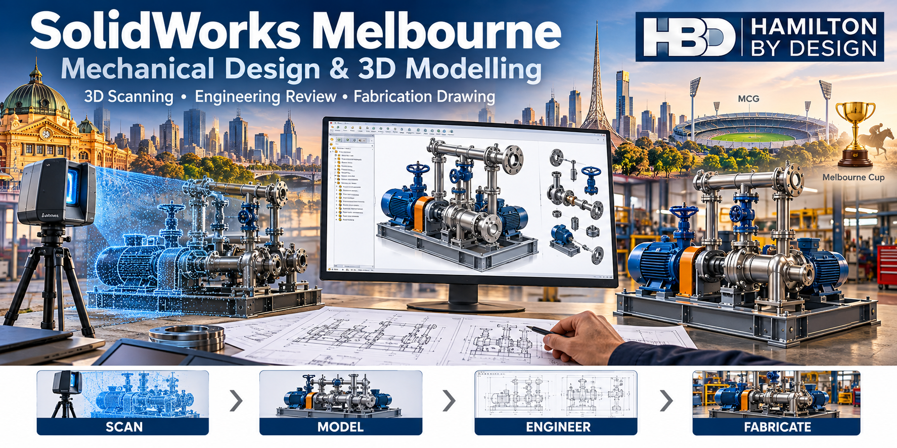
SolidWorks Melbourne

SolidWorks Melbourne illustration showing pump skid scanning, CAD modelling and fabrication, with Melbourne landmarks, the MCG, Melbourne Cup imagery and HBD logo.

SolidWorks Melbourne | Mechanical Engineering & CAD Modelling

Mechanical Engineering & SolidWorks Modelling for Industrial Projects

Hamilton By Design provides SolidWorks services in Melbourne as part of our mechanical engineering consultancy, delivering engineering-led 3D CAD models, drawings, and fabrication-ready documentation for industrial, manufacturing, infrastructure, and construction projects across Victoria.

We donโ€™t offer standalone drafting.
We deliver SolidWorks outcomes that are accurate, buildable, and defensible.


Engineering-Led SolidWorks Services in Melbourne

SolidWorks is a powerful CAD platform โ€” but without proper engineering oversight, models quickly become a liability rather than an asset.

At Hamilton By Design, SolidWorks is used to support:

  • Mechanical engineering design
  • Manufacturing and fabrication outcomes
  • Brownfield upgrades and plant modifications
  • Reverse engineering and asset life-extension

Every model and drawing is developed with real site conditions, manufacturing constraints, and Australian Standards in mind.


Our SolidWorks Capabilities

We provide SolidWorks services in Melbourne for:

๐Ÿ”น Mechanical Design & Modelling

  • Mechanical equipment design and upgrades
  • Structural and mechanical assemblies
  • Load-path-aware modelling
  • Design for fabrication, transport, and installation

๐Ÿ”น 3D CAD Modelling & As-Built Drawings

  • SolidWorks models generated from site data
  • As-built documentation for existing assets
  • Conversion of legacy or incomplete drawings
  • Digital twin models for industrial facilities

๐Ÿ”น Fabrication & Workshop Drawings

  • Fabrication-ready workshop drawings
  • Welded steel structures, platforms, and frames
  • Machined components and assemblies
  • Clear tolerances, weld details, and build intent

๐Ÿ”น Reverse Engineering

  • Unsupported or obsolete OEM components
  • Worn, damaged, or modified equipment
  • Like-for-like replacement or engineered improvement
  • Scan-to-SolidWorks workflows

SolidWorks Supported by LiDAR Scanning

Where accuracy and fit-up are critical, our SolidWorks services are supported by engineering-grade LiDAR scanning.

This allows us to:

  • Capture complex and congested industrial environments
  • Accurately model existing plant and infrastructure
  • Reduce clashes, rework, and installation risk
  • Support shutdown-critical upgrades and tie-ins

This approach is particularly valuable for Melbourne-based manufacturing plants, processing facilities, ports, and infrastructure assets.


Industries We Support in Melbourne & Victoria

Our SolidWorks services are commonly used across:

  • Manufacturing and industrial facilities
  • Infrastructure and utilities
  • Steel fabrication workshops
  • Construction and EPCM projects
  • Ports, logistics, and transport assets

From Melbourne metro to regional Victoria, we deliver consistent, engineering-led outcomes.


Why Choose Hamilton By Design for SolidWorks in Melbourne

  • Mechanical engineers using SolidWorks โ€” not drafting-only providers
  • Models developed for manufacture and construction, not just visualisation
  • Integration with LiDAR scanning and real site data
  • Clear assumptions and engineering accountability
  • Proven experience in manufacturing-heavy environments

We design how manufacturers and fabricators think โ€” and how engineers take responsibility.


Our clients:


SolidWorks Is the Tool โ€” Engineering Is the Service

If youโ€™re searching for SolidWorks Melbourne, what you likely need is:

  • Confidence the model reflects site reality
  • Drawings that can be fabricated and installed without rework
  • Engineering judgement behind every CAD decision

Thatโ€™s exactly what Hamilton By Design delivers.


Hamilton By Design logo displayed on a blue tilted rectangle with a grey gradient background
3D LiDAR scanning and 3D modelling service button โ€” laser scanner capturing a point cloud for engineering and CAD modelling
Mechanical engineering services

Talk to a SolidWorks Engineer in Melbourne

If you need SolidWorks modelling, mechanical design, or fabrication drawings in Melbourne, backed by real engineering experience, weโ€™re ready to help.

Speak with an engineer or request a quote today.

Name
Would you like us to arrange a phone consultation for you?
Address

What Is the Difference Between a Terrestrial Scanner and a LiDAR Scanner?

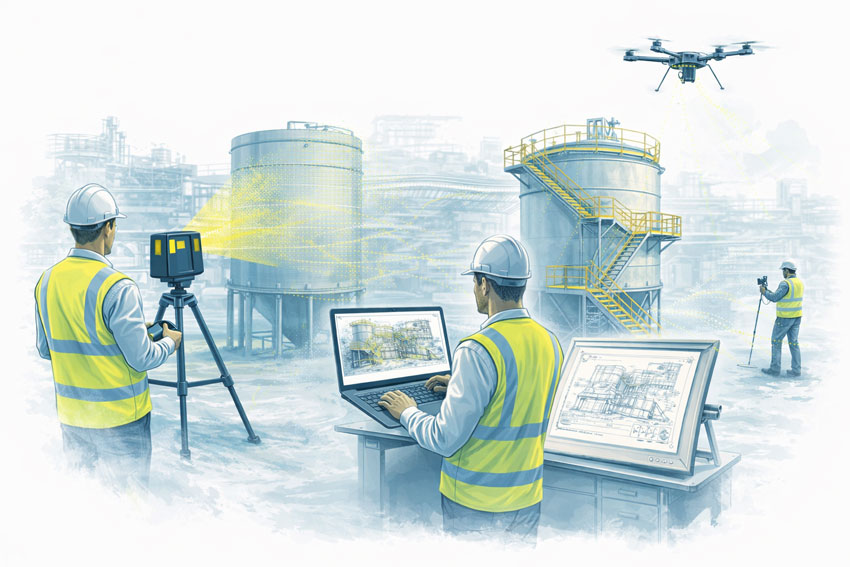
Terrestrial, mobile SLAM and drone LiDAR scanners capturing an industrial plant with engineers reviewing point cloud data and drawings

Terrestrial vs LiDAR Scanners | Whatโ€™s the Difference?

Confusion around terrestrial scanning and LiDAR scanning is common โ€” and understandable.
The two terms are often used interchangeably, even though they describe different things.

This page explains the difference in plain language, shows where each approach fits, and helps you decide what level of accuracy and risk is appropriate for your project.


Short Answer (If Youโ€™re in a Hurry)

LiDAR describes the laser measurement technology.
Terrestrial describes how and where that LiDAR scanner is deployed.

Most terrestrial scanners use LiDAR, but not all LiDAR scanners are terrestrial.


Illustration comparing terrestrial LiDAR, mobile SLAM LiDAR and drone scanning on an industrial facility

What Is LiDAR?

LiDAR (Light Detection and Ranging) is a method of measuring distance using laser light.

How LiDAR works

  • A laser pulse is emitted
  • The pulse reflects off an object
  • The return time is measured
  • Distance is calculated and stored as a 3D point

Millions of these points form a point cloud that represents real-world geometry.

What LiDAR is good for

  • Accurate 3D measurement
  • Complex geometry
  • Low-light or enclosed environments
  • Engineering, construction, and industrial sites

LiDAR answers: How is distance measured?


What Is a Terrestrial Scanner?

A terrestrial scanner is a ground-based scanning system, usually mounted on a tripod or fixed position.

Key characteristics

  • Fixed scan position
  • Controlled setup and coverage
  • Known geometry and reference
  • High repeatability and validation

Typical environments

  • Processing plants and CHPPs
  • Structural steelwork
  • Conveyor systems
  • Brownfield tie-ins
  • As-built verification
  • Shutdown-critical fit-up work

Terrestrial answers: Where and how is the LiDAR deployed?


How the Two Terms Relate (This Is the Important Part)

A terrestrial scanner is a platform.
A LiDAR scanner is a technology.

Most modern terrestrial scanners are terrestrial LiDAR scanners.

Example: a tripod-mounted system such as the FARO Focus S-Series is:

  • LiDAR-based (laser measurement)
  • Terrestrial (ground-based, fixed setup)

Other Common LiDAR Scanner Types (And Why It Matters)

Scanner TypeHow Itโ€™s UsedTypical Outcome
Terrestrial LiDARTripod / fixedHighest control & accuracy
Mobile / SLAM LiDARHandheld / walk-throughFast capture, lower control
Vehicle-mounted LiDARCar / trolleyCorridor mapping
Aerial LiDARDrone / aircraftLarge areas, low detail

All are โ€œLiDARโ€, but not all are suitable for engineering design or fabrication.


Why This Distinction Matters for Projects

Many issues occur when:

  • A LiDAR scan is assumed to be engineering-grade
  • A mobile or SLAM scan is used beyond its intent
  • Accuracy, validation, or limitations are not clearly understood

This doesnโ€™t mean one method is wrong โ€” it means each has a purpose.

The key is aligning the scanner type with:

  • Required accuracy
  • Risk tolerance
  • Fit-up criticality
  • Intended use of the data

Our clients:


Simple Decision Guide (Client in Control)

If you need:

  • Fabrication or replacement parts โ†’ Terrestrial LiDAR
  • Shutdown-critical fit-up โ†’ Terrestrial LiDAR
  • Structural verification โ†’ Terrestrial LiDAR
  • Rapid site context only โ†’ Mobile / SLAM LiDAR
  • Large terrain or stockpiles โ†’ Aerial LiDAR

There is no โ€œone best scannerโ€ โ€” only the right scanner for the outcome you want.


Comparison at a Glance

RequirementTerrestrial LiDARMobile / SLAM LiDAR
Accuracy controlHighModerate
RepeatabilityHighLower
Engineering defensibilityStrongLimited
Fit-up confidenceSuitableNot recommended
Capture speedSlowerFaster
Best use caseDesign & fabricationVisualisation & context

A Note on Engineering Use

Where scanning data feeds into engineering design, documentation, or fabrication, higher-control methods are typically required to align with engineering practice and Australian Standards expectations.

That doesnโ€™t remove choice โ€” it simply means the assumptions and limitations must match the intended use.


How We Approach This (Without Locking You In)

Weโ€™re happy to:

  • Work with terrestrial, mobile, or supplied scan data
  • Validate data before design where required
  • Align scanning effort with your risk, budget, and outcome
  • Clearly document assumptions and limitations

You stay in control of the approach โ€” our role is to make sure the data supports the outcome you expect.


Hamilton By Design logo displayed on a blue tilted rectangle with a grey gradient background
3D LiDAR scanning and 3D modelling service button โ€” laser scanner capturing a point cloud for engineering and CAD modelling
Mechanical engineering services

Next Step

If youโ€™re unsure which scanning method suits your project:

Fill out the contact form and tell us:

  • What you want to build, replace, or verify
  • How the data will be used
  • Any constraints (budget, time, shutdown windows)

Weโ€™ll help you select a fit-for-purpose scanning approach, not just a scanner.


Name
Would you like us to arrange a phone consultation for you?
Address
Finite Element Analysis (FEA) engineering simulation button
Mechanical engineering services

Reverse Engineering 3D Scanning Sydney

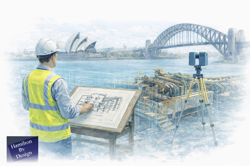
Engineer-led reverse engineering with 3D scanning and drafting overlooking Sydney Harbour and the Harbour Bridge

One Accountable Engineer from Scan to Fabrication โ€” Supporting NSW & Remote Sites

At Hamilton By Design, we provide reverse engineering supported by engineering-grade 3D LiDAR scanning from our Sydney engineering hub, helping maintenance teams, project engineers, and manufacturers replace, reproduce, or validate critical components when drawings are missing, obsolete, or no longer reflect reality.

We specialise in like-for-like replacement and fit-for-purpose engineering, particularly for CHPP plants, conveyors, and brownfield industrial assets, where shutdown time is limited and poor fit-up is not an option.


Mechanical engineer reverse engineering industrial equipment using 3D LiDAR scanning beside Sydney Harbour

Reverse Engineering Built on Real Site Data

Reverse engineering only works when it is based on accurate, defensible data.

We use engineering-grade LiDAR 3D scanning as the foundation for reverse engineeringโ€”capturing real geometry from worn, modified, or undocumented assets and converting that data into engineered models and drawings suitable for fabrication and installation.

This removes reliance on:

  • Missing or outdated drawings
  • OEM data that no longer reflects site reality
  • Assumptions made during manual measurement
  • โ€œBest guessโ€ modelling during shutdowns

Managing Director Insight

โ€œReverse engineering isnโ€™t about copying what you see โ€” itโ€™s about understanding how an asset actually works, how itโ€™s worn, and how it needs to fit during a shutdown. We use 3D scanning to capture reality, but itโ€™s engineering judgement that turns that data into something that can be fabricated and installed with confidence.โ€

โ€” Anthony Hamilton, Managing Director, Hamilton By Design


What We Reverse Engineer

From our Sydney engineering base, we support NSW and remote operations with reverse engineering of:

  • Conveyor components (pulleys, frames, guards, transfer assemblies)
  • CHPP plant equipment (chutes, hoppers, screens, wear liners)
  • Worn or damaged components requiring like-for-like replacement
  • Obsolete or unsupported OEM parts
  • Structural steel components and assemblies
  • Machined components and housings

These are typically assets that cannot be easily re-measured, are already worn or distorted, or must be replaced accurately within tight shutdown windows.


Engineering-Grade Accuracy for Shutdown-Critical Fit-Up

Our reverse engineering approach is designed for shutdown-critical fit-up, not visual modelling.

We emphasise:

  • Engineering-grade LiDAR suitable for fit-for-purpose replacement parts
  • Accuracy verified through engineering judgement, not just point clouds
  • Manual verification of critical interfaces where required
  • Deliverables suitable for fabrication and installation

Our work is engineering-grade and defensibleโ€”not survey-grade, but appropriate for mechanical and structural replacement in operating plant environments.


Reverse Engineering as an Engineering Process

We treat reverse engineering as a full engineering process, with 3D scanning as one inputโ€”not the answer by itself.

Our typical workflow includes:

3D LiDAR scanning โ†’ point-cloud review โ†’ engineered 3D modelling โ†’ design intent definition โ†’ drawings and fabrication documentation

Where required, this process may also include:

  • Mechanical or structural checks
  • Fit-for-purpose assessment
  • Review of wear patterns and failure modes

This ensures replacement components are designed to work, not simply copied.


Engineering Ownership, Accountability & Risk Management

Reverse engineering carries real risk, particularly during shutdowns.

Our approach includes:

  • Engineering sign-off and accountability
  • Clear documentation of assumptions and limitations
  • Fit-for-purpose design intent (not blind replication)
  • Engineering judgement aligned with Australian Standards
  • Lessons learned from real shutdowns and replacement projects

Our documentation is suitable for internal reviews, audits, and compliance checks.


Our clients:


Sydney Engineering Hub Supporting NSW & Remote Sites

We operate with Sydney as our engineering base, supporting:

  • NSW industrial and mining operations
  • CHPP plants and bulk materials facilities
  • Remote sites supported from NSW
  • Fabricators and manufacturers requiring accurate reverse-engineered data

This model combines local engineering accountability with support for geographically dispersed assets.


Designed for Maintenance, Reliability & Project Engineers

This service is ideal for:

  • Maintenance and reliability engineers managing ageing assets
  • Project engineers planning shutdown replacements
  • Manufacturers reproducing legacy components
  • Asset owners dealing with undocumented modifications
  • CHPP operators requiring like-for-like replacement

We work collaboratively with your teams and fabricators, focusing on getting it right the first time.


Hamilton By Design logo displayed on a blue tilted rectangle with a grey gradient background
3D LiDAR scanning and 3D modelling service button โ€” laser scanner capturing a point cloud for engineering and CAD modelling
Mechanical engineering services

Talk to Us About Reverse Engineering 3D Scanning in Sydney

If youโ€™re dealing with missing drawings, obsolete parts, or shutdown-critical replacements, weโ€™d welcome the opportunity to help.

Submit an enquiry via our contact form

Name
Would you like us to arrange a phone consultation for you?
Address
3D Scanning Sydney banner promoting engineering-grade 3D laser scanning, LiDAR scanning, and reality capture services by Hamilton By Design.
Mechanical Engineering Sydney banner with white text on a blue background representing Hamilton By Design's mechanical engineering services in Sydney.
Mechanical Drafting and 3D Modelling Sydney banner highlighting Hamilton By Design's CAD drafting, 3D modelling, and engineering design services in Sydney.

Hamilton By Design provides engineering-led 3D scanning, LiDAR scanning, mechanical engineering and digital engineering services throughout Sydney and Greater Sydney.

Explore our related Sydney services:


  • 3D Scanning Sydney โ€“ Engineering-grade terrestrial laser scanning, as-built surveys and point cloud capture for industrial, infrastructure and commercial projects.
  • Reality Capture Sydney โ€“ High-accuracy reality capture, digital twins, asset documentation and engineering-grade site verification.
  • Scan to CAD Sydney โ€“ Convert point cloud data into AutoCAD, SolidWorks, Inventor and other engineering-ready CAD deliverables.
  • Point Cloud Modelling Sydney โ€“ Engineering-grade point cloud processing, clash detection, as-built verification and 3D modelling.
  • Mechanical Engineering Sydney โ€“ Mechanical design, plant upgrades, materials handling systems, conveyors, chutes, platforms and engineering support.
  • Structural Drafting Sydney โ€“ Structural steel drafting, fabrication drawings, GA drawings, workshop detailing and as-built documentation.

Hamilton By Design supports projects throughout Sydney CBD, Parramatta, Liverpool, Penrith, Blacktown, Chatswood, Alexandria, Mascot, Newcastle and the Central Coast.


Mechanical Engineering | Structural Engineering


Blue banner graphic displaying the text "Point Cloud to CAD - Australia" in large white lettering, representing point cloud processing, scan-to-CAD conversion and digital engineering services across Australia.
Blue banner graphic displaying the text "Scan to CAD Sydney" in large white lettering, representing engineering-led point cloud to CAD conversion, LiDAR scanning and digital engineering services in Sydney.
Blue banner graphic displaying the text "Reality Capture Sydney - CBD" in large white lettering, representing engineering-led reality capture, LiDAR scanning and digital engineering services within Sydney CBD commercial buildings and infrastructure.