3D Scanning for Central West NSW Gold and Copper Processing Plants

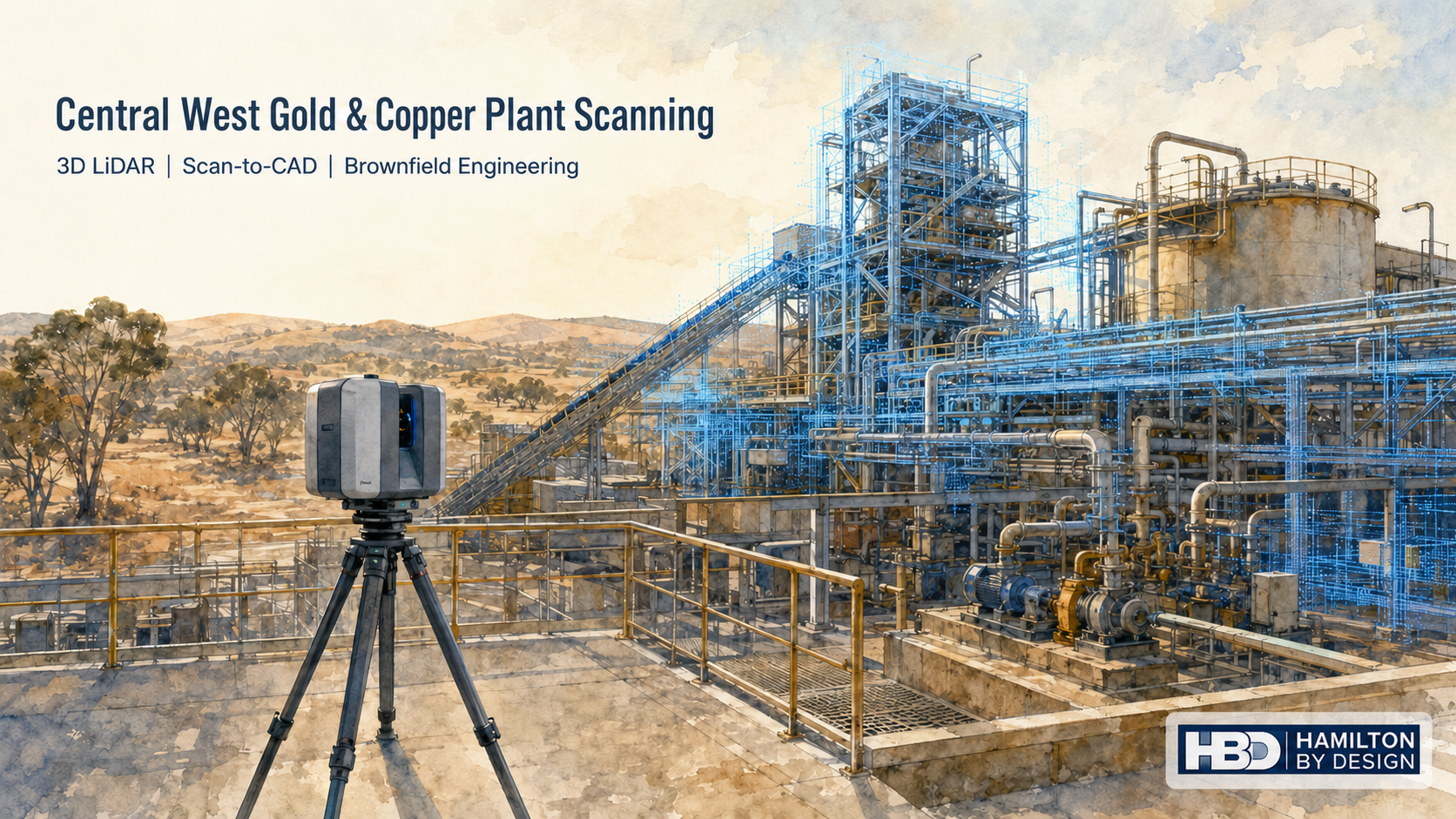
Watercolour illustration of 3D LiDAR scanning at a Central West NSW gold and copper processing plant, showing pipework, conveyors, structural steel and the Hamilton By Design logo.

Gold and copper processing plants are difficult places to measure accurately. They often include dense pipework, conveyors, chutes, tanks, platforms, pumps, valves, handrails, cable trays and structural steel, all working together in a tight operating environment. Over time, these plants are modified during shutdowns, maintenance works and production upgrades. The result is that the real plant may no longer match the original drawings.

For engineers, maintenance planners and project teams, this creates a major problem. If the existing site information is incomplete or wrong, design decisions are made on assumptions. That can lead to clashes, poor access, rework, fabrication errors and costly delays during shutdowns.

Hamilton By Design provides engineering-grade 3D LiDAR scanning for gold and copper processing facilities across Orange, Blayney, Bathurst, Parkes and the wider Central West NSW region. Our scanning workflow helps capture accurate plant, pipework and structural data so engineers can plan upgrades, modifications and shutdown works with greater confidence.

For local engineering support in the region, Hamilton By Design also provides 3D Scanning Engineering in Orange for industrial, mining, infrastructure and processing plant projects.

Why Gold and Copper Processing Plants Are Hard to Measure

Gold and copper processing infrastructure is rarely simple. A typical plant area may include crushing, grinding, flotation, concentrate handling, dewatering, pumping systems, pipe racks, access platforms and structural supports. These systems are often layered around one another and squeezed into existing plant envelopes.

Manual measurement can be slow and difficult in these environments. It may require repeated access to elevated areas, congested walkways, shutdown zones or restricted plant areas. Even with careful site work, it is easy to miss critical details such as flange positions, pipe offsets, structural interferences, access clearances, equipment footprints or support steel locations.

The issue becomes more serious when fabrication is involved. A pipe spool, chute liner, access platform or replacement support frame may look correct on a drawing, but if the existing plant has moved, been modified or was never built exactly as drawn, the new item may not fit.

3D LiDAR scanning helps reduce this risk by capturing the real site condition before design and fabrication decisions are made.

What 3D LiDAR Scanning Captures

A 3D LiDAR scanner captures millions of measurement points from the visible plant environment. These points form a digital point cloud that can be used to measure, model and verify existing site conditions.

In a Central West gold or copper processing plant, 3D scanning can be used to capture:

  • Pipework and pipe racks
  • Pumps, motors and drive arrangements
  • Tanks, vessels and hoppers
  • Conveyors and transfer points
  • Chutes, guards and skirt systems
  • Platforms, stairs, ladders and handrails
  • Structural steel frames and supports
  • Floor levels, slab edges and equipment bases
  • Existing equipment footprints
  • Access restrictions and maintenance zones
  • Building envelopes and surrounding infrastructure

This information can then be used by engineers, drafters, fabricators and maintenance teams to make better decisions before work reaches site.

Hamilton By Designโ€™s broader Engineering-Grade LiDAR Scanning service is focused on capturing scan data that can be used for real engineering decisions, not just visual reference.

Supporting Orange and Central West NSW Processing Projects

Orange and the Central West NSW region support major mining, processing, agricultural, industrial and infrastructure activity. For gold and copper processing plants in this region, accurate site information is especially important because many projects are brownfield upgrades rather than new greenfield construction.

Brownfield projects are difficult because the design has to fit around what already exists. Existing plant may have been modified over many years. Old drawings may be missing, incomplete or no longer correct. Access may be limited. The new work may need to be installed during a short shutdown window.

Hamilton By Design can support Central West NSW projects involving:

  • Processing plant upgrades
  • Conveyor and chute modifications
  • Pipework replacement
  • Pump and tank modifications
  • Structural platform upgrades
  • Access and maintenance improvements
  • Scan-to-CAD modelling
  • Shutdown planning
  • Fabrication drawing preparation
  • Clash checking and design verification

The aim is to capture the site once, process the information properly and give the project team data they can actually use.

Turning Site Reality into Engineering Data

The value of 3D scanning is not only in the scan itself. The real value comes from turning the scan into useful engineering information.

A point cloud can be used to check clearances, measure distances, create sections, confirm equipment positions and model existing infrastructure. From there, the data can support CAD modelling, general arrangement drawings, fabrication design and installation planning.

For example, if a processing plant needs a pipework modification, the scan can help confirm the existing pipe route, flange orientation, valve access, nearby structural steel and installation clearances. If a chute or transfer point needs work, the scan can help confirm belt position, head pulley geometry, surrounding access platforms and support steel. If a platform needs upgrading, the point cloud can help verify levels, columns, handrails and connection points.

For projects where existing conditions are uncertain, Hamilton By Designโ€™s 3D LiDAR Scanning for As-Built & Brownfield Engineering provides a practical workflow for capturing the real site before design decisions are locked in.

How the Scanning Process Works

A typical Central West plant scanning project starts with a short discussion about the problem being solved. Some clients need a registered point cloud only. Others need CAD modelling, drawings, sections, elevations or fabrication support.

The usual workflow includes:

  1. Review the plant area and project objective
  2. Plan scanner locations and site access requirements
  3. Complete LiDAR scanning of the required area
  4. Register the scan data into a single point cloud
  5. Review scan coverage and data quality
  6. Export point cloud files such as E57, RCP or RCS
  7. Complete scan-to-CAD modelling if required
  8. Prepare drawings, sections or engineering deliverables if required

This process gives the project team a reliable record of existing conditions. It also reduces the need for repeated site visits, which can be important when access is limited or the plant is operating.

Tools Used to Assist the Work

Hamilton By Design uses scanning, modelling and drafting tools suited to mechanical and structural plant work. Depending on the project, the workflow may include FARO LiDAR scanning, FARO SCENE, Autodesk ReCap, Navisworks, SolidWorks, Inventor and AutoCAD.

Common deliverables may include:

  • Registered point clouds
  • E57, RCP, RCS or LAS files
  • 3D CAD models
  • General arrangement drawings
  • Sections and elevations
  • Pipework layouts
  • Equipment set-out drawings
  • Fabrication drawings
  • Clash review models
  • As-built documentation

The purpose is to make the scan useful for engineering, fabrication and installation. A point cloud may be valuable on its own, but many clients need the next step: clear CAD geometry, practical drawings and engineering interpretation.

Hamilton By Design also provides 3D LiDAR Scanning & Digital QA Verification for projects where existing or fabricated components need to be checked against design requirements.

Reducing Shutdown and Fabrication Risk

Shutdown work is expensive because the available window is usually short. Labour, cranes, scaffolding, access equipment, fabrication, transport and production downtime all need to line up. If a fabricated item does not fit, the cost is rarely limited to the part itself. The real cost is the delay, rework and disruption around it.

3D scanning can help reduce this risk before shutdown work begins. It allows the project team to check the existing plant condition early and ask practical questions such as:

  • Does the proposed pipe route fit?
  • Are the existing drawings still reliable?
  • Is there enough access for installation?
  • Will the new chute clear the existing structure?
  • Are there clashes with handrails, cable trays or supports?
  • Can the replacement item be modelled before removal?
  • What needs to be verified before fabrication starts?

For processing plants, this is where scan data becomes a risk-reduction tool. It helps move uncertainty from site into the design stage, where problems are cheaper and easier to solve.

Why Use an Engineering-Led Scanning Provider?

Not all scanning services are the same. A scanner can capture geometry, but engineering judgement helps determine what needs to be captured, how the information will be used and which details matter.

Hamilton By Design combines 3D LiDAR scanning with mechanical engineering, CAD modelling and drafting experience. This means the scan is planned around the final outcome, whether that is a point cloud, a CAD model, a pipework layout, a platform drawing, a chute design or a shutdown planning model.

For gold and copper processing facilities, this is important because the site is not just a shape to be recorded. It is an operating plant with mechanical systems, access constraints, maintenance requirements and fabrication realities.

Engineering-led scanning helps ensure the right areas are captured, the correct interfaces are considered and the final deliverables support real project decisions.

FAQs

What is 3D scanning used for in a gold or copper processing plant?

3D scanning is used to capture accurate existing conditions of plant, pipework, conveyors, chutes, tanks, platforms, structural steel and access systems. The scan data can then support engineering design, shutdown planning, fabrication, clash checking and as-built documentation.

Why is 3D scanning better than manual measurement?

Manual measurement can be slow, incomplete and difficult in congested plant areas. 3D scanning captures millions of points across the visible environment, giving engineers a more complete digital record of the site. It also reduces the need for repeated site visits.

Can 3D scanning help with shutdown planning?

Yes. Scanning can help project teams verify existing conditions before a shutdown begins. This can reduce the risk of fabricated parts not fitting, clashes with existing plant, access problems and unexpected site issues.

What areas of a processing plant can be scanned?

Typical areas include pipe racks, pump bays, conveyors, transfer stations, chutes, tanks, platforms, stairs, handrails, structural steel, equipment bases and surrounding access areas.

What file formats can be supplied?

Depending on the project, point cloud data can be supplied in formats such as E57, RCP, RCS or LAS. CAD deliverables may include DWG, DXF, STEP, SAT, Parasolid, SolidWorks or Inventor files.

Can the scan be converted into CAD drawings?

Yes. Scan data can be converted into CAD models, general arrangement drawings, sections, elevations, pipework layouts, fabrication drawings and as-built documentation.

Is this suitable for brownfield plant upgrades?

Yes. Brownfield upgrades are one of the strongest uses for 3D scanning. It helps engineers understand what is already built before designing new work around it.

Does Hamilton By Design service Orange and Central West NSW?

Yes. Hamilton By Design supports engineering, 3D scanning, scan-to-CAD and drafting work across Orange, Blayney, Bathurst, Parkes and the wider Central West NSW region.

Central West Gold and Copper Plant Scanning

For gold and copper processing facilities across Orange and Central West NSW, 3D scanning provides a practical way to capture complex existing infrastructure before engineering work begins. It helps project teams reduce manual measurement, improve design confidence and plan upgrades with better information.

Hamilton By Design can assist with plant scanning, scan-to-CAD modelling, pipework verification, structural drafting, conveyor and chute upgrades, shutdown planning and brownfield engineering support.

If your team is planning work around a Central West NSW processing plant, 3D LiDAR scanning can help turn a complicated site into reliable engineering data before the job reaches fabrication, shutdown or site installation.

Talk to Us – Contact Us

Name
Would you like us to arrange a phone consultation for you?
Address

Our clients:


Orange NSW 3D LiDAR Scanning for Brownfield Processing Plants

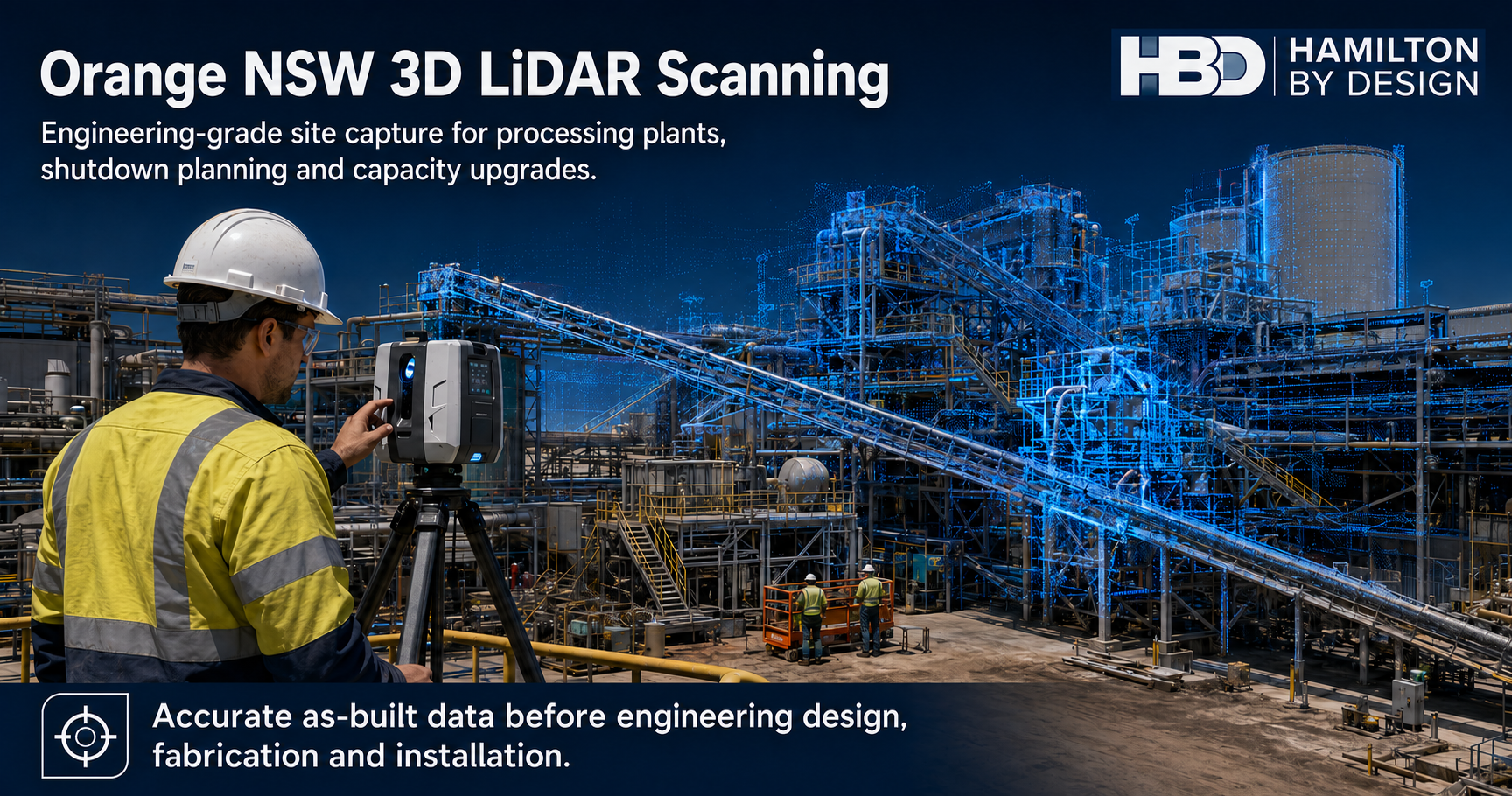
Engineer using a 3D LiDAR scanner at an Orange NSW processing plant with point cloud data overlay for as-built documentation and plant upgrade planning.

Brownfield processing plants around Orange NSW and the Central West mining region often carry years of site changes, shutdown modifications, maintenance repairs and practical site-based upgrades. Over time, the plant that exists on site can become very different from the original drawings.

For engineers, maintenance teams and project managers, this creates a serious problem.

Before a plant upgrade, conveyor modification, chute redesign, structural change or shutdown project can be completed with confidence, the design team needs to know what is actually installed. That is where engineering-grade 3D LiDAR scanning in Orange NSW becomes valuable.

Hamilton By Design provides engineer-led 3D LiDAR scanning for processing plants, mine sites and heavy industrial facilities across Orange NSW and the Central West. The goal is simple: capture accurate as-built site data so engineering design, shutdown planning and capacity upgrade work can be based on real site conditions.

The Problem With Brownfield Processing Plants

Brownfield plants are rarely simple.

Processing plants are changed over many years to keep production running. A platform may be extended. A chute may be modified. A conveyor may be upgraded. Pipework may be rerouted. Guards, access stairs, handrails, tanks, pumps and structural supports may all change as the site grows.

The issue is that the drawings are not always updated after each modification.

This means engineers and contractors can be working from drawings that are incomplete, outdated or missing important site details. For a simple job, this may cause minor delays. For a major shutdown or capacity upgrade, it can create expensive problems.

Common issues include:

  • New equipment does not fit the existing space
  • Pipework clashes with structural steel
  • Platforms or handrails block installation access
  • Existing drawings do not match the plant
  • Tie-in points are not where the design expected
  • Fabricated parts require site rework
  • Shutdown tasks take longer than planned
  • Workers need to spend more time measuring in live plant areas

In a mining or processing environment, these problems affect more than drafting quality. They affect safety, cost, schedule and production.

Who Needs 3D LiDAR Scanning in Orange NSW?

3D LiDAR scanning is useful for any team that needs accurate site information before making engineering decisions.

For mine operators and processing plant owners, LiDAR scanning provides a reliable record of existing conditions before upgrades or shutdowns begin.

For project engineers, it gives a clear basis for design. Instead of relying only on old drawings, they can work from current site data.

For maintenance supervisors, it helps identify access constraints, equipment locations and workfront issues before trades arrive on site.

For mechanical and structural engineers, the point cloud can support design of chutes, hoppers, conveyors, platforms, walkways, pipe supports, guarding and mechanical equipment layouts.

For fitters, riggers and boilermakers, the benefit is practical. Better site data means fewer surprises during installation.

For drafting teams, the scan can be used to develop CAD models, sections, elevations and fabrication drawings.

In short, 3D scanning helps connect the real plant with the engineering design process.

What Is 3D LiDAR Scanning?

3D LiDAR scanning is a method of capturing real-world site geometry using laser measurement. A terrestrial scanner is set up in multiple positions around the plant. Each scan captures millions of measured points from visible surfaces.

These points are then registered together to create a point cloud.

A point cloud is a digital 3D record of the existing site. It can show structures, conveyors, stairs, tanks, pipework, platforms, equipment, building columns and surrounding access areas.

For engineering work, the point cloud can then be used to create:

  • 3D CAD models
  • 2D layout drawings
  • Sections and elevations
  • As-built documentation
  • Clash checks
  • Equipment layout studies
  • Fabrication references
  • Shutdown planning information

The key benefit is that the design team can see and measure the real plant without relying only on historical drawings.

Where This Applies Around Orange NSW

Orange NSW is part of the broader Central West / Orange mining and industrial region. The area includes mining operations, processing infrastructure, workshops, materials handling systems and heavy industrial facilities.

3D LiDAR scanning is especially useful in:

  • Processing plants
  • Concentrator areas
  • Conveyor systems
  • Transfer stations
  • Crusher and screening areas
  • Pump and pipework areas
  • Tank farms
  • Workshops
  • Structural platforms
  • Access stairs and walkways
  • Shutdown workfronts
  • Brownfield upgrade areas

The service is not limited to one type of equipment. It is most valuable anywhere the existing plant layout is complex and accurate information is needed before engineering design begins.

How The Scanning Process Works

A typical 3D LiDAR scanning workflow starts with understanding the problem.

The first step is to identify what the client needs to achieve. For example, the project may involve increasing plant capacity, replacing a chute, modifying a conveyor, installing new pipework, upgrading access platforms or checking if new equipment will fit.

Once the work area is understood, the site is scanned from multiple locations. The scanner captures visible geometry from each position. In complex plant areas, multiple scan positions are usually required so the final point cloud has enough coverage around equipment, platforms, pipework and structural steel.

After site capture, the scan data is registered. This means the individual scans are aligned into one coordinated point cloud.

From there, the data can be reviewed and used for engineering work. Depending on the project, Hamilton By Design can provide point cloud files, CAD models, mechanical layouts, structural drafting support, sections, elevations or scan-to-CAD deliverables.

The output depends on the problem being solved.

For some projects, the client may only need point cloud data to support their own design team. For others, they may need a full engineering workflow from scanning through to CAD modelling and drawing production.

Tools That Assist In Solving The Problem

The value of 3D LiDAR scanning comes from both the site capture and the engineering interpretation after the scan.

Common tools used in this workflow include:

ToolPurpose
FARO Focus ScannerCaptures accurate terrestrial LiDAR scan data on site
FARO SCENERegisters and processes scan data into a point cloud
Autodesk ReCapConverts and manages point cloud files for CAD workflows
NavisworksSupports model review, coordination and clash checking
SolidWorksMechanical design, modelling and equipment layout development
InventorMechanical modelling and fabrication design workflows
AutoCAD2D layouts, sections, elevations and drafting deliverables
Point Cloud DataProvides the accurate as-built reference for design decisions

The scanner captures the plant. The software helps organise the data. The engineering process turns that data into decisions.

This is where engineer-led scanning becomes important. A scan is not just a visual record. It needs to be captured and processed in a way that supports the design outcome.

Supporting Capacity Upgrade Projects

One of the strongest reasons to use 3D LiDAR scanning is to support plant upgrades aimed at increasing capacity.

When a site wants to increase throughput, the upgrade may involve larger equipment, modified chutes, conveyor changes, new pipe routes, additional pumps, upgraded platforms or changes to access and maintenance areas.

In a brownfield plant, the available space is usually constrained.

A capacity upgrade can fail or become expensive if the new design does not properly account for what is already installed. A larger chute may clash with a platform. A conveyor upgrade may affect guarding or access. New pipework may run into structural steel. A maintenance access route may be blocked by new equipment.

3D LiDAR scanning helps reduce this risk by confirming the actual site geometry before design and fabrication.

This allows engineers to test the design against the real plant. It also helps contractors understand installation constraints before the shutdown begins.

For capacity upgrade work, LiDAR scanning can help answer questions such as:

  • Will the new equipment fit?
  • Are there clashes with existing steel or pipework?
  • Can the equipment be installed safely?
  • Is there enough access for maintenance?
  • What needs to be removed or modified before installation?
  • Can fabrication be completed with more confidence?
  • Are there structural or access issues that need to be addressed early?

By answering these questions before the shutdown, the company can reduce the risk of delays and rework.

The Upside For Workers

For workers, better site data means clearer planning and fewer surprises.

Fitters, riggers, boilermakers and maintenance crews are often the people who discover design problems during installation. If something does not fit, they are left to solve the issue under time pressure, often during a shutdown.

That is not ideal.

Accurate 3D scanning helps move those problems earlier in the process, where they can be dealt with during design rather than during installation.

The upside for workers includes:

  • Less time spent measuring complex areas by hand
  • Better understanding of access constraints
  • Clearer shutdown work packs
  • Reduced rework during installation
  • Better lift and access planning
  • Fewer unexpected clashes
  • Improved communication between engineers and trades
  • Less time spent in operating plant areas gathering measurements

Good site information also supports safer conversations during planning. Workers can see the work area, understand the constraints and identify issues before the job starts.

The Upside For The Company

For the company, the value is measured in reduced risk.

A processing plant shutdown can be expensive. If a design is wrong, or if fabricated parts do not fit, the cost can grow quickly. Delays can affect production, labour costs, crane time, contractor coordination and commissioning.

3D LiDAR scanning helps reduce these risks by improving the quality of information at the start of the project.

The upside for the company includes:

  • Better engineering decisions
  • Reduced design uncertainty
  • Fewer site clashes
  • Less fabrication rework
  • More reliable shutdown planning
  • Improved contractor coordination
  • Better as-built documentation
  • Faster concept development
  • Stronger governance around design changes
  • Better support for future upgrades

The point cloud can also become a useful record for future work. Once captured, it can be reused for planning, design reviews and later modifications.

Why Engineering-Grade Scanning Matters

Not all scanning is the same.

For mining and heavy industry, the scan needs to support engineering decisions. That means the capture process must consider accuracy, coverage, file formats, access constraints, site safety and the final deliverable required by the project.

A basic visual scan may look impressive, but it may not provide the right information for design.

Engineering-grade scanning focuses on practical outputs. The goal is not just to create a digital image of the plant. The goal is to support real engineering work.

That may include modelling a chute, checking conveyor clearances, developing a platform layout, producing fabrication drawings or verifying a shutdown workfront.

Hamilton By Design combines 3D LiDAR scanning with mechanical engineering and CAD capability. This means the scan can be connected directly to the design process.

Example Use Cases

A processing plant in Orange NSW may use 3D LiDAR scanning before replacing a transfer chute. The scan can capture the conveyor, structure, access platforms, surrounding steel and installation constraints. This helps the chute design fit the real plant and reduces the chance of site modifications during installation.

A shutdown team may use scanning to prepare work packs before a major outage. The point cloud can help confirm access, equipment positions and nearby clashes.

A project engineer may use scanning before a capacity upgrade. The scan can help test whether larger equipment or modified conveyors will fit within the existing plant.

A structural engineer may use the point cloud to check platform layouts, stairs, handrails and support locations before producing design documentation.

A drafting team may use scan-to-CAD workflows to create updated layouts where existing drawings are missing or unreliable.

Hamilton By Design logo displayed on a blue tilted rectangle with a grey gradient background

For brownfield processing plants in Orange NSW and the Central West, accurate as-built information is one of the most important inputs into good engineering design.

Old drawings, incomplete records and years of site modifications can create risk before a project even starts. 3D LiDAR scanning helps solve that problem by capturing the real plant and turning it into usable engineering data.

For workers, this means clearer planning, fewer surprises and better shutdown preparation.

For companies, it means reduced rework, better design confidence, stronger project governance and improved support for capacity upgrades.

Hamilton By Design provides engineering-grade 3D LiDAR scanning in Orange NSW for processing plants, shutdown planning, structural upgrades and accurate as-built documentation. The result is better information before design, fabrication and installation begin.


Talk to Us – Contact Us

Name
Would you like us to arrange a phone consultation for you?
Address

Our clients:


Shiploader 3D Scanning Perth

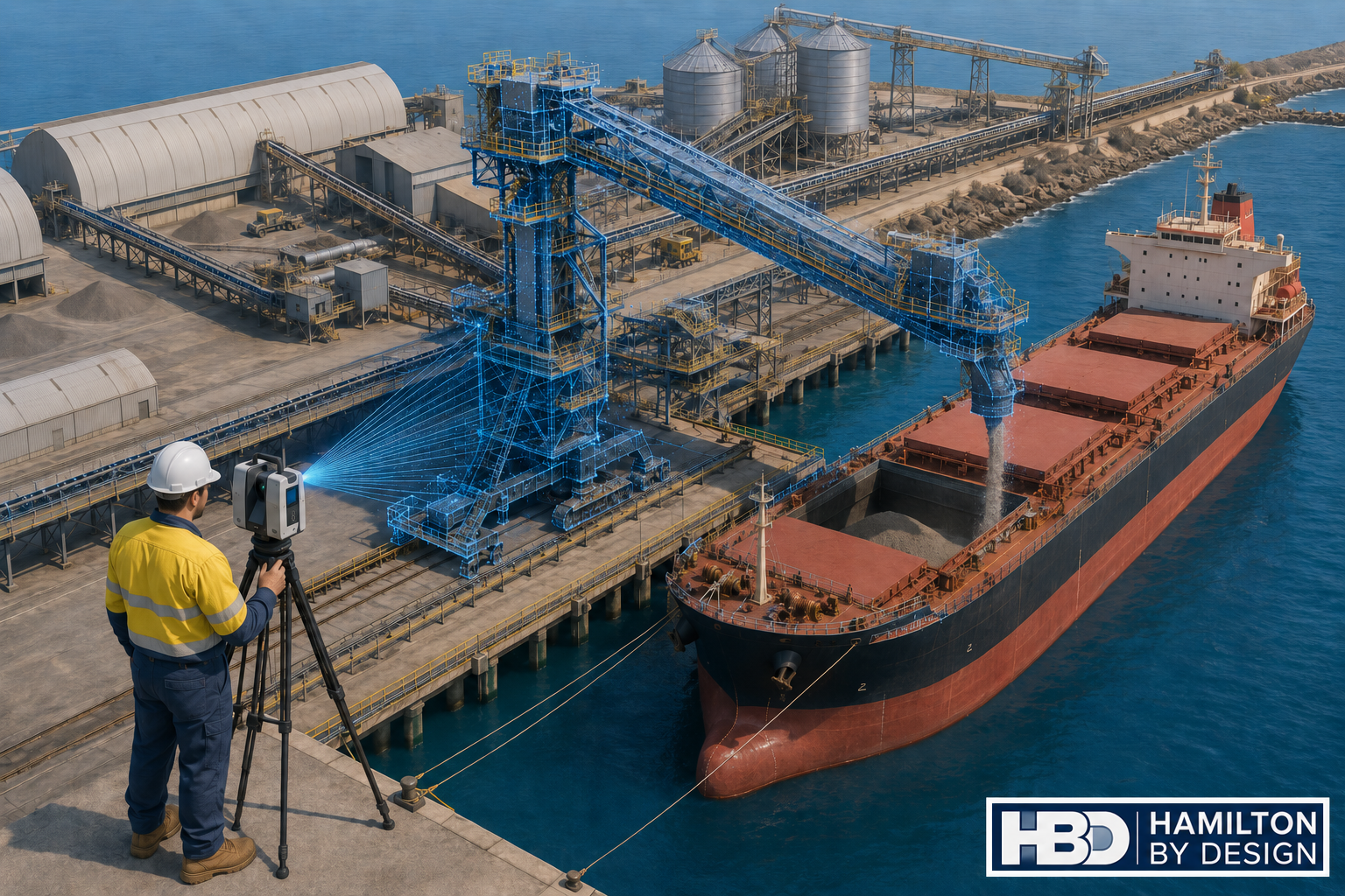
Engineer using a LiDAR scanner to capture a shiploader, conveyor system and bulk carrier at a Perth port.

Engineering-Grade LiDAR Scanning for Ports, Bulk Handling and Brownfield Shiploader Upgrades

Hamilton By Design provides shiploader 3D scanning in Perth for port operators, bulk handling facilities, engineers, fabricators and maintenance teams working with ageing shiploaders, conveyors, chutes, booms, wharf structures and access platforms.

Shiploaders are large, complex and difficult assets to modify safely. They operate in harsh marine environments, often handling abrasive bulk materials such as minerals, grain, fertiliser, alumina, coal, ore or other export products. Over time, these machines are repaired, strengthened, modified and upgraded. The problem is that the drawings do not always keep up with the real asset.

That creates risk.

When a port operator needs to replace a chute, modify a conveyor, inspect a boom, upgrade access platforms, install guarding, check clearances or plan a shutdown, the team needs accurate existing-condition data. If the project starts with old drawings or incomplete site measurements, the risk of fabrication errors, installation clashes and shutdown delays increases quickly.

Hamilton By Design uses engineering-grade LiDAR scanning to capture accurate site geometry before design, fabrication or shutdown work begins. The scan data can then be used for point cloud review, Scan-to-CAD modelling, clash checking, general arrangement drawings, fabrication support and as-built documentation.

For broader Western Australian site capture and engineering support, see our 3D Scanning Perth services.

Why Shiploader 3D Scanning Matters

A shiploader is not a simple conveyor. It is a complete mechanical, structural and operational system. A typical shiploader may include boom structures, conveyor galleries, transfer chutes, hoppers, skirts, drives, pulleys, take-up systems, dust control equipment, hydraulic systems, electrical routes, access platforms, walkways, stairs, handrails, guarding, rails, wharf interfaces and surrounding port infrastructure.

Many of these areas are difficult to measure manually. Some areas are elevated. Some are close to operating plant. Some are affected by corrosion, impact damage, product build-up, wear or previous modifications. Manual measurement may be suitable for small items, but it is often not enough when the design team needs to understand how the whole asset fits together.

3D scanning captures millions of measured points across the shiploader and surrounding infrastructure. The result is a digital point cloud that can be measured, reviewed and converted into usable engineering deliverables.

This is especially valuable for brownfield port environments where the installed condition often differs from the original drawings.

The Biggest Problem: Inaccurate As-Built Data

The biggest problem for port operators and engineers is that ageing shiploaders often do not have accurate as-built data.

Original drawings may exist, but they may no longer reflect the current condition of the machine. Over many years, shiploaders are maintained, repaired and modified. Chutes are replaced. Guards are added. Platforms are changed. Steelwork is strengthened. Conveyor components are adjusted. Services are rerouted. Dust control systems are modified. Access systems are upgraded.

Each change may make sense at the time, but unless the drawings are updated properly, the asset slowly drifts away from the documentation.

This creates problems when new work is planned.

An engineer may design a replacement chute based on old drawings, only to find that the surrounding structure has changed. A fabricator may manufacture a component that clashes with existing steelwork. A shutdown team may plan an installation sequence without knowing that access is restricted. A maintenance team may discover during the shutdown that the lifting path is blocked.

For a shiploader, these problems can become expensive quickly. Shutdown windows are limited. Port operations are time-sensitive. Fabrication rework can delay installation. A small measurement error can become a major site issue.

3D scanning helps reduce this risk by capturing the real installed condition before design and fabrication decisions are made.

Who Uses Shiploader 3D Scanning?

Shiploader 3D scanning is useful for several project groups.

Port operators use scan data to understand existing assets, plan maintenance and reduce shutdown risk.

Mechanical engineers use point clouds and CAD models to design chute modifications, conveyor interfaces, guards, brackets, transfer points and replacement components.

Structural engineers use scan data to review steelwork, access platforms, stairs, handrails, supports, boom structures and wharf interfaces.

Fabricators use accurate geometry to reduce site fit-up problems and improve confidence before manufacturing.

Maintenance planners use scan data to plan access, lifting, removal sequences and installation work before the asset is taken offline.

EPCM contractors use point cloud information for design coordination, clash checking and constructability review.

Bulk handling operators use scan data to support conveyors, transfer towers, shiploaders, wharf structures and associated plant.

What Can Be Scanned?

Hamilton By Design can scan shiploader and port infrastructure elements including:

  • Shiploader boom structures
  • Conveyor galleries
  • Transfer chutes
  • Hoppers and skirts
  • Belt feeders
  • Drive stations
  • Pulley areas
  • Take-up systems
  • Dust extraction systems
  • Spray systems
  • Access platforms
  • Walkways and stairs
  • Handrails and guarding
  • Wharf structures
  • Rail interfaces
  • Structural supports
  • Pipework and services
  • Cable trays and equipment routes
  • Maintenance access zones
  • Adjacent conveyors and transfer points

The aim is not just to create a visual record. The aim is to produce engineering information that can support real project decisions.

Where We Support Shiploader 3D Scanning

Hamilton By Design supports shiploader 3D scanning and port infrastructure projects across Perth and Western Australia, including Perth, Fremantle, Kwinana, Henderson, Cockburn Sound, Rockingham, Bunbury, Geraldton, Port Hedland, Karratha and regional WA bulk handling facilities.

The page focus is Shiploader 3D Scanning Perth, but the same workflow can support port and bulk handling infrastructure across Western Australia.

Perth is a practical engineering base for this work because many WA port, mining, processing and bulk handling projects are planned, managed and engineered from Perth, even when the assets themselves are located across regional WA.

How the 3D Scanning Process Works

1. Project Review

The first step is understanding why the scan is required.

A scan for chute replacement is different from a scan for access platform upgrades. A scan for shutdown planning is different from a scan for fabrication verification. Before scanning begins, Hamilton By Design reviews the project objective, required deliverables, areas of interest and level of detail required.

This helps make sure the scan captures the information that the engineering, maintenance or fabrication team actually needs.

2. Site Walkdown and Scan Planning

The shiploader and surrounding work areas are reviewed to identify key scan locations. The aim is to capture the asset with enough coverage and overlap to produce a reliable point cloud.

Important areas may include transfer points, boom sections, conveyor routes, access platforms, drive areas, structural supports, wharf interfaces and installation paths.

Safety and access requirements are also considered, especially around live plant, elevated work areas, marine environments and shutdown conditions.

3. LiDAR Site Capture

Hamilton By Design uses terrestrial LiDAR scanning to capture the asset. The scanner records millions of measured points, creating a detailed point cloud of the shiploader and surrounding infrastructure.

This method is faster and more complete than relying on manual measurements for large and complex brownfield assets.

4. Point Cloud Registration

After scanning, the scan data is registered into a coordinated point cloud. This creates a single usable dataset that can be opened, reviewed, measured and used for downstream modelling.

Typical point cloud deliverables may include E57, RCP, RCS or LAS files.

These files can support engineering review, CAD modelling, coordination and documentation.

5. Engineering Review

Once the point cloud is prepared, engineers and designers can review the captured asset. They can check clearances, confirm interfaces, measure existing geometry and identify areas that may affect design, fabrication or installation.

This is where engineering-led scanning becomes valuable. Hamilton By Design understands how scan data is used for design, fabrication, maintenance and brownfield modification work.

6. Scan-to-CAD Modelling

Where required, the point cloud can be converted into CAD models or drawings. This may include mechanical components, structural steel, platforms, chutes, guards, conveyor interfaces or general arrangement layouts.

For more detailed point cloud conversion support, see our Scan to CAD Perth services.

7. Drawings and Deliverables

Depending on the project, Hamilton By Design can provide registered point clouds, 2D plans, sections, elevations, general arrangement drawings, 3D CAD models, STEP files, SAT files, Parasolid files, DWG drawings, fabrication drawings, as-built documentation and clash review models.

The deliverables are selected based on the project need. Some clients only require point cloud data. Others require a full scan-to-CAD workflow with engineering drawings and fabrication support.

Tools That Assist Shiploader 3D Scanning

Hamilton By Design uses practical digital engineering tools suitable for industrial, port and bulk handling environments.

These may include FARO Focus terrestrial LiDAR scanning, FARO SCENE point cloud registration, Autodesk ReCap for RCP and RCS workflows, AutoCAD for plans and sections, SolidWorks for mechanical modelling, Autodesk Inventor for mechanical assemblies and Navisworks for coordination and clash checking.

Deliverable formats may include E57, RCP, RCS, LAS, DWG, STEP, SAT and Parasolid.

The purpose of these tools is to move the project from site capture to usable engineering information.

Services Hamilton By Design Can Provide

Hamilton By Design can support shiploader and port infrastructure projects with engineering-grade 3D laser scanning, point cloud registration, Scan-to-CAD modelling, mechanical engineering support, structural drafting, as-built documentation, fabrication drawings and shutdown planning support.

Our work can assist with chute modifications, conveyor interfaces, guarding, brackets, access platforms, walkways, stairs, handrails, support frames, replacement components and surrounding infrastructure.

For broader design and engineering capability in Western Australia, see our Perth engineering services page.

Common Shiploader Project Problems We Help Solve

Hamilton By Design can assist when existing drawings are missing, outdated or unreliable.

We can also assist when a chute needs to be replaced, a conveyor interface needs to be checked, a boom structure needs to be documented, access platforms need modification, new guarding is being installed, fabricated parts need accurate site geometry or shutdown work needs better planning.

Shiploader projects often fail because the project team discovers the real site condition too late. A point cloud gives engineers, fabricators and maintenance teams a better understanding before work moves too far into design or fabrication.

Example Use Case: Chute and Conveyor Upgrade

A common shiploader problem is a transfer chute or conveyor interface that needs modification.

The original drawing may show the design intent, but the installed condition may have changed. There may be additional steelwork, modified guards, worn liners, dust control equipment, services or access restrictions.

By scanning the area first, Hamilton By Design can capture the surrounding geometry and provide accurate information for the design team.

This helps engineers confirm available space, model replacement components, check access, reduce clashes and improve fabrication accuracy.

The result is a better chance that the new work will fit during the planned shutdown.

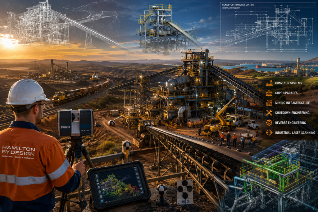
Engineering-grade 3D laser scanning and mining infrastructure project in Central Queensland, showing a conveyor transfer station, CHPP facility, coal train, industrial laser scanner, point cloud modelling and reverse engineering workflows supporting shutdown engineering and mining operations.

Example Use Case: Access Platform Modification

Shiploaders often require access improvements for inspection, maintenance and safety. This may involve stairs, platforms, handrails, ladders, guards or local structural modifications.

A scan can capture the existing structure and surrounding obstructions so that new access systems can be designed around real site conditions.

This is particularly useful when the asset has been modified over many years and the original access drawings are no longer reliable.

Example Use Case: Shutdown Planning

Shutdown time is expensive. Every hour matters.

By scanning the shiploader before the shutdown, project teams can inspect the asset digitally, measure key areas, plan removal paths, check lifting constraints, model replacement components and identify potential clashes before work begins.

This does not remove every risk, but it gives the project team better information before the asset is taken offline.

Why Engineering-Led Scanning Is Different

Not all 3D scanning is the same.

For a shiploader project, the value is not just in capturing a point cloud. The value is in understanding what the point cloud is needed for.

A survey-only approach may capture the site, but an engineering-led approach considers how the information will be used for design, fabrication, installation and maintenance.

Hamilton By Design combines LiDAR scanning with mechanical engineering, drafting and fabrication-aware modelling. That means the scan is planned around the downstream engineering outcome, not just the visual capture.

This is important for port assets because the cost of getting it wrong can be high. A small clash, incorrect bracket location, missed access constraint or outdated drawing can create real shutdown delays.

For broader mechanical design support, see our Mechanical Engineering Perth page.

FAQs

What is shiploader 3D scanning?

Shiploader 3D scanning is the process of using LiDAR scanning equipment to capture accurate three-dimensional data of a shiploader and its surrounding infrastructure. The scan creates a point cloud that can be measured, reviewed and converted into CAD models or drawings.

Why scan a shiploader before an upgrade?

A shiploader should be scanned before an upgrade because existing drawings are often outdated or incomplete. Scanning captures the real installed condition, helping engineers reduce assumptions before design, fabrication and shutdown work begins.

What parts of a shiploader can be scanned?

Hamilton By Design can scan boom structures, conveyors, transfer chutes, hoppers, guards, access platforms, stairs, handrails, wharf interfaces, drives, pulleys, services, dust control systems and surrounding port infrastructure.

Can scan data be converted into CAD drawings?

Yes. Point cloud data can be converted into 2D drawings, 3D CAD models, general arrangement drawings, sections, elevations and fabrication drawings, depending on the project requirements.

What file formats can be supplied?

Typical deliverables may include E57, RCP, RCS, LAS, DWG, STEP, SAT and Parasolid formats. The final format depends on the clientโ€™s software and required workflow.

Is shiploader scanning useful for shutdown planning?

Yes. Scanning before a shutdown helps teams check clearances, plan installation paths, identify clashes, review access and reduce the risk of discovering problems after the asset is offline.

Can 3D scanning help with chute replacement?

Yes. Chute replacement is one of the best uses for 3D scanning. The scan captures the surrounding structure, conveyor interfaces, access restrictions and existing geometry so the replacement chute can be designed with better information.

Does Hamilton By Design only work in Perth?

No. Hamilton By Design supports projects across Perth and Western Australia, including Fremantle, Kwinana, Henderson, Bunbury, Geraldton, Port Hedland, Karratha and regional bulk handling sites.

Hamilton By Design logo displayed on a blue tilted rectangle with a grey gradient background

Shiploader 3D Scanning Perth

If you are planning a shiploader upgrade, chute replacement, conveyor modification, access platform change, shutdown project or port infrastructure review, accurate as-built information is the best place to start.

Hamilton By Design provides shiploader 3D scanning Perth services for port operators, engineers, fabricators and maintenance teams working across Perth and Western Australia.

By combining engineering-grade LiDAR scanning, point cloud registration, Scan-to-CAD modelling, mechanical engineering and drafting support, Hamilton By Design helps project teams reduce assumptions, improve fabrication accuracy and plan brownfield work with greater confidence.

Contact Hamilton By Design to discuss your shiploader, conveyor, chute, wharf or port infrastructure scanning requirements.

Talk to Us – Contact Us

Name
Would you like us to arrange a phone consultation for you?
Address

Our clients:


3D Scanning and Mechanical Engineering Services Kwinana WA

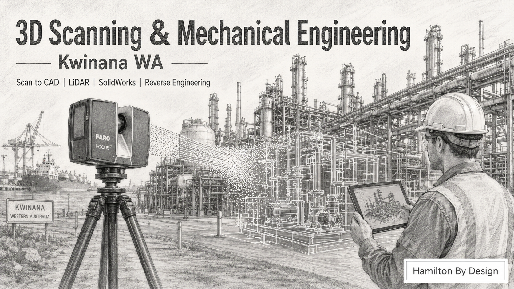
Pencil drawing of 3D scanning and mechanical engineering services in Kwinana WA, showing a FARO laser scanner, point cloud, industrial plant, CAD overlay and engineer with tablet.

Engineer-Led 3D Scanning and Mechanical Design Support for Kwinana Industry

Blue 3D LiDAR scanner icon on a tripod with scanning waves

Hamilton By Design provides 3D scanning and mechanical engineering services in Kwinana WA for industrial plants, processing facilities, workshops, fabrication companies, maintenance teams and project engineers.

Kwinana is one of Western Australiaโ€™s most important industrial areas. It supports heavy industry, bulk handling, energy, minerals processing, chemical processing, fabrication, marine services, port infrastructure and industrial maintenance. In these environments, accurate site information is essential. When existing drawings are missing, outdated or unreliable, engineering decisions become harder, slower and more expensive.

That is where 3D laser scanning, LiDAR capture and mechanical engineering design support can help.

Hamilton By Design combines site-based 3D scanning, point cloud processing, SolidWorks modelling, mechanical drafting and reverse engineering to help Kwinana businesses understand existing plant conditions before they design, modify, fabricate or install new equipment.

Whether you need accurate site measurements, as-built documentation, Scan to CAD, reverse engineering of obsolete parts, equipment layout verification or mechanical design support, we can help turn real-world site conditions into useful engineering information.

Why 3D Scanning Matters for Kwinana Industrial Sites

Industrial sites in Kwinana often contain complex plant, pipework, tanks, conveyors, platforms, structural steel, access systems, mechanical equipment and services that have changed over many years.

The problem is simple: the drawings do not always match the site.

A plant may have been modified during shutdowns. Pipework may have been rerouted. Platforms may have been added. Equipment may have been replaced. Fabricators may have worked from site measurements instead of updated drawings. Over time, the real site and the drawing register can become very different.

For brownfield projects, this creates risk.

A new chute may clash with existing steel. A replacement pump base may not line up with the real hold-down bolt locations. A platform may interfere with pipework. A new mechanical assembly may fit in CAD but fail during installation because the design was based on old information.

3D scanning reduces this risk by capturing the existing site in accurate three-dimensional detail. Instead of relying only on manual tape measurements, photos and old drawings, project teams can work from a measured point cloud of the real plant.

Common Problems We Help Solve

Hamilton By Design supports Kwinana industrial businesses with practical engineering information for real-world problems.

Common issues include:

  • Existing drawings are missing, outdated or incomplete
  • New equipment may clash with existing plant
  • Fabrication drawings are required before a shutdown
  • OEM drawings are unavailable
  • Replacement parts are expensive or have long lead times
  • Manual site measurements are difficult, unsafe or incomplete
  • Access platforms, stairs and handrails need to fit around existing equipment
  • Pipework, conveyors, tanks or structures need to be modelled from site data
  • Plant upgrades need accurate as-built information
  • Project teams need better information before approving fabrication

When the plant is complex, old or heavily modified, 3D scanning provides a better starting point.

3D Laser Scanning Services in Kwinana WA

Our 3D scanning service is designed for industrial environments where accurate measurement matters.

We can scan:

  • Processing plants
  • Pump stations
  • Conveyor systems
  • Chutes and hoppers
  • Structural steel
  • Pipe racks and pipework
  • Tanks and vessels
  • Access platforms
  • Stairs and handrails
  • Maintenance areas
  • Workshops and fabrication spaces
  • Marine and port-related infrastructure
  • Brownfield upgrade areas
  • Existing equipment layouts

The scan data can be used for design, verification, planning, fabrication, modelling and project review.

For industrial work, the value is not just the scan itself. The value comes from turning scan data into engineering information that designers, project managers, fabricators and site teams can actually use.

Scan to CAD for Kwinana Industrial Projects

Scan to CAD is the process of converting 3D scan data into CAD models, drawings or design references.

For Kwinana industrial sites, Scan to CAD can be useful when a project team needs a reliable model of existing conditions before designing new work.

Hamilton By Design can convert point cloud data into:

  • SolidWorks models
  • AutoCAD drawings
  • STEP files
  • SAT files
  • DWG files
  • DXF files
  • General arrangement drawings
  • Section views
  • Elevations
  • Fabrication references
  • Mechanical layout models
  • As-built CAD geometry

This is especially useful when working around existing plant, services and structures.

A good Scan to CAD workflow can help answer important questions before fabrication starts:

Will the new equipment fit?

Is there enough clearance?

Are the bolt locations correct?

Will the pipework clash?

Can the platform be installed safely?

Does the model match the real site?

These questions are much cheaper to answer in CAD than during installation.

Mechanical Engineering Services Kwinana WA

Hamilton By Design also provides mechanical engineering and drafting support for Kwinana businesses.

Our mechanical engineering services can include:

  • Mechanical design
  • Equipment layouts
  • Reverse engineering
  • Replacement component modelling
  • Pump and machinery component drawings
  • Fabrication drawings
  • General arrangement drawings
  • Access platform layouts
  • Chute and hopper design support
  • Conveyor-related drafting
  • Pipework drafting support
  • Brownfield modification design
  • Site measurement and verification
  • Engineering-grade CAD modelling

We work with industrial clients who need practical design support that connects the site, the CAD model and the workshop.

This is important because many industrial projects fail at the connection point between design and site reality. A drawing may look correct, but the real plant may tell a different story. By combining 3D scanning with mechanical engineering, the design process starts with better information.

Reverse Engineering for Kwinana Equipment and Parts

Many Kwinana industrial businesses operate equipment where original drawings are unavailable, the OEM no longer supports the part, or replacement lead times are too long.

Reverse engineering can help by measuring the existing component and creating a CAD model or drawing that can support replacement, repair, modification or local manufacture.

Hamilton By Design can assist with reverse engineering of:

  • Pump components
  • Shafts
  • Brackets
  • Guards
  • Covers
  • Frames
  • Mounts
  • Housings
  • Fabricated parts
  • Machined parts
  • Wear components
  • Custom plant items

Depending on the part and project requirement, reverse engineering may involve 3D scanning, manual measurement, CAD modelling, material review, tolerance consideration and production of manufacturing drawings.

This can be useful when an urgent replacement is required, when a part needs to be improved, or when site teams need to reduce reliance on unavailable OEM drawings.

Brownfield Engineering Support

Kwinana contains many brownfield industrial sites where new work must fit around existing infrastructure.

Brownfield work is difficult because there is rarely a clean, empty design space. The design must fit around what is already there.

This may include:

  • Existing structural steel
  • Pipework
  • Electrical services
  • Access ways
  • Platforms
  • Guarding
  • Tanks
  • Conveyors
  • Process equipment
  • Maintenance access zones
  • Crane access
  • Shutdown constraints

3D scanning helps create a digital record of these existing conditions. Mechanical engineering then uses that information to design practical solutions.

This can reduce the risk of rework, installation delays and fabrication changes.

Why Kwinana Businesses Use 3D Scanning Before Fabrication

Fabrication errors can be costly. If steel is fabricated from incorrect dimensions, the problem may not appear until installation. By then, the project may already be in shutdown, cranes may be booked, trades may be waiting and production may be affected.

3D scanning helps avoid this by confirming site conditions before fabrication.

For example, a scan can help check:

  • Existing steel locations
  • Floor levels
  • Equipment footprints
  • Pipework positions
  • Access clearances
  • Tank and vessel locations
  • Conveyor geometry
  • Bolt patterns
  • Existing maintenance access
  • Interface points between old and new equipment

This gives engineers and fabricators more confidence before cutting steel, ordering material or issuing drawings for manufacture.

Deliverables Available

Depending on the project, Hamilton By Design can provide:

  • Point cloud files
  • E57 files
  • RCP / RCS files
  • 3D CAD models
  • SolidWorks models
  • STEP / SAT files
  • DWG / DXF drawings
  • General arrangement drawings
  • Sections and elevations
  • Fabrication drawings
  • Reverse engineering drawings
  • Site verification reports
  • Mechanical design layouts

The right deliverable depends on the project outcome. Some clients need point cloud data. Others need a full CAD model. Some only need key interface geometry for fabrication. We can help define the right level of detail before the work begins.

Industries We Support Around Kwinana

Hamilton By Design can support industrial clients across Kwinana and surrounding areas including Rockingham, Henderson, Naval Base, Hope Valley, Cockburn, Welshpool, Canning Vale, Forrestdale and the broader Perth industrial region.

Relevant industries include:

  • Heavy industry
  • Minerals processing
  • Chemical processing
  • Energy and utilities
  • Bulk materials handling
  • Port infrastructure
  • Marine and defence support
  • Fabrication workshops
  • Mechanical contractors
  • Maintenance teams
  • Industrial construction
  • Processing plants
  • Water and wastewater infrastructure

Why Choose Hamilton By Design

Hamilton By Design is not just a scanning business. We understand mechanical engineering, drafting, fabrication, site measurement and industrial design.

This matters because a point cloud on its own does not solve every problem. The real value comes from knowing what to extract from the scan, what needs to be modelled, what needs to be drawn, and what information the workshop or project engineer needs next.

Our approach is practical:

  1. Capture the existing site conditions
  2. Process the scan data
  3. Review the engineering problem
  4. Convert the information into useful CAD or drawings
  5. Support design, fabrication or installation decisions

This helps clients move from uncertainty to usable engineering information.

3D Scanning and Mechanical Engineering for Kwinana WA

If your Kwinana project depends on accurate site information, Hamilton By Design can help.

We support industrial clients with 3D scanning, LiDAR capture, Scan to CAD, mechanical engineering, reverse engineering and drafting services across Kwinana and the wider Perth industrial region.

Whether you are planning a shutdown, replacing obsolete parts, modifying existing plant, designing new equipment or checking site conditions before fabrication, accurate 3D data can reduce risk and improve project confidence.

Hamilton By Design logo displayed on a blue tilted rectangle with a grey gradient background

Need 3D Scanning or Mechanical Engineering Support in Kwinana?

Talk to Hamilton By Design about your Kwinana industrial project.

We can assist with:

  • 3D laser scanning
  • Scan to CAD
  • Mechanical engineering
  • Reverse engineering
  • SolidWorks modelling
  • Fabrication drawings
  • Brownfield plant upgrades
  • Site verification
  • Industrial drafting

For engineering-grade 3D scanning and mechanical design support in Kwinana WA, contact Hamilton By Design.

Talk to Us – Contact Us

Name
Would you like us to arrange a phone consultation for you?
Address

Our clients:


Scan to CAD Perth

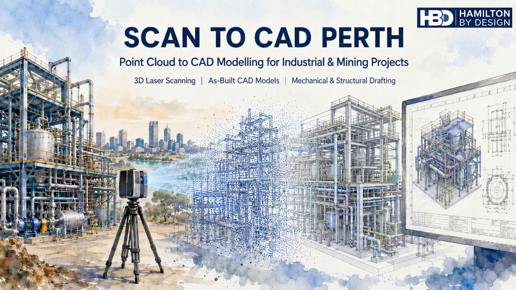
Scan to CAD Perth watercolour hero image showing a 3D laser scanner capturing an industrial plant, converting point cloud data into CAD models and engineering drawings.

Point Cloud to CAD Modelling for Industrial, Mining and Engineering Projects

Blue 3D LiDAR scanner icon on a tripod with scanning waves

Hamilton By Design provides Scan to CAD Perth services for businesses that need accurate CAD models, drawings and engineering information from existing plant, equipment, structures and sites.

Many Perth and Western Australian businesses work with assets that have been modified over many years. Drawings may be missing, outdated, incomplete or no longer trusted. This creates problems when planning upgrades, replacing equipment, modifying pipework, designing new access platforms or reverse engineering obsolete parts.

Scan to CAD helps solve this problem by converting real-world site conditions into usable CAD data.

Using 3D laser scanning and LiDAR capture, Hamilton By Design can scan existing assets and convert the point cloud into practical engineering deliverables such as 3D CAD models, 2D drawings, as-built layouts, mechanical models, structural layouts, pipework models and fabrication-ready documentation.

For related Perth services, Hamilton By Design also provides 3D laser scanning in Perth, mechanical engineering services in Perth and SolidWorks CAD support in Perth.

Our Scan to CAD Perth services support mining, industrial, manufacturing, marine, infrastructure, water, energy and process plant projects across Perth and Western Australia.


What Is Scan to CAD?

Scan to CAD is the process of capturing an existing object, machine, structure, plant room, building or industrial site using a 3D laser scanner, then converting the scan data into CAD models or drawings.

The scanner captures millions of measurement points from the real-world environment. This creates a point cloud, which can then be processed, registered and used as a reference for CAD modelling.

The CAD output may be simple or detailed depending on the project.

For example, a business may need a basic 3D layout to check whether new equipment will fit. Another project may require detailed CAD models of pipework, steelwork, access platforms, pump components or mechanical assemblies. In some cases, the final deliverable may be a set of fabrication drawings, general arrangement drawings, sections, elevations or 3D model files for engineering design.

Scan to CAD is especially useful for brownfield projects, where new design work needs to fit around existing assets.


Why Perth Businesses Use Scan to CAD Services

Perth businesses use Scan to CAD services when they need reliable information about existing assets.

This is common in mining, ports, processing plants, fabrication workshops, pump stations, utilities, marine facilities and industrial sites. Many of these sites have been changed over many years. Equipment has been replaced, pipework has been rerouted, structures have been modified and old drawings may not reflect the current condition.

When drawings cannot be trusted, engineering work becomes risky.

A new piece of equipment may clash with existing steelwork. A replacement pipe spool may not fit. A platform may be designed around incorrect dimensions. A shutdown job may be delayed because the site information was wrong. These problems can cost far more than the original drafting or scanning work.

Scan to CAD helps reduce this risk by giving engineers, project managers, fabricators and maintenance teams a clearer understanding of the existing site before design, fabrication or installation begins.

For larger Perth and WA projects, this service can also connect with Hamilton By Designโ€™s broader Perth WA engineering and 3D scanning services.


Common Problems Scan to CAD Helps Solve

One of the biggest problems businesses face is the lack of reliable drawings. In many industrial environments, original drawings are either unavailable or no longer accurate. This is particularly common where plant has been upgraded over many years without the as-built documentation being updated.

Another common problem is that OEM drawings are not available. Equipment suppliers may not provide drawings, or replacement parts may have long lead times and high costs. In these situations, Scan to CAD can assist with reverse engineering by capturing the existing part or assembly and creating CAD models for review, repair, modification or replacement.

Brownfield upgrades are another major reason for using Scan to CAD. Existing structures, conveyors, chutes, tanks, pumps, platforms, walkways and pipework can make new design work difficult. A scan provides a practical way to model the existing environment and check the proposed design before fabrication.

Shutdown work is also a key driver. During a shutdown, there is limited time to complete installation work. If a fabricated part does not fit, the cost can be significant. Scan to CAD helps reduce the chance of site rework, emergency fabrication and installation delays.


Scan to CAD for Mining and Industrial Sites in Perth

Perth is closely connected to Western Australiaโ€™s mining, resources, marine, energy and industrial sectors. Many projects are designed, managed or supported from Perth, even when the site itself is located elsewhere in WA.

Hamilton By Design supports Scan to CAD services for mining and industrial applications including:

Conveyors, chutes and transfer points.

Pump stations and pipework.

Processing plants and fixed plant equipment.

Access platforms, stairs, ladders and walkways.

Structural steel layouts.

Mechanical equipment and machine components.

Plant rooms and service areas.

Marine and ship repair projects.

Brownfield upgrade areas.

Reverse engineering of obsolete or unavailable parts.

The purpose is not only to create a point cloud. The purpose is to turn that scan data into useful engineering information.

For projects involving steelwork, platforms, pipework or industrial layouts, Hamilton By Design also provides mechanical, structural and pipework drafting in Perth WA.


From Point Cloud to Practical CAD Deliverables

A point cloud is valuable, but many businesses need more than raw scan data. They need usable CAD information that can support decisions, design work, procurement, fabrication and installation.

Hamilton By Design can convert point cloud data into a range of CAD deliverables, including:

3D CAD models.

2D CAD drawings.

General arrangement drawings.

Sections and elevations.

As-built layouts.

Pipework models.

Structural models.

Mechanical models.

STEP, SAT or Parasolid files.

SolidWorks models.

Inventor models.

AutoCAD drawings.

DWG and DXF files.

Fabrication drawings where required.

The final deliverable depends on the project requirement. A clash detection model may not need the same level of detail as a fabrication drawing. A concept model may not need every bolt and weld. A reverse engineering job may need a much higher level of detail.

This is why it is important to define the scope before scanning and modelling begins.


The Importance of Engineering Understanding

Scan to CAD is not just a software process. It requires engineering judgement.

A scanner records what it can see, but the CAD model needs to be interpreted and built by someone who understands the purpose of the work. This is especially important for mechanical, structural and industrial projects.

For example, pipework may need to be modelled using correct pipe outside diameters and centre lines. Steelwork may need to reflect real member sizes. Platforms and access systems may need to consider Australian Standards such as AS 1657. Mechanical components may need to be modelled with design intent, clearances, tolerances and manufacturing method in mind.

A visually impressive model is not always an engineering-ready model.

Hamilton By Design focuses on practical CAD outputs that can be used by engineers, fabricators, project managers and maintenance teams.


Problems Businesses Can Have With Poor Scan to CAD Services

Not all Scan to CAD services are the same.

A common problem is that businesses receive a large point cloud but do not know how to use it. The file may be too large, the format may not suit their software, or the areas they need may not have been captured properly.

Another problem is unclear scope. If the instruction is only โ€œscan the site and provide CADโ€, the result may not match what the business expected. The scope should define what needs to be scanned, what needs to be modelled, the required level of detail, the accuracy expectations, the required file formats and whether drawings are included.

Businesses can also run into trouble when the model is either under-modelled or over-modelled. Under-modelling can miss important details. Over-modelling can waste time and increase cost without adding value.

There can also be line-of-sight issues. Laser scanners cannot see through objects, insulation, guards, cladding or equipment. Hidden areas may require extra scan positions, physical measurement or site verification.

The best results come from planning the scan around the final CAD deliverable.


When Should Scan to CAD Be Used?

Scan to CAD should be considered early in a project, especially when existing information is unreliable.

It is useful before:

Plant upgrades.

Equipment installation.

Shutdown planning.

Pipework replacement.

Structural modification.

Access platform design.

Reverse engineering.

Fabrication.

Clash detection.

Layout planning.

As-built documentation.

The earlier the scan is completed, the more useful it becomes. If the scan is done after design work is already finished, it may only reveal problems late in the project. When scanning is completed early, the design team can work around the real site conditions from the start.


Scan to CAD Perth for Brownfield Engineering

Brownfield engineering is one of the strongest applications for Scan to CAD.

In a brownfield site, the challenge is not simply designing something new. The challenge is making sure the new design fits the existing plant.

This is where Scan to CAD provides value.

By converting existing site conditions into CAD, Hamilton By Design can help identify space restrictions, clashes, tie-in points, access limitations and installation constraints before work reaches site.

This can support better planning, better design decisions and reduced installation risk.

For businesses needing building, facility or infrastructure modelling from scan data, Hamilton By Design also provides Scan to BIM services in Perth WA.


Why Work With Hamilton By Design?

Hamilton By Design combines 3D laser scanning, CAD modelling, mechanical engineering, structural drafting and reverse engineering experience.

This means the Scan to CAD process is approached with the final engineering outcome in mind.

We understand that businesses do not simply need a scan. They need answers.

Will the new equipment fit?

Can the part be reverse engineered?

Can the pipework be modelled accurately?

Can the existing structure be documented?

Can the shutdown risk be reduced?

Can the CAD model be used for design, drafting or fabrication?

Our goal is to provide practical CAD information that helps businesses make better engineering decisions.


Scan to CAD Perth Services

Hamilton By Design provides Scan to CAD Perth services for businesses needing accurate, useful and engineering-focused CAD deliverables from existing assets.

Whether the project involves mining equipment, industrial plant, pipework, structural steel, mechanical components, marine repairs or brownfield upgrades, Scan to CAD can help turn site reality into usable engineering data.

If your business has missing drawings, unreliable site information, obsolete parts, shutdown risk or brownfield design challenges, Scan to CAD may be the right starting point.

Hamilton By Design can assist with 3D laser scanning, point cloud processing, CAD modelling, as-built documentation and engineering drafting for Perth and Western Australian projects.

Hamilton By Design logo displayed on a blue tilted rectangle with a grey gradient background

Need Scan to CAD Support in Perth?

Hamilton By Design provides Scan to CAD services for Perth businesses that need accurate CAD models and drawings from existing plant, equipment and structures.

We can assist with site scanning, point cloud processing, CAD modelling, as-built drawings, reverse engineering and engineering documentation for industrial and mechanical projects.

Talk to Us – Contact Us

Name
Would you like us to arrange a phone consultation for you?
Address

Our clients:

Open Cut Mine Machinery Reverse Engineering Muswellbrook NSW

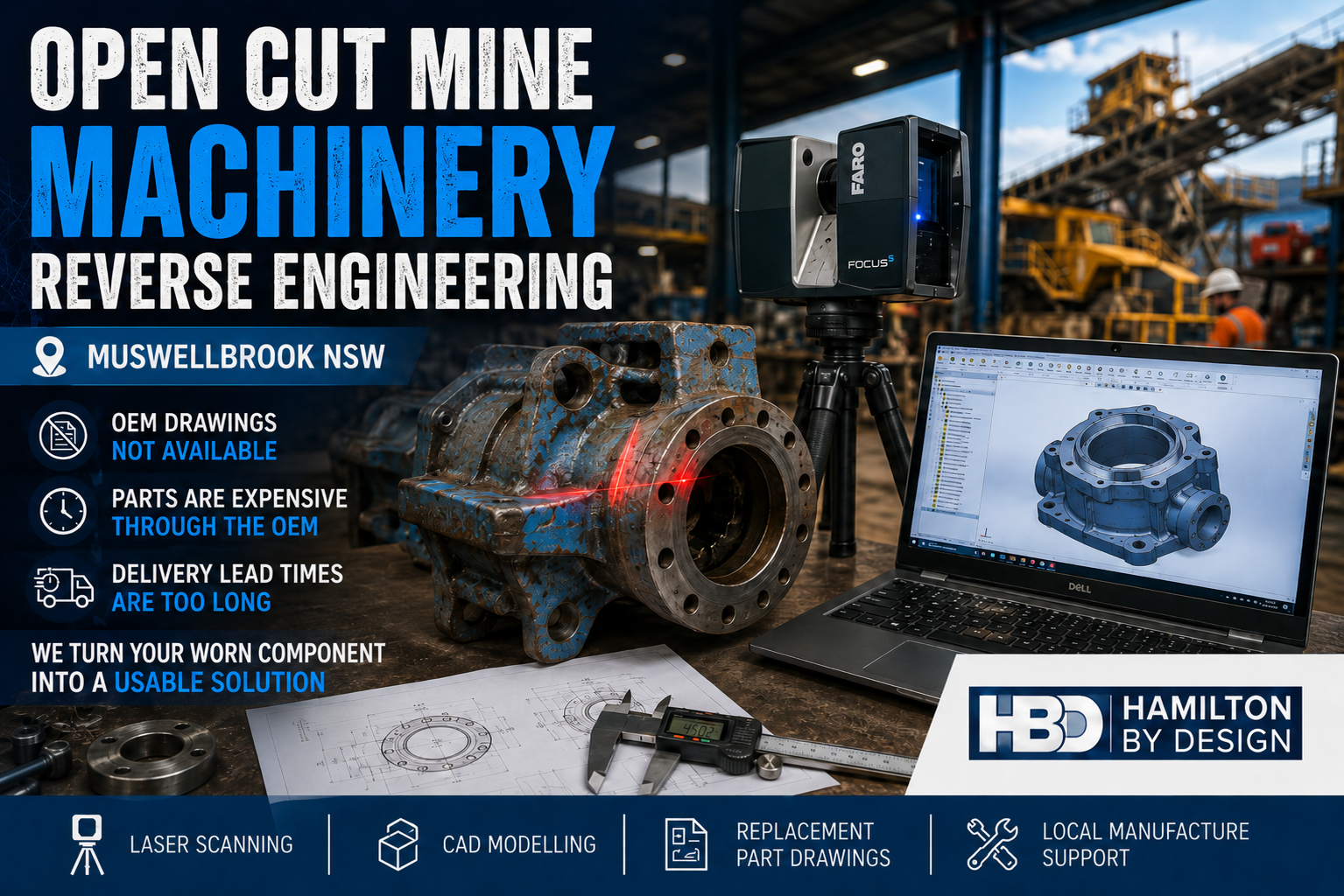
Open cut mine machinery reverse engineering image showing a worn mining component being laser scanned beside a CAD model, with Hamilton By Design branding and Muswellbrook NSW text.

Replacement Parts Without OEM Drawings, Long Lead Times or Excessive OEM Costs

Open cut mining operations around Muswellbrook NSW rely on heavy machinery, fixed plant, conveyors, crushers, feeders, pumps, screens, chutes, hoppers, guards, frames and access systems to keep production moving.

When a critical machinery component wears out, cracks, fails or becomes obsolete, the first option is often to contact the original equipment manufacturer.

But for many mining maintenance teams, that creates a serious problem.

The OEM may not provide detailed drawings.
The replacement part may be expensive.
The delivery lead time may be too long.
The machine may be older, modified or no longer fully supported.

This can leave mine operators, maintenance teams and shutdown planners with limited options when they need a replacement part quickly.

Hamilton By Design supports open cut mining operations, maintenance teams, fabricators and repair workshops with engineering-grade 3D laser scanning and mining plant upgrade support, reverse engineering, CAD modelling and engineering documentation for mine machinery components.

Our focus is not open cut pit scanning or mine survey work. Our focus is machinery, fixed plant, replacement parts and brownfield equipment support.

If a component can be removed, measured, scanned or inspected, it may be possible to develop a 3D CAD model, manufacturing drawing or replacement part design that supports local manufacture, repair or redesign.


The Real Problem: OEM Drawings Are Not Available

For many mining assets, the biggest problem is not always that old site drawings are outdated. The larger problem is that the equipment owner often does not have access to the detailed OEM drawings required to reproduce or repair the part.

The mine may own the machine.

The maintenance team may own the worn component.

The workshop may be able to manufacture a replacement.

But without the correct drawings, dimensions, tolerances, materials and fit-up information, the replacement process becomes difficult.

This is a common problem with:

  • Older mining machinery
  • Imported equipment
  • Obsolete parts
  • Proprietary OEM components
  • Modified equipment
  • Worn mechanical assemblies
  • Shutdown-critical replacement parts
  • Components with long supply lead times
  • Parts that are too expensive through the OEM supply chain

When a part is urgently needed, waiting weeks or months for an imported OEM replacement may not be practical. In some cases, the part cost may also be difficult to justify, especially when a local fabrication or machining solution may be possible.

Reverse engineering provides another pathway.


What Is Mine Machinery Reverse Engineering?

Mine machinery reverse engineering is the process of capturing the geometry, features and function of an existing component so that a usable CAD model, drawing or replacement design can be created.

This may involve laser scanning, manual measurement, inspection, CAD modelling and engineering review.

The aim is to understand the part well enough to support repair, manufacture, fit-up or redesign.

Depending on the component, this may include:

  • Measuring critical diameters
  • Capturing bolt hole patterns
  • Checking shaft, bush and bearing fits
  • Modelling flanges, brackets and housings
  • Recording wear surfaces
  • Capturing complex cast shapes
  • Creating 3D CAD models
  • Producing 2D manufacturing drawings
  • Identifying practical fabrication methods
  • Supporting local machining, fabrication or casting

Reverse engineering is especially useful where the original drawings are not available from the OEM, or where the part has been modified during its service life.

Hamilton By Design also provides replacement part reverse engineering where OEM drawings are unavailable, helping asset owners move from a physical component to usable manufacturing information.


Why This Matters for Muswellbrook Mining Operations

Muswellbrook and the surrounding Upper Hunter region support major mining, industrial maintenance and heavy equipment operations. Open cut mine machinery is exposed to harsh operating conditions, heavy loads, vibration, dust, impact, abrasion and constant production pressure.

When machinery components fail, the issue is rarely simple.

A replacement part may be required urgently.

The part may need to fit into an existing machine.

The equipment may be old or modified.

The OEM may have a long delivery time.

The replacement price may be high.

The mine may need a local repair or manufacturing option.

This is where laser scanning and reverse engineering can assist. Instead of relying only on unavailable OEM drawings, the existing component can be captured, measured and converted into usable engineering information.

That information can then support local manufacturing, repair, redesign or future asset documentation.

For mining operators, contractors and industrial clients across the region, Hamilton By Design provides Hunter Valley mining engineering and 3D laser scanning services focused on practical brownfield plant, machinery and materials handling problems.


Common Machinery Parts That May Be Reverse Engineered

Hamilton By Design can assist with reverse engineering and CAD documentation for a range of mine machinery and fixed plant components.

Examples include:

  • Pump components
  • Bearing housings
  • Drive components
  • Couplings
  • Guards and covers
  • Conveyor components
  • Chute components
  • Hopper parts
  • Wear liners
  • Brackets and mounts
  • Structural frames
  • Shafts and sleeves
  • Flanges and adaptors
  • Fabricated assemblies
  • Cast components
  • Obsolete machine parts
  • Modified equipment parts

Some parts require high-detail measurement. Others require practical engineering judgement to determine which features are critical and which features can be simplified for manufacture.

The goal is not always to create a perfect visual copy of the original part. The goal is to create useful engineering information that allows the replacement part to be manufactured, fitted and used safely.


How Laser Scanning Helps

Laser scanning is useful when a component has complex geometry, difficult-to-measure surfaces or no existing CAD model.

A laser scanner captures the visible surfaces of the part as a point cloud. This data can then be used as a reference for CAD modelling and dimensional checking.

Laser scanning can be especially useful for:

  • Castings
  • Worn parts
  • Complex housings
  • Curved surfaces
  • Irregular shapes
  • Large fabricated items
  • Assemblies with multiple interfaces
  • Parts where manual measurement alone is slow or difficult

However, laser scanning is only one part of the process.

For machinery reverse engineering, critical dimensions still need to be understood. Bearing fits, shaft fits, bolt holes, machined faces, threads, splines, sealing surfaces and alignment features may require additional measurement and engineering review.

That is why Hamilton By Design combines laser scanning with practical mechanical design and CAD modelling experience.


The Reverse Engineering Workflow

A typical reverse engineering workflow may include the following steps.

1. Identify the Part and the Problem

The first step is to understand what the part does and why it needs to be replaced.

Questions may include:

  • Is the part worn, cracked, broken or obsolete?
  • Is the part required for a shutdown?
  • Is the OEM replacement too expensive?
  • Is the lead time too long?
  • Is the part being repaired, copied or improved?
  • Does the replacement need to match the original exactly?
  • Are there known fit-up issues with the existing machine?

Understanding the problem helps determine the correct level of measurement and modelling.

2. Inspect and Measure the Component

The component is inspected and measured. This may include laser scanning, manual measurement, photographs, sketches and notes.

Critical features may include:

  • Bolt hole centres
  • Mounting faces
  • Shaft diameters
  • Bearing locations
  • Overall envelope size
  • Mating faces
  • Wear surfaces
  • Clearance areas
  • Welded or machined details
  • Material thicknesses
  • Assembly interfaces

Where a part is worn, care is needed. The worn shape may not represent the original working geometry. In these cases, engineering judgement may be required to determine the intended size or fit.

3. Create a 3D CAD Model

The measured data is used to create a 3D CAD model.

This model may be developed in SolidWorks, Inventor or another suitable CAD platform. The model can be used to check geometry, confirm fit-up and prepare manufacturing information.

Depending on the job, the model may represent:

  • A single component
  • A machined part
  • A fabricated assembly
  • A casting
  • A guard or cover
  • A chute section
  • A pump component
  • A machine frame
  • A modified replacement design

Hamilton By Design provides 3D CAD modelling for mining, heavy industry and mechanical plant projects, helping convert site measurements, scans, sketches and physical components into practical engineering models.

The model can also be exported in common formats such as STEP, SAT or Parasolid for use by fabricators, machinists or other engineering teams.

4. Produce Manufacturing Drawings

Once the model is complete, 2D drawings can be created for manufacture.

These drawings may include:

  • General dimensions
  • Critical fit dimensions
  • Hole patterns
  • Machined faces
  • Material notes
  • Weld details
  • Fabrication notes
  • Assembly details
  • Tolerance requirements
  • Surface finish requirements where needed

The level of drawing detail should suit the manufacturing process. A fabricated guard does not need the same detail as a machined bearing housing. A cast component may require different information again.

5. Review Fit-Up and Future Use

The replacement part can then be checked against the original component, mating parts or surrounding machine geometry.

Where needed, the CAD data can also be stored for future use. This gives the asset owner better control over future replacement, repair or redesign work.

Once the part has been reverse engineered, the mine is no longer starting from zero the next time that component is required.


Benefits of Reverse Engineering Mine Machinery Parts

Reverse engineering can provide several practical benefits for mine operators, maintenance teams and fabrication workshops.

Reduced Dependence on OEM Drawings

When the OEM will not provide drawings, reverse engineering can create the missing technical information needed to support local manufacture or repair.

Shorter Lead Times

If a local fabricator or machine shop can manufacture the part, the project may avoid long OEM supply delays.

Better Cost Control

OEM replacement parts can be expensive. Reverse engineering can help identify whether local manufacture, repair or redesign is a practical alternative.

Support for Obsolete Equipment

Older machinery may no longer be fully supported. Reverse engineering helps extend the life of useful assets where replacement parts are difficult to obtain.

Improved Shutdown Planning

Having drawings and CAD models ready before a shutdown can reduce uncertainty and improve planning.

Future Asset Control

Once the part is modelled and documented, the mine has better information for future maintenance, procurement and engineering decisions.


Not Every Part Should Be Copied Without Review

Reverse engineering does not mean blindly copying every worn or damaged part.

Some parts are safety critical. Some parts are highly loaded. Some parts may have fatigue, wear, material or heat treatment requirements. Some components may be subject to compliance, certification or OEM warranty considerations.

That means each part should be reviewed properly before manufacture.

In some cases, the best approach may be:

  • Direct replacement
  • Repair
  • Redesign
  • Strength improvement
  • Material upgrade
  • Manufacturing process change
  • Additional engineering verification
  • FEA or stress review
  • Supplier review
  • Third-party certification

Hamilton By Design can assist with the engineering documentation and CAD modelling needed to support these decisions.


Tools Used by Hamilton By Design

Hamilton By Design uses a practical mix of scanning, modelling and engineering tools to support machinery reverse engineering projects.

These may include:

  • FARO Focus laser scanning
  • FARO SCENE point cloud processing
  • Manual measurement and inspection
  • SolidWorks CAD modelling
  • Autodesk Inventor modelling
  • AutoCAD drafting
  • STEP, SAT and Parasolid export
  • 2D manufacturing drawings
  • Assembly drawings
  • Fabrication drawings
  • Design verification
  • SolidWorks Simulation or FEA support where required

The right tools depend on the part, the accuracy required and the manufacturing method.


Why Work With Hamilton By Design?

Hamilton By Design combines site measurement, laser scanning, mechanical design, CAD modelling and practical manufacturing experience.

This is important because mine machinery reverse engineering is not just a scanning exercise.

A scan can capture shape.

But the engineering process must also understand fit, function, manufacturing method, tolerances, material selection, access, assembly and maintenance requirements.

Hamilton By Design can support:

  • Mine operators
  • Maintenance teams
  • Shutdown planners
  • Reliability engineers
  • Fabricators
  • Machine shops
  • Repair workshops
  • Industrial contractors

For Muswellbrook and Upper Hunter mining operations, this service is aimed at machinery and fixed plant problems where the OEM pathway is too slow, too expensive or too restrictive.


Open Cut Mine Machinery Reverse Engineering in Muswellbrook NSW

If your mining operation has a worn, damaged or obsolete machinery component and the OEM will not supply drawings, Hamilton By Design can help create practical engineering information from the existing part.

We can assist with laser scanning, reverse engineering, CAD modelling and manufacturing drawings for mine machinery and fixed plant components.

This can help reduce reliance on OEM supply chains, support local manufacture and improve control over future maintenance.


Hamilton By Design logo displayed on a blue tilted rectangle with a grey gradient background

Need Replacement Part Drawings Without OEM Support?

Hamilton By Design provides reverse engineering and CAD modelling support for mine machinery components in Muswellbrook, the Upper Hunter and across NSW.

If the OEM will not provide drawings, the lead time is too long or the replacement part cost is too high, reverse engineering may provide a practical path forward.

Contact Hamilton By Design to discuss machinery laser scanning, reverse engineering, CAD modelling and replacement part documentation for mining equipment and fixed plant components.

Talk to Us – Contact Us

Name
Would you like us to arrange a phone consultation for you?
Address

Our clients: