Drafting Capacity for Todayโ€™s Projects: An Integrated Scan โ†’ Model โ†’ Detail โ†’ Check Workflow

Drafting Capacity for Todayโ€™s Projects | Engineering-Led Documentation

Engineering and construction projects are increasingly delivered under compressed timeframes, constrained resources, and heightened compliance expectations. In this environment, access to reliable drafting capacityโ€”supported by robust processesโ€”is critical to maintaining quality and reducing project risk.

Hamilton By Design provides experienced drafting capacity, available for short-term support or longer-term secondment, delivered within a structured scan โ†’ model โ†’ detail โ†’ check workflow that aligns documentation with real-world conditions and engineering intent.


Drafting capacity aligned with contemporary project demands

Modern projects often require drafting support that can scale quickly to address:

  • Peak workloads during design development or shutdown preparation
  • Short-term resourcing gaps within engineering teams
  • Documentation demands driven by upgrades, modifications, or compliance works
  • Brownfield environments where existing information is incomplete or unreliable

In these situations, drafting capacity must be more than transactional. It must integrate with engineering workflows and reflect current site conditions.


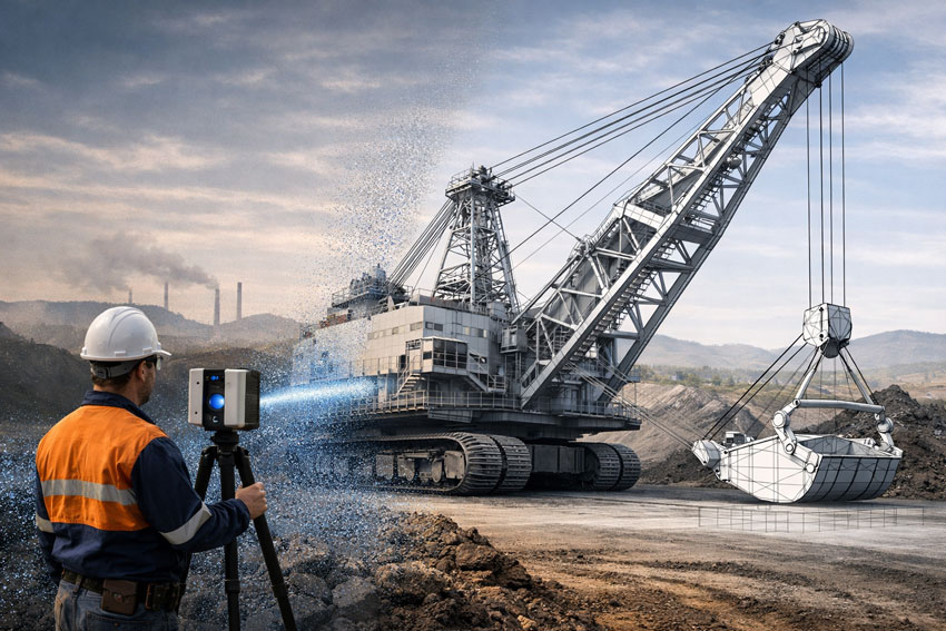
Scan: establishing an accurate technical baseline

Where existing drawings cannot be relied upon, accurate documentation begins with engineering-grade reality capture.

Our team utilises 3D laser scanning to establish a defensible geometric baseline of existing assets. This approach supports drafting activities by ensuring that models and drawings are developed from verified site data, rather than assumptions or legacy documentation.


Model: structured CAD developed for engineering use

Scan data is translated into purpose-built CAD models, developed to suit the intended engineering and documentation outcomes. Models are structured with appropriate datums, tolerances, and levels of detail to support:

  • Engineering assessment and design coordination
  • Structural and mechanical detailing
  • As-built documentation and future modification

This modelling stage ensures drafting activities are grounded in usable, engineering-aligned data.


Detail: producing clear, buildable documentation

Drafting output remains one of the most critical interfaces between design and construction.

From verified models, our draftspersons produce clear, fabrication-ready drawings that communicate engineering intent accurately and unambiguously. Documentation is prepared with consideration for:

  • Constructability and sequencing
  • Fabrication practicality
  • Coordination between disciplines
  • Alignment with relevant Australian Standards

The emphasis is on documentation that can be confidently issued to site.


Check: verification as a formal step, not an afterthought

Before issue, drawings and models are subject to structured review to confirm:

  • Consistency with scan data and models
  • Coordination across views and drawing sets
  • Technical clarity and buildability

This checking step reduces the likelihood of downstream rework and supports defensible documentation outcomes.


Why integrated drafting capacity matters

When drafting is separated from scanning, modelling, or checking, risk is introduced at each handover.

An integrated scan โ†’ model โ†’ detail โ†’ check workflow:

  • Improves documentation reliability
  • Reduces errors caused by assumptions
  • Supports compliance and verification
  • Enhances confidence during fabrication and construction

This approach is particularly effective for existing assets, industrial facilities, and brownfield upgrades.


Flexible drafting support and secondment

Hamilton By Designโ€™s drafting capacity can be provided as:

  • Short-term drafting support
  • Longer-term secondment within client teams
  • Targeted assistance during high-demand project phases

Drafting support is delivered within an engineering-led environment, ensuring alignment between documentation and technical intent.

To learn more about flexible resourcing options, visit our Secondment Services page:
๐Ÿ‘‰ https://www.hamiltonbydesign.com.au/home/secondment-services/


Hamilton By Design logo displayed on a blue tilted rectangle with a grey gradient background

Conclusion

As project complexity and delivery pressures continue to increase, drafting capacity must be current, integrated, and accountable.

By providing experienced draftspersons supported by a structured scan โ†’ model โ†’ detail โ†’ check workflow, Hamilton By Design enables project teams to scale documentation capability without compromising accuracy, buildability, or engineering quality.

Name
Would you like us to arrange a phone consultation for you?
Address

What Is the Difference Between a Terrestrial Scanner and a LiDAR Scanner?

Terrestrial, mobile SLAM and drone LiDAR scanners capturing an industrial plant with engineers reviewing point cloud data and drawings

Terrestrial vs LiDAR Scanners | Whatโ€™s the Difference?

Confusion around terrestrial scanning and LiDAR scanning is common โ€” and understandable.
The two terms are often used interchangeably, even though they describe different things.

This page explains the difference in plain language, shows where each approach fits, and helps you decide what level of accuracy and risk is appropriate for your project.


Short Answer (If Youโ€™re in a Hurry)

LiDAR describes the laser measurement technology.
Terrestrial describes how and where that LiDAR scanner is deployed.

Most terrestrial scanners use LiDAR, but not all LiDAR scanners are terrestrial.


Illustration comparing terrestrial LiDAR, mobile SLAM LiDAR and drone scanning on an industrial facility

What Is LiDAR?

LiDAR (Light Detection and Ranging) is a method of measuring distance using laser light.

How LiDAR works

  • A laser pulse is emitted
  • The pulse reflects off an object
  • The return time is measured
  • Distance is calculated and stored as a 3D point

Millions of these points form a point cloud that represents real-world geometry.

What LiDAR is good for

  • Accurate 3D measurement
  • Complex geometry
  • Low-light or enclosed environments
  • Engineering, construction, and industrial sites

LiDAR answers: How is distance measured?


What Is a Terrestrial Scanner?

A terrestrial scanner is a ground-based scanning system, usually mounted on a tripod or fixed position.

Key characteristics

  • Fixed scan position
  • Controlled setup and coverage
  • Known geometry and reference
  • High repeatability and validation

Typical environments

  • Processing plants and CHPPs
  • Structural steelwork
  • Conveyor systems
  • Brownfield tie-ins
  • As-built verification
  • Shutdown-critical fit-up work

Terrestrial answers: Where and how is the LiDAR deployed?


How the Two Terms Relate (This Is the Important Part)

A terrestrial scanner is a platform.
A LiDAR scanner is a technology.

Most modern terrestrial scanners are terrestrial LiDAR scanners.

Example: a tripod-mounted system such as the FARO Focus S-Series is:

  • LiDAR-based (laser measurement)
  • Terrestrial (ground-based, fixed setup)

Other Common LiDAR Scanner Types (And Why It Matters)

Scanner TypeHow Itโ€™s UsedTypical Outcome
Terrestrial LiDARTripod / fixedHighest control & accuracy
Mobile / SLAM LiDARHandheld / walk-throughFast capture, lower control
Vehicle-mounted LiDARCar / trolleyCorridor mapping
Aerial LiDARDrone / aircraftLarge areas, low detail

All are โ€œLiDARโ€, but not all are suitable for engineering design or fabrication.


Why This Distinction Matters for Projects

Many issues occur when:

  • A LiDAR scan is assumed to be engineering-grade
  • A mobile or SLAM scan is used beyond its intent
  • Accuracy, validation, or limitations are not clearly understood

This doesnโ€™t mean one method is wrong โ€” it means each has a purpose.

The key is aligning the scanner type with:

  • Required accuracy
  • Risk tolerance
  • Fit-up criticality
  • Intended use of the data

Our clients:


Simple Decision Guide (Client in Control)

If you need:

  • Fabrication or replacement parts โ†’ Terrestrial LiDAR
  • Shutdown-critical fit-up โ†’ Terrestrial LiDAR
  • Structural verification โ†’ Terrestrial LiDAR
  • Rapid site context only โ†’ Mobile / SLAM LiDAR
  • Large terrain or stockpiles โ†’ Aerial LiDAR

There is no โ€œone best scannerโ€ โ€” only the right scanner for the outcome you want.


Comparison at a Glance

RequirementTerrestrial LiDARMobile / SLAM LiDAR
Accuracy controlHighModerate
RepeatabilityHighLower
Engineering defensibilityStrongLimited
Fit-up confidenceSuitableNot recommended
Capture speedSlowerFaster
Best use caseDesign & fabricationVisualisation & context

A Note on Engineering Use

Where scanning data feeds into engineering design, documentation, or fabrication, higher-control methods are typically required to align with engineering practice and Australian Standards expectations.

That doesnโ€™t remove choice โ€” it simply means the assumptions and limitations must match the intended use.


How We Approach This (Without Locking You In)

Weโ€™re happy to:

  • Work with terrestrial, mobile, or supplied scan data
  • Validate data before design where required
  • Align scanning effort with your risk, budget, and outcome
  • Clearly document assumptions and limitations

You stay in control of the approach โ€” our role is to make sure the data supports the outcome you expect.


Hamilton By Design logo displayed on a blue tilted rectangle with a grey gradient background

Next Step

If youโ€™re unsure which scanning method suits your project:

Fill out the contact form and tell us:

  • What you want to build, replace, or verify
  • How the data will be used
  • Any constraints (budget, time, shutdown windows)

Weโ€™ll help you select a fit-for-purpose scanning approach, not just a scanner.


Name
Would you like us to arrange a phone consultation for you?
Address

Hunter Valley Laser Scanning | CAD-Ready SolidWorks & Inventor

Engineering-grade LiDAR scanning of a dragline at a Hunter Valley mine producing CAD-ready data for SolidWorks and Autodesk Inventor

Hunter Valley Laser Scanning | CAD-Ready SolidWorks & Inventor

Engineering-Grade 3D & LiDAR Scanning Built for SolidWorks & Autodesk Inventor

The Hunter Valley is home to critical mining, power generation, manufacturing, and heavy-industry assets. In these environments, laser scanning is only valuable if the data can be used directly in engineering design software.

At Hamilton By Design, we deliver Hunter Valley laser scanning services that are purpose-built for engineering workflows โ€” ensuring scan data can be reliably used in SolidWorks and Autodesk Inventor without rework, approximation, or loss of accuracy.


Why โ€œScan-Onlyโ€ Data Is a Problem

Many laser scanning services focus on data capture only. While the point cloud may look impressive, it often fails at the most important step:

Can the scan be used directly in CAD and engineering design?

If the answer is no, the scan has limited value.

Common issues with low-grade or technician-only scanning include:

  • Point clouds that are not registered or scaled correctly
  • Insufficient accuracy for mechanical design tolerances
  • Poor alignment to real-world coordinate systems
  • Data that cannot be reliably modelled in SolidWorks or Inventor
  • Extra time and cost spent โ€œfixingโ€ scan data before design can begin

Why would you spend money on a scan that cannot be used for engineering?


Engineer performing engineering-grade laser scanning of a dragline excavator at a Hunter Valley mine for SolidWorks and Autodesk Inventor design

Engineering-Grade Laser Scanning โ€” Designed for CAD Use

Hamilton By Design approaches laser scanning as an engineering input, not a visual deliverable.

Our Hunter Valley laser scanning services are planned and executed so that scan data can be:

  • Used directly in SolidWorks
  • Imported and referenced accurately in Autodesk Inventor
  • Modelled into fabrication-ready geometry
  • Trusted for mechanical, structural, and layout decisions

This means the scan is not the end product โ€” it is the foundation for engineering and design.


Why Scanner Capability Matters

Not all scanners โ€” or scanning providers โ€” are equal.

Low-accuracy or inappropriate scanning equipment can result in:

  • Global accuracy drift
  • Poor definition of critical interfaces
  • Inability to confidently model mating parts, pipework, or steelwork
  • Designs that โ€œlook rightโ€ on screen but fail on site

Hamilton By Design uses engineering-grade scanning equipment and workflows, ensuring the captured data supports:

  • Mechanical equipment upgrades
  • Structural modifications
  • Conveyor, chute, and platform design
  • Fabrication and installation planning

Hunter Valley Applications Where CAD-Ready Scans Matter

Mining & CHPP Upgrades

Laser scanning of conveyors, transfer stations, chutes, and structures that must integrate precisely with new mechanical equipment.

Power Generation & Utilities

Accurate capture of plant rooms, pipework, platforms, and access systems for compliance and upgrade works.

Manufacturing & Heavy Industry

Reliable spatial data to support machinery installation, relocation, and layout optimisation.

Brownfield Construction & Retrofits

Engineering-grade scans to avoid clashes, rework, and costly shutdown overruns.


Engineer-Led Scanning โ€” Not Just Data Capture

At Hamilton By Design, laser scanning is delivered by engineers who understand how the data will be used.

This ensures:

  • Scan resolution and accuracy are matched to design intent
  • Critical interfaces are captured correctly
  • Data integrates seamlessly with CAD workflows
  • Accountability is maintained from scan through to design and documentation

You donโ€™t just receive a point cloud โ€” you receive usable engineering data.


Deliverables That Engineers Can Actually Use

Depending on your project, we provide:

  • Registered, engineering-grade point clouds
  • CAD-ready reference data for SolidWorks and Inventor
  • Section views and alignment references
  • Models and drawings derived directly from scan data
  • Documentation suitable for fabrication and construction

Everything is scoped so the scan adds value immediately, not later after rework.


Hunter Valley Laser Scanning โ€” Designed to Be Used, Not Admired

Laser scanning should remove uncertainty, not create more work.

By ensuring scan data can be used directly in SolidWorks and Autodesk Inventor, Hamilton By Design helps Hunter Valley projects move from site capture to design, fabrication, and installation with confidence.

Hamilton By Design delivers engineering-grade laser scanning in the Hunter Valley โ€” built for real engineering outcomes, not just visualisation.

Contact us to discuss your Hunter Valley laser scanning requirements or arrange an engineering-led site scan.

Name
Would you like us to arrange a phone consultation for you?
Address

3D Construction Scanning Darwin

Engineering-grade 3D laser scanner capturing Darwin port infrastructure, harbour assets, and urban skyline

Engineering-Grade LiDAR for Accurate As-Built & Construction Delivery

Construction projects in Darwin operate in a demanding environment โ€” tropical weather, remote logistics, accelerated schedules, and complex interfaces between structural, mechanical, and architectural elements. 3D construction scanning provides a reliable digital foundation to reduce risk, eliminate rework, and support confident decision-making throughout the project lifecycle.

Hamilton By Design delivers engineering-grade 3D construction scanning in Darwin, supporting contractors, engineers, builders, and asset owners with accurate spatial data, as-built models, and construction-ready documentation.

๐Ÿ‘‰ Learn more about our Darwin scanning capability:
https://www.hamiltonbydesign.com.au/3d-scanning-in-darwin/
https://www.hamiltonbydesign.com.au/home/engineering-services/3d-scanning-darwin/darwin-lidar-laser-scanning-services/


What Is 3D Construction Scanning?

3D construction scanning uses high-accuracy LiDAR laser scanners to capture the real-world geometry of construction sites, partially completed works, and existing assets. The output is a dense, survey-grade point cloud that can be used to create:

  • Accurate as-built drawings
  • BIM and digital twin models
  • Clash detection and coordination models
  • Verification of construction tolerances
  • Retrofit and upgrade designs

Unlike traditional tape or total-station methods, LiDAR captures millions of points per second, ensuring complex geometry is recorded correctly the first time.


Engineering-grade 3D laser scanner capturing Darwin port infrastructure, harbour assets, and urban skyline

Why 3D Construction Scanning Matters in Darwin

Construction in Darwin often involves:

  • Live brownfield sites
  • Remote or logistically constrained projects
  • Tight shutdown or installation windows
  • High consequences of dimensional errors

3D construction scanning enables:

โœ” Reduced rework and RFIs
โœ” Improved trade coordination
โœ” Accurate verification before fabrication
โœ” Faster design and approval cycles
โœ” Safer site data capture with minimal disruption

This is particularly valuable for industrial buildings, ports, power generation facilities, defence infrastructure, and commercial developments across the Northern Territory.


Typical Construction Applications

As-Built Verification

Confirm what has actually been built โ€” not what was assumed โ€” before handover, certification, or the next construction stage.

Construction Progress Capture

Document progress at key milestones to support planning, claims, and coordination.

Retrofit & Upgrade Projects

Capture existing structures accurately before mechanical, electrical, or structural upgrades commence.

Clash Detection & Coordination

Overlay scanned data with design models to identify clashes early and avoid costly site changes.


Hamilton By Design logo displayed on a blue tilted rectangle with a grey gradient background

Engineering-Led Scanning โ€” Not Just Data Capture

At Hamilton By Design, 3D construction scanning is delivered by engineers, not just scanning technicians. This means:

  • Scan strategies aligned to engineering outcomes
  • Data captured at appropriate accuracy for construction tolerances
  • Deliverables tailored for CAD, BIM, and fabrication workflows
  • Clear accountability from scan to design to documentation

Our scanning integrates directly with mechanical design, structural analysis, and construction documentation services โ€” providing a single source of truth for your project.


Deliverables to Suit Construction Teams

Depending on your requirements, we can provide:

  • Registered point clouds
  • CAD-ready models
  • Revit / BIM outputs
  • Section views and construction references
  • Engineering drawings derived from scan data

All deliverables are tailored to suit builders, engineers, subcontractors, and asset owners.


Our clients:


3D Construction Scanning Darwin โ€” Partner with Confidence

Whether you are delivering a new build, managing a complex refurbishment, or upgrading an existing facility, 3D construction scanning in Darwin provides the clarity and accuracy needed to build with confidence.

Hamilton By Design supports construction projects across Darwin and the Northern Territory with engineering-grade LiDAR scanning, practical deliverables, and real-world construction experience.

Let Connect us to discuss your project requirements or arrange a site scan.

Name
Would you like us to arrange a phone consultation for you?
Address

Engineering-Led 3D Laser Scanning in Bathurst

3D laser scanner capturing an industrial structure for engineering-grade digital modelling and verification

3D Scanning Bathurst | Engineering-Grade LiDAR & Scan-to-CAD

Bathurst and the Central West region support a diverse mix of manufacturing facilities, mining operations, quarries, infrastructure assets, utilities, and heritage structures. These environments demand more than survey-grade outputs.

Hamilton By Design combines LiDAR scanning with mechanical engineering expertise, ensuring that:

  • Scan coverage targets critical interfaces and load paths
  • Accuracy supports fabrication-ready design
  • Models reflect real-world constraints, not assumptions

This significantly reduces rework, clashes, and site uncertainty during upgrades or expansions.


Mechanical engineering services by Hamilton By Design, featuring industrial machinery, conveyors, and maintenance engineering.

Our 3D Scanning Services in Bathurst

We provide a complete scan-to-engineering workflow, including:

  • High-resolution terrestrial LiDAR scanning
  • Registered point clouds (colourised and structured)
  • Scan-to-CAD modelling (SolidWorks & engineering CAD)
  • As-built documentation for existing assets
  • Clash detection & design validation
  • Support for mechanical, structural, and fabrication design

All deliverables are tailored to your project scope โ€” from concept planning through to construction and installation.


Typical Bathurst Applications

Our 3D scanning services are commonly used for:

  • Industrial plant upgrades and brownfield modifications
  • Mining and quarry infrastructure
  • Conveyors, chutes, hoppers, and bulk materials handling systems
  • Mechanical equipment replacement and tie-ins
  • Structural steel verification and retrofits
  • Asset documentation and digital twins
  • Risk reduction for shutdown and live-site works

Where required, scanning data is integrated directly into engineering calculations, FEA models, and fabrication drawings.


Hamilton By Design logo displayed on a blue tilted rectangle with a grey gradient background

Why Hamilton By Design

Engineer-Led Scanning

Your scan is planned and executed by engineers who understand loads, tolerances, constructability, and compliance, not just data capture.

Fit-for-Purpose Accuracy

We capture only the data that matters โ€” at the accuracy required for design, fabrication, and installation.

Single-Source Accountability

One team responsible for scanning, modelling, and engineering, eliminating scope gaps between consultants.

Regional & Mobile Delivery

We regularly support projects across Bathurst, Orange, Lithgow, Dubbo, Mudgee, and the broader Central West NSW, mobilising to site as required.


Deliverables You Can Build From

Depending on your project, we can supply:

  • Registered point clouds (E57 / RCP / compatible formats)
  • 3D CAD models aligned to engineering workflows
  • GA drawings and interface layouts
  • Fabrication-ready references
  • Digital records for asset management and future upgrades

Our clients:

3D Scanning Bathurst โ€“ Get Started

If you are planning a retrofit, upgrade, or new installation in Bathurst or Central West NSW, early 3D scanning can significantly reduce risk and cost.

Talk to an engineer about your site
Request a Bathurst 3D scanning proposal
On-site scanning available across the Central West

Name
Would you like us to arrange a phone consultation for you?
Address

Detailing Transfer Stations in the Age of Digital Engineering

Transfer stations and chutes sit at the intersection of bulk materials handling, structural engineering, and fabrication practicality. While the fundamentals of good detailing have not changed, the way engineers now capture, coordinate, and validate these details has evolved significantly over the past decade.

This article revisits the principles of transfer station detailing and places them in a modern digital-engineering context, where accurate site data, constructability, and lifecycle performance are critical.


Engineering illustration of a transfer chute showing a LiDAR point cloud overlay aligned with the same chute geometry for as-built verification.

Why Transfer Station Detailing Still Matters

Poorly detailed transfer stations remain one of the most common sources of:

  • Material spillage and dust generation
  • Accelerated liner and structure wear
  • Unplanned downtime and maintenance escalation
  • Safety risks to operators and maintainers

In many cases, the root cause is not the concept design, but inadequate detailing and incomplete understanding of site geometry.

Even well-intended designs can fail if:

  • Existing structures are misrepresented
  • Conveyor interfaces are assumed rather than measured
  • Fabrication tolerances are not realistically achievable on site

The Shift from Assumed Geometry to Measured Reality

Historically, detailing relied heavily on:

  • Legacy drawings
  • Manual tape measurements
  • Partial site surveys
  • โ€œBest guessโ€ alignment assumptions

Today, engineering-grade reality capture has fundamentally changed what is possible.

Using 3D laser scanning (LiDAR), engineers can now work from:

  • Millimetre-accurate point clouds
  • Verified conveyor centre lines
  • True chute-to-structure interfaces
  • Real as-installed conditions rather than design intent

This shift dramatically reduces site rework and fabrication clashes.

This approach is central to how Hamilton By Design supports bulk materials handling upgrades across mining, ports, and heavy industry.


Detailing Considerations That Still Get Missed

Even with modern tools, certain detailing fundamentals remain critical.

1. Interface Accuracy

Transfer stations often interface with:

  • Existing conveyors
  • Walkways and access platforms
  • Structural steelwork installed decades earlier

Without accurate as-built data, small errors compound quickly. Laser scanning eliminates this uncertainty.

Related reading:
https://www.hamiltonbydesign.com.au/3d-laser-scanning-engineering/


2. Wear Liner Integration

Good detailing must account for:

  • Liner thickness variation
  • Fixing access and replacement paths
  • Load paths through liners into structure

Digitally modelling liners within the chute geometry allows engineers to validate:

  • Clearances
  • Installation sequence
  • Maintenance access before steel is cut

3. Fabrication Reality

A detail that looks acceptable in 2D can become problematic when fabricated.

Modern workflows now link:

  • 3D scanning
  • Solid modelling
  • Fabrication drawings
  • Digital QA checks

This reduces site modifications and ensures components fit first time.

Example of fabrication-ready workflows:
https://www.hamiltonbydesign.com.au/mechanical-engineering-design-services/


Transfer Stations as Systems, Not Isolated Chutes

A key lesson reinforced over time is that transfer stations must be treated as systems, not standalone components.

Good detailing considers:

  • Upstream and downstream belt tracking
  • Material trajectory consistency
  • Structural vibration and dynamic loading
  • Maintenance access under real operating conditions

Digital engineering allows these interactions to be reviewed early, reducing operational risk.


The Role of Engineering-Led Scanning

Not all scans are equal.

For engineering applications, scanning must be:

  • Performed with known accuracy
  • Registered and verified correctly
  • Interpreted by engineers, not just technicians

This distinction matters when designs are used for fabrication and compliance.

Hamilton By Designโ€™s approach combines engineering-led LiDAR scanning with mechanical design, ensuring the data collected is suitable for real engineering decisions.

Learn more:
https://www.hamiltonbydesign.com.au/engineering-led-3d-lidar-scanning/


Closing Thoughts

While detailing principles for transfer stations have stood the test of time, the tools and expectations have changed.

Modern projects demand:

  • Verified geometry
  • Fabrication-ready models
  • Reduced site risk
  • Higher confidence before steel is ordered

By integrating reality capture, detailed modelling, and constructability thinking, transfer station detailing can move from a risk point to a performance advantage.


Hamilton By Design logo displayed on a blue tilted rectangle with a grey gradient background

Our clients:


Name
Would you like us to arrange a phone consultation for you?
Address

Further Reading