3D Laser Scanning Vaucluse โ€” Measure Your Home Before You Extend or Renovate

Watercolour illustration of a Vaucluse home with a 3D laser scanner, blue point-cloud overlay and proposed extension outline.
Blue 3D LiDAR scanner icon on a tripod with scanning waves

Planning an extension, adding another level or renovating your home in Vaucluse? Before design decisions become construction commitments, it helps to understand the building you already have.

3D laser scanning captures the visible, accessible geometry of your existing home, providing a measured foundation for planning alterations and additions. Architects, building designers, engineers and builders can use this information to understand how proposed work will connect with existing spaces.

Hamilton By Design provides 3D LiDAR scanning and scan-to-CAD support for Vaucluse home renovation and extension projects.

Why Scan Your Home Before Building Work Starts?

An existing home may differ from its original drawings. Previous renovations, changes in floor levels, uneven walls and undocumented additions can all affect the next stage of construction.

A room that looks rectangular may have walls that are slightly out of square. A proposed staircase may need more space than expected. An extension may need to connect with several different floor or roof levels.

Discovering these details during design gives your project team time to respond. Discovering them after materials have been ordered or construction has started can lead to changes, delays and additional work.

Scanning early helps your team design around measured existing conditions.

What Is 3D Laser Scanning?

A 3D laser scanner measures visible surfaces from multiple positions around a property. These measurements are combined into a point cloudโ€”a three-dimensional dataset representing the surfaces captured.

Depending on the agreed scope and access, scanning can record:

  • Internal rooms, walls and ceiling geometry.
  • Door and window openings.
  • Staircases, landings and changes in level.
  • External faรงades and accessible roof geometry.
  • Balconies, terraces and adjoining building surfaces.
  • Visible services and equipment.
  • Accessible outdoor areas where they affect the proposed work.

The point cloud can then support the preparation of existing-condition plans, elevations, sections or selected 3D CAD geometry.

The Benefits of Scanning Before a Vaucluse Home Extension

1. Give Your Designer a Reliable Starting Point

An extension needs to work with the existing building.

Measured information helps your architect or building designer understand room arrangements, wall positions, openings and level changes before developing the proposed design.

This is particularly useful when original drawings are unavailable or no longer reflect the home.

2. Understand Where Old and New Construction Meet

The connection between an existing home and a new addition deserves careful attention.

Scanning can help document the geometry around:

  • Connections between existing rooms and new living areas.
  • Floor transitions at extension interfaces.
  • Doorways opening into proposed additions.
  • Existing eaves and accessible roof junctions.
  • Balcony and terrace connections.
  • Stair openings and landing positions.

Your design team can use this information to develop connection details and identify where further investigation is required.

3. Plan Stairs and Split-Level Spaces Earlier

For a Vaucluse renovation involving sloping ground or several floor levels, the relationship between spaces can be difficult to understand from isolated measurements.

Scanning records accessible stairs, landings, ceilings and surrounding surfaces together.

This helps designers assess available space and coordinate proposed layouts. Stair compliance and structural design still require assessment by the relevant project professionals.

A missed dimension can affect more than one trade.

For example, an opening measured incorrectly may influence a door order, wall layout, joinery detail and installation sequence.

A coordinated scan dataset gives the project team a shared reference for visible existing geometry. Used alongside appropriate design checks and site verification, it can help reduce avoidable measurement-related changes.

5. Support Better Builder and Trade Coordination

A builder can price and plan work more effectively when the existing conditions are clearly documented.

Selected drawings or sections derived from the scan can help explain:

  • Which spaces are being altered.
  • How an extension connects to the existing home.
  • Where access is restricted.
  • How floor and ceiling levels relate.
  • Where proposed equipment must fit around existing features.

This information supports clearer discussions between the homeowner, designer, engineer, builder and trades.

6. Retain a Record Before Demolition

Once walls, ceilings or other features are removed, their original geometry may be difficult to reconstruct.

A pre-construction scan preserves a measured record of the surfaces captured before work begins. This can remain useful when the team needs to revisit the original layout or clarify an existing detail.

A Practical Example: Planning a Rear Extension

Imagine extending the rear of a Vaucluse home to create a larger kitchen and living area.

The design must connect with an existing floor, work around nearby windows and account for the relationship between the ceiling, eaves and outdoor terrace.

A scan completed before design is finalised can document those accessible features together. The designer can then assess the proposed connection using the point cloud and any commissioned drawings.

If an important connection is concealed, the team can identify the need for a targeted inspection before finalising that detail.

When Should You Scan Your Home?

The most useful time is usually before detailed design is finalised and before demolition begins.

An early scan allows the existing conditions to inform the design, rather than requiring the design to be adjusted later.

Scanning may also be useful at later stages:

  • After demolition exposes previously concealed surfaces.
  • Before fabricating components that must fit existing openings.
  • During construction to document selected interfaces.
  • At completion to record the finished work.

Each stage should have a clear purpose and an agreed measurement scope.

What Can Hamilton By Design Deliver?

Depending on your project requirements, agreed deliverables may include:

  • Registered 3D point-cloud data.
  • Existing-condition floor plans.
  • Building elevations and sections.
  • Selected 3D CAD modelling.
  • Dimensional information for specific renovation interfaces.

Before scanning, we discuss what your designer or builder needs, which areas require capture and which file formats suit their workflow.

The scanning scope and the drawing or modelling scope are agreed separately so you know what will be delivered.

Frequently Asked Questions

Is 3D laser scanning worthwhile for a home renovation?

It is particularly useful when the project depends on understanding existing geometryโ€”for example, an extension, a staircase alteration, a split-level renovation or a complex roof connection.

For a small cosmetic renovation, a simpler measurement approach may be sufficient.

Can you scan a home while it is occupied?

An occupied home can often be scanned with suitable access arrangements. Furniture and stored items may obscure surfaces, so preparing the areas relevant to the project can improve coverage.

Can a scanner see through walls?

No. Laser scanning measures visible surfaces. It does not reveal concealed framing, reinforcement, wiring or pipes behind walls.

Concealed conditions require separate investigation where they affect the design.

Does scanning replace a boundary survey?

No. Building scanning records accessible physical geometry. Legal boundaries, title information and survey requirements should be addressed by an appropriately qualified surveyor.

How accurate will the measurements be?

Accuracy depends on the scanner, site conditions, scan positions, registration and the feature being measured.

Required tolerances should be discussed before work begins. Critical fabrication dimensions may need targeted measurement and verification.

Will I receive drawings automatically?

Drawings and models must be included in the agreed scope. A point cloud is a measured dataset; producing plans, elevations, sections or CAD models is a separate task.

Can the scan support structural engineering?

Yes. It can provide useful geometry for the structural engineerโ€™s assessment and design.

It does not establish structural capacity or confirm the condition of concealed connections and materials.

Plan Your Vaucluse Renovation with Better Existing Information

Before adding to your home, make sure your project team understands the building they are working with.

Hamilton By Design helps homeowners and project teams capture existing conditions through 3D laser scanning in Vaucluse, supporting clearer design decisions and better coordination before construction starts.

Contact Hamilton By Design to discuss your renovation, extension or addition, the areas to be scanned and the deliverables your project team needs.


Hamilton By Design logo displayed on a blue tilted rectangle with a grey gradient background

Contact Us – Talk To Us

Name
Would you like us to arrange a phone consultation for you?
Address

Our clients:


Related 3D Scanning, CAD and Drafting Services

Explore Hamilton By Design services that can help your project team capture existing conditions, develop drawings and coordinate proposed changes before renovating or extending your Vaucluse home.

Mechanical Conveyor Design in Dandenong South

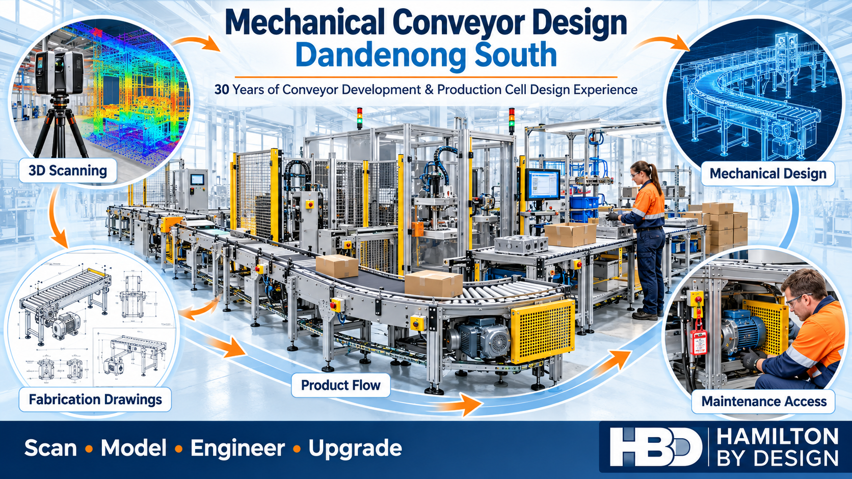
Conveyor production cell with 3D scanning, CAD modelling, fabrication drawings and maintenance access illustrations for Hamilton By Design in Dandenong South.

30 Years of Experience Developing Conveyors for Production Cells

Blue line icon of an industrial belt conveyor with rollers, support frame, gearbox and drive motor.

Hamilton By Design provides mechanical conveyor design in Dandenong South for manufacturers planning new production cells, equipment integration and conveyor upgrades. Our principal brings 30 years of experience developing and designing conveyors for production cells, supported by 3D scanning, SolidWorks modelling and fabrication drawings.

For 30 years, the principal at Hamilton By Design has worked on the development and design of conveyors for production cells. That experience shapes a practical approach to moving products between machines, workstations and process stages.

A successful conveyor design starts with understanding your production requirements. What needs to move? How quickly? In what orientation? How will operators interact with the equipment, and how will maintenance staff access it?

By combining mechanical design, 3D modelling, LiDAR scanning and engineering drawings, Hamilton By Design helps businesses develop conveyor arrangements that suit their products, processes and available factory space.

Conveyor Design That Fits Your Production Process

Conveyors connect individual machines into a working production system. Their performance depends on how well they integrate with the equipment upstream and downstream.

A conveyor may need to receive components from a machine, present products to an operator, feed a packaging station or transfer completed assemblies to the next process. Each application has different requirements for speed, spacing, loading and product handling.

Our design process considers:

  • Product dimensions, weight and orientation.
  • Required throughput and operating duty.
  • Conveyor length, width and working height.
  • Transfer points between conveyors and machines.
  • Available floor space and surrounding equipment.
  • Operator access and manual handling.
  • Cleaning, inspection and maintenance requirements.
  • Fabrication, assembly and installation constraints.

The aim is to develop a conveyor arrangement that supports the whole production cell.

New Conveyors and Existing Conveyor Modifications

Hamilton By Design can support new conveyor concepts and targeted modifications to existing systems.

Depending on the application, the mechanical design scope may include belt conveyors, roller conveyors, gravity transfers, product guides, support frames and machine interfaces.

For an existing production line, modifications might involve:

  • Extending or shortening a conveyor.
  • Changing the conveyor height or direction.
  • Connecting new machinery to an existing line.
  • Modifying product guides or transfer arrangements.
  • Replacing deteriorated frames and brackets.
  • Improving maintenance access.
  • Developing guarding and access arrangements.
  • Updating drawings to reflect the equipment installed.

Sometimes a targeted modification provides the improvement a business needs. We begin by understanding the issue and assessing the existing arrangement before developing the design scope.

Integrating Conveyors into Production Cells

Production-cell conveyor design requires attention to the interaction between people, products and machinery.

For example, installing a faster conveyor will not necessarily increase output if the next machine cannot accept products at that rate. Similarly, a compact layout may save floor space while making cleaning or maintenance difficult.

Hamilton By Design considers the proposed conveyor within the wider production process, including:

Product Flow

We assess how products enter, travel through and leave the conveyor. Product stability, spacing and transfer geometry can influence whether the arrangement operates smoothly.

Machine Interfaces

Conveyor heights, entry points and discharge positions need to coordinate with the equipment they serve. Mechanical interfaces should be established early so that brackets, guides and transition details can be developed around agreed dimensions.

Operator Interaction

Loading, unloading, inspection and assembly tasks influence conveyor positioning. The layout should account for how operators carry out their work and move through the production area.

Maintenance Access

Bearings, rollers, drives and adjustment points need suitable access. Considering component removal and maintenance tasks during design helps avoid difficult arrangements after installation.

Electrical controls, sensors and automation interfaces can be coordinated with the clientโ€™s nominated electrical or automation specialists.

3D Scanning Before Conveyor Upgrades

When a new conveyor must fit into an existing factory, reliable information about the surrounding equipment is valuable.

Older drawings may not show machinery relocations, additional services or previous modifications. Measuring only the proposed conveyor footprint can also miss obstructions above or beside it.

Hamilton By Designโ€™s 3D laser scanning services can capture visible existing conditions to support layout planning and mechanical design.

A scan can help establish:

  • Existing conveyor routes and elevations.
  • Machine positions and external geometry.
  • Columns, walls and nearby services.
  • Available space for new equipment.
  • Access routes and installation constraints.
  • Potential clashes with surrounding plant.

Capturing the factory before finalising a layout allows proposed equipment to be assessed against the existing environment.

Where close-tolerance interfaces are required, critical dimensions can be identified for separate verification. This is particularly relevant to mounting holes, shafts, bearings and machined connections.

3D Modelling for Conveyor Layouts

A coordinated 3D model makes the proposed conveyor arrangement easier to review before fabrication begins.

Hamilton By Design uses SolidWorks and CAD tools to develop mechanical assemblies and communicate the relationship between conveyors, machines, support frames and surrounding plant.

Models can support reviews of:

  • Overall conveyor geometry.
  • Product entry and discharge positions.
  • Frame and support arrangements.
  • Drive locations and component access.
  • Guarding envelopes.
  • Installation and assembly space.
  • Interfaces with existing equipment.

Production staff, maintenance personnel and fabricators can review the same arrangement and identify practical issues while changes are still straightforward to make.

For businesses in Dandenong South planning a production-cell upgrade, this provides an opportunity to resolve layout questions before committing to fabrication.

Mechanical Design and Fabrication Drawings

Once the arrangement is agreed, the design can progress into drawings and documentation appropriate to the project.

Our mechanical drafting services can support the manufacture, assembly and installation of new or modified conveyor equipment.

Depending on the agreed scope, deliverables may include:

  • General arrangement drawings.
  • Conveyor assembly drawings.
  • Frame and bracket fabrication details.
  • Sheet-metal and product-guide details.
  • Component drawings.
  • Bills of materials.
  • DXF cutting profiles.
  • STEP files for supplier coordination.
  • Installation and interface drawings.

The documentation package is established around the needs of the client, fabricator and installation team.

Designing for Maintenance and Practical Operation

A conveyor should be assessed over its working life, including the tasks needed to keep it operating.

During design, we consider questions such as:

  • Can the belt or rollers be replaced without dismantling surrounding equipment?
  • Are adjustment points accessible?
  • Can debris be removed from beneath the conveyor?
  • Is there space to inspect and maintain the drive?
  • Can guards be removed and reinstated for authorised maintenance?
  • Are wear components practical to source and replace?

These decisions affect maintenance effort, downtime and the usefulness of the final installation.

Machinery hazards and guarding requirements should also be considered during design. Conveyor safety depends on the complete arrangement, including access, controls, operating procedures and maintenance tasks.

A Practical Process from Concept to Installation Support

Hamilton By Designโ€™s mechanical engineering consulting can be tailored to a focused conveyor modification or a broader production-cell project.

1. Define the Requirement

We discuss the product, production target, existing problems, available space and project timing.

2. Establish Existing Conditions

Relevant drawings, measurements and site information are reviewed. Where useful, 3D scanning captures the surrounding plant.

3. Develop the Concept

Proposed layouts and mechanical arrangements are developed for review with the people who operate and maintain the equipment.

4. Complete the Detailed Design

The agreed concept progresses into component selection, mechanical details and the required design checks.

5. Prepare the Documentation

Models, drawings and supporting information are prepared for the agreed fabrication and installation scope.

6. Support Fabrication and Installation

Where included, we assist with technical queries and review changes that arise during manufacture or installation.

Frequently Asked Questions

Can Hamilton By Design modify an existing conveyor?

Yes. We can assess the existing arrangement and develop mechanical modifications to suit a new machine, revised product flow or changed production requirement.

Do we need a 3D scan for every conveyor project?

No. A straightforward conveyor may be designed using verified measurements and suitable drawings. Scanning is particularly useful where the factory is congested, records are incomplete or several equipment interfaces need coordination.

Can you design a conveyor around our available factory space?

Yes. Available space, equipment positions, access and maintenance requirements can be incorporated into the layout process. Providing information early helps establish the constraints before detailed design begins.

Can you provide drawings for our preferred fabricator?

Yes. The drawing package can be developed around the agreed fabrication scope and your fabricatorโ€™s requirements.

Can you assist before we purchase new machinery?

Yes. Early layout planning can help establish conveyor interfaces, working heights, access requirements and available installation space before machinery positions are finalised.

Discuss Your Conveyor Project in Dandenong South

Are you planning a new production cell, adding machinery or modifying an existing conveyor?

Hamilton By Design brings together 30 years of conveyor development and design experience, mechanical engineering, 3D scanning, CAD modelling and fabrication documentation.

Send us your existing drawings, photographs or a description of the production issue. Include the product being handled, your required throughput and any installation deadline so we can discuss a suitable scope.

Contact Hamilton By Design to discuss mechanical conveyor design in Dandenong South.


Hamilton By Design logo displayed on a blue tilted rectangle with a grey gradient background

Contact Us – Talk To Us

Name
Would you like us to arrange a phone consultation for you?
Address

Our clients:


Related Services for Conveyor and Production Cell Projects

Explore Hamilton By Design services that support conveyor design, factory upgrades and equipment integration in Dandenong South.

3D Scanning Bellevue Hill: Start with As-Built Data to Establish What Is Possible

Watercolour illustration of a Bellevue Hill home transitioning from existing conditions to a blue point cloud and proposed renovation, with a LiDAR scanner in the foreground.
Blue 3D LiDAR scanner icon on a tripod with scanning waves

Planning changes to your Bellevue Hill property starts with understanding what is already there. Before developing a new layout, replacing a staircase or designing an extension, as-built data provides the measured foundation needed to explore what is possible.

Existing drawings may show the original design, but buildings change over time. Renovations, altered openings, different floor levels and undocumented additions can leave a gap between the drawings and the property as it stands today.

3D scanning in Bellevue Hill helps close that gap. By recording accessible, visible building surfaces, laser scanning creates a three-dimensional point cloud that your project team can use to understand existing geometry and develop proposed changes.

Understand Your Property Before Designing Changes

A renovation idea might begin with a simple question:

  • Can we fit a new staircase into the existing space?
  • Could the ground floor layout work better?
  • How would an extension connect to the existing building?
  • Is there sufficient clearance for new equipment or services?
  • Will a proposed balcony, balustrade or architectural feature fit?

Answering these questions requires more than an approximate room size. Designers need to understand how walls, floors, ceilings, openings and adjoining spaces relate to one another.

An as-built scan provides that spatial context. It helps your architect, designer, engineer and builder assess options against measured existing conditions.

Establish the existing geometry first, then develop the design around it.

What Can 3D Laser Scanning Capture?

Depending on access and the agreed scope, a property scan can record:

  • Internal room geometry and wall positions.
  • Floor surfaces and changes in level.
  • Ceiling heights and visible beams.
  • Doorways, windows and other openings.
  • Existing stairs, landings and surrounding spaces.
  • External faรงades and accessible roof surfaces.
  • Balconies, terraces and courtyard geometry.
  • Visible pipework, ductwork and plant.
  • Connections between existing buildings and proposed work areas.

The scans are combined into a registered point cloud, allowing the captured spaces to be reviewed together.

This is particularly useful when a project involves several levels or alterations that must connect accurately with an existing building.

Establish What Fits Before Committing to Construction

A proposed design can look convincing on paper while overlooking a constraint in the existing property.

For example, a replacement staircase must work within the available opening and connect with the actual floor levels. Its position also affects nearby doors, circulation space and overhead clearance.

Scanning the staircase area early gives the design team a measured reference for testing the proposal. Potential conflicts can then be identified while the design is still being developed.

The same approach applies to custom joinery, glazing, steelwork and other components that must fit into an existing space. Working from measured geometry can reduce uncertainty before fabrication, with critical dimensions verified to the tolerances required for the installation.

Support Renovations and Extensions in Bellevue Hill

For homeowners planning alterations in Bellevue Hill, as-built scanning can support several stages of a project.

Early feasibility and concept design

Captured geometry helps designers compare layout options and understand the space available. It provides a practical starting point for discussing what could change and where further investigation is needed.

Detailed design and coordination

As the proposal develops, the point cloud can help the project team coordinate new work with existing walls, floors, openings and visible services.

Fabrication and installation planning

Where new components interface with the existing building, scan data can support modelling, detailing and fit checks. The capture method and verification requirements should be agreed around the intended use.

Recording completed work

A further scan can document accessible completed geometry and support comparisons with the design where this forms part of the project scope.

From Point Cloud to Useful Drawings and Models

A point cloud is the starting dataset. Its value comes from how it is used.

Some project teams can work directly with the scan data. Others need selected geometry converted into CAD drawings or a 3D model.

Hamilton By Design combines terrestrial LiDAR scanning, point cloud processing and optional CAD modelling and drafting to support design and verification workflows. Learn more about our 3D point cloud scanning services in Sydney.

For your Bellevue Hill project, the required outputs should be agreed before scanning. These may include a registered point cloud, selected as-built drawings or a model of the areas relevant to the proposed work.

Defining the deliverables early helps ensure the information is useful to the people making the design decisions.

Match the Scanning Scope to the Project

The right scanning scope depends on what you are planning.

A staircase replacement may need detailed capture of the stairwell, adjoining landings and floor connections. A larger renovation may require several rooms, external elevations and surrounding access areas.

Before capture, useful questions include:

  • What changes are being considered?
  • Which existing surfaces and connections affect the design?
  • Who will use the data?
  • What file formats do they need?
  • Which dimensions are critical?
  • Are any areas concealed or difficult to access?

These questions help determine the scan coverage, level of detail and additional checks required.

What Does a Scan Tell You About Feasibility?

3D scanning helps establish geometric feasibility: the space available, the position of visible features and how proposed work might fit.

Other aspects of feasibility require specialist assessment. A scan does not reveal concealed reinforcement, establish structural capacity or determine planning approval requirements. Those questions need input from the relevant project professionals.

Providing them with clear existing-condition data helps make their assessment better informed.

Frequently Asked Questions

Should I scan my property before renovation drawings are prepared?

Scanning early can provide a measured reference for concept design and reduce reliance on outdated drawings. The scope should be discussed with your designer so the right areas are captured.

Can scanning help with a new staircase?

Yes. It can record the accessible stairwell, floor connections and surrounding geometry to support design development. Stair design and compliance checks remain part of the appropriate design review.

Can you scan only part of a property?

Yes. A focused scope can target the rooms, faรงades or interfaces relevant to the proposed changes.

Does laser scanning see through walls?

No. Terrestrial laser scanning records surfaces visible to the scanner. Concealed spaces require access or a separate investigation method.

Can scan data be used to create CAD drawings?

Yes. Selected captured geometry can be converted into drawings or models, with the required detail and outputs agreed before work begins.

Start Your Bellevue Hill Project with Measured Existing Conditions

Before investing in detailed design, establish a clear record of your property as it stands today.

3D scanning in Bellevue Hill provides the as-built foundation for exploring layouts, checking interfaces and planning alterations with greater confidence.

Contact Hamilton By Design to discuss your property, the changes you are considering and the data your project team needs.

Capture what exists. Understand the constraints. Establish what is possible.


Hamilton By Design logo displayed on a blue tilted rectangle with a grey gradient background

Contact Us – Talk To Us

Name
Would you like us to arrange a phone consultation for you?
Address

Our clients:


Related 3D Scanning Services in Sydney

Planning alterations to your Bellevue Hill property? Explore Hamilton By Designโ€™s Sydney scanning services for capturing existing conditions, developing digital models and supporting construction planning.

3D Scanning in Point Piper: Plan Property Changes Around What Is Actually There

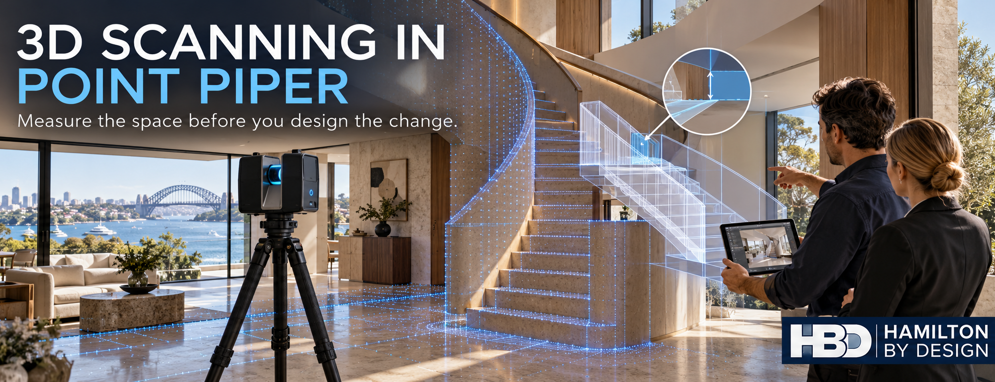
3D LiDAR scanner capturing a Point Piper homeโ€™s staircase while a proposed stair design is checked against the existing space.

โ€œYour Honour, the stairs did not fit.โ€

Blue 3D LiDAR scanner icon on a tripod with scanning waves

It sounds like a line from a dispute you would rather avoid. But a staircase, lift, custom joinery package or new opening can be designed around dimensions that looked reasonable on a drawing and still fail to fit the finished space.

If you are planning changes to a property in Point Piper, the first step is to understand its existing geometry. Hamilton By Design uses stationary 3D LiDAR scanning to capture visible walls, floors, ceilings, stairs and building services. The registered point cloud can then support measured drawings and 3D models for design and coordination. LiDAR & 3D Modelling

A property tour and a design record serve different purposes

A 3D tour can help prospective buyers explore a property online. It is a useful presentation tool, but an attractive walkthrough should not automatically become the dimensional basis for a renovation.

For design work, the questions are more specific: How much clear space is available? Are the walls square? Where does the ceiling change height? Will the proposed stair, lift or joinery fit alongside the existing structure and services?

A stationary terrestrial scanner can capture detailed geometry from planned scan positions. Mobile SLAM scanning can document spaces quickly and may be suitable for broader layout work. The accuracy and detail available from either method depend on the equipment, site conditions, capture method and processing. A published comparison found both methods useful for building documentation, while the stationary scanner provided better detail for intricate features in the study. isprs-archives.copernicus.org

Where better measurements can make a difference

For a Point Piper property, an as built scan may help an architect, builder or specialist supplier plan:

  • A replacement staircase or altered stair opening
  • A lift or access upgrade
  • Kitchen, bathroom and custom joinery work
  • Changes to ceiling heights or service routes
  • Plant room and building services upgrades
  • A refurbishment that must connect neatly to existing construction

The value is in capturing the areas that matter to the proposed change, then checking critical dimensions before anything is fabricated. A scan provides a detailed record of visible surfaces; concealed construction still needs to be investigated, and critical interfaces should be verified for their intended use.

Consider the cost of getting the starting dimensions wrong

A lower cost scan may be entirely suitable when the goal is a visual record or an approximate layout. When a component must fit an existing opening, the useful question is whether the capture and checking process meets the projectโ€™s required tolerance.

Finding a clash during design gives the team options. Finding it when a finished staircase arrives on site can mean redesign, modification and delay. The scanner alone does not guarantee a successful fit: scan planning, registration, interpretation and final dimensional checks all matter. Research on terrestrial laser scanning likewise identifies several sources of measurement error that must be considered when using scan data for dimensional work. NIST

From Point Piper property scan to practical design information

Hamilton By Design can capture the existing space and provide a registered point cloud for review. Where required, that data can be developed into CAD drawings or a 3D model for the design team, fabricator or installer. The scope should identify the proposed alteration and the dimensions that need particular attention before scanning begins. Hamilton By Design Co.

If the project requires a legal property boundary survey, engage a registered land surveyor. A building scan does not determine title boundaries; in NSW, boundary surveys are the work of registered land surveyors. Automatic Mutual Recognition (AMR)

Planning a renovation or property upgrade in Point Piper? Contact Hamilton By Design with your plans and the proposed changes. We can discuss what needs to be captured so your design team starts with a useful record of the existing property.

3D Scanning in Point Piper: Plan Property Changes Around What Is Actually There

โ€œYour Honour, the stairs did not fit.โ€

It sounds like a line from a dispute you would rather avoid. But a staircase, lift, custom joinery package or new opening can be designed around dimensions that looked reasonable on a drawing and still fail to fit the finished space.

If you are planning changes to a property in Point Piper, the first step is to understand its existing geometry. Hamilton By Design uses stationary 3D LiDAR scanning to capture visible walls, floors, ceilings, stairs and building services. The registered point cloud can then support measured drawings and 3D models for design and coordination. LiDAR & 3D Modelling

A property tour and a design record serve different purposes

A 3D tour can help prospective buyers explore a property online. It is a useful presentation tool, but an attractive walkthrough should not automatically become the dimensional basis for a renovation.

For design work, the questions are more specific: How much clear space is available? Are the walls square? Where does the ceiling change height? Will the proposed stair, lift or joinery fit alongside the existing structure and services?

A stationary terrestrial scanner can capture detailed geometry from planned scan positions. Mobile SLAM scanning can document spaces quickly and may be suitable for broader layout work. The accuracy and detail available from either method depend on the equipment, site conditions, capture method and processing. A published comparison found both methods useful for building documentation, while the stationary scanner provided better detail for intricate features in the study. isprs-archives.copernicus.org

Where better measurements can make a difference

For a Point Piper property, an as built scan may help an architect, builder or specialist supplier plan:

  • A replacement staircase or altered stair opening
  • A lift or access upgrade
  • Kitchen, bathroom and custom joinery work
  • Changes to ceiling heights or service routes
  • Plant room and building services upgrades
  • A refurbishment that must connect neatly to existing construction

The value is in capturing the areas that matter to the proposed change, then checking critical dimensions before anything is fabricated. A scan provides a detailed record of visible surfaces; concealed construction still needs to be investigated, and critical interfaces should be verified for their intended use.

Consider the cost of getting the starting dimensions wrong

A lower cost scan may be entirely suitable when the goal is a visual record or an approximate layout. When a component must fit an existing opening, the useful question is whether the capture and checking process meets the projectโ€™s required tolerance.

Finding a clash during design gives the team options. Finding it when a finished staircase arrives on site can mean redesign, modification and delay. The scanner alone does not guarantee a successful fit: scan planning, registration, interpretation and final dimensional checks all matter. Research on terrestrial laser scanning likewise identifies several sources of measurement error that must be considered when using scan data for dimensional work. NIST

From Point Piper property scan to practical design information

Hamilton By Design can capture the existing space and provide a registered point cloud for review. Where required, that data can be developed into CAD drawings or a 3D model for the design team, fabricator or installer. The scope should identify the proposed alteration and the dimensions that need particular attention before scanning begins. Hamilton By Design Co.

If the project requires a legal property boundary survey, engage a registered land surveyor. A building scan does not determine title boundaries; in NSW, boundary surveys are the work of registered land surveyors. Automatic Mutual Recognition (AMR)

Planning a renovation or property upgrade in Point Piper? Contact Hamilton By Design with your plans and the proposed changes. We can discuss what needs to be captured so your design team starts with a useful record of the existing property.


Hamilton By Design logo displayed on a blue tilted rectangle with a grey gradient background

Contact Us – Talk To Us

Name
Would you like us to arrange a phone consultation for you?
Address

Our clients:


3D LiDAR Scanning Dandenong South for Plant Layouts and Machinery Upgrades

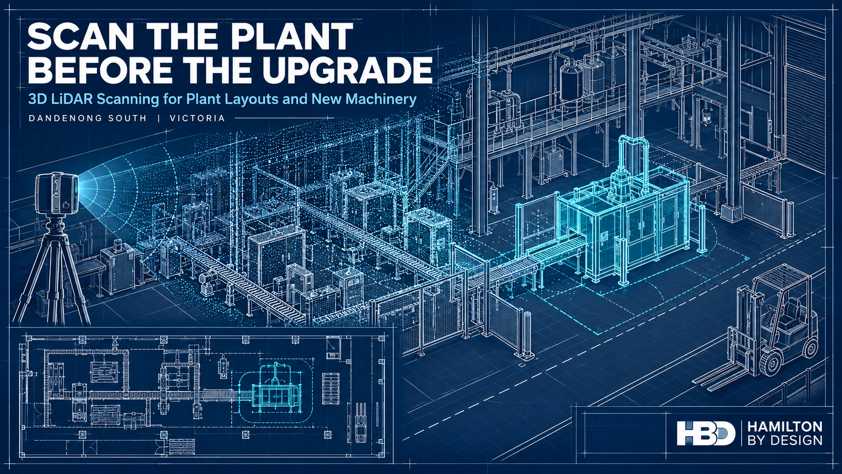
Technical drawing of a factory being scanned with LiDAR, showing a point cloud and proposed machinery in the plant layout.
Blue 3D LiDAR scanner icon on a tripod with scanning waves

A machinery upgrade often begins with an equipment specification and a proposed position on a floor plan. The machine may fit within the room on paper, but the drawing may not show a relocated conveyor, a low pipe, an altered platform or the space needed to remove a motor for maintenance.

These details are much easier to address before equipment is ordered and fabrication begins.

Hamilton By Design provides 3D LiDAR scanning in Dandenong South to help manufacturers and project teams understand their existing plant before planning a change. We can capture factory layouts, machinery, conveyors, pipework and surrounding structures, then develop the point clouds, CAD models and drawings needed to assess an upgrade.

The value of scanning early is that the project starts with a reliable picture of the space it must work within. The scan does not decide where a machine should go. It gives the people making that decision better information.

Start with the Plant as It Exists Today

Factories change continuously. A machine is moved to improve production. A pipe is rerouted during maintenance. A guard is replaced, a platform is extended or temporary equipment becomes permanent. Each change may be understood by the people who made it, but it may never reach the master layout.

By the time a larger upgrade is proposed, the available drawings can be several changes behind the physical plant.

A 3D LiDAR survey records visible surfaces throughout the relevant area. The resulting point cloud provides a measurable spatial record of machinery, building elements and services at the time of the survey. HBD can use it to prepare an updated layout or model selected parts of the plant for design work.

This is useful whether the project concerns one machine or an entire production area. The survey scope can concentrate on the spaces and interfaces that affect the decision, rather than treating every object in the factory as equally important. HBDโ€™s broader 3D laser scanning services in Melbourne support this type of existing-condition work.

Plan the Layout Before Committing to Equipment

A new machine needs more than a space large enough for its footprint. The project team also needs to consider how materials reach it, how finished product leaves it, how operators use it and how maintenance staff access it.

Early plant layout scanning can help answer questions such as:

  • Will the equipment fit alongside the machinery already installed?
  • Is there room for feeding, discharge and product transfer?
  • Can guards and access doors open as intended?
  • Can a motor, gearbox or other serviceable component be removed later?
  • Do existing columns, platforms, pipework or cable routes affect installation?
  • Will the change interrupt a pedestrian route, forklift movement or emergency access?

These questions are difficult to resolve confidently from an old two-dimensional plan. A point cloud allows the proposed equipment to be reviewed in relation to the visible conditions around it.

For a Dandenong South manufacturer considering a new production line, packing machine or conveyor, scanning at the concept stage can inform the equipment brief itself. It may reveal that a different orientation, connection point or maintenance arrangement would be more practical. Finding that out before purchase gives the client more room to make an informed choice.

Compare Upgrade Options Against the Same Site Data

Plant upgrades rarely have only one possible arrangement. A business may be deciding whether to extend a line, replace a machine in its current position or move part of the process to another area.

An as-built survey provides a consistent reference for comparing those options. HBD can develop an appropriate plant layout from the scan data and use it with the clientโ€™s equipment information to examine space, access and likely physical clashes. The level of CAD modelling should match the decision: an early layout study may need less detail than a fabrication package.

This staged approach makes the information easier to use. A maintenance manager may first need to know whether a proposed arrangement is practical. Once an option is selected, the project may need more detailed checks of mounting points, conveyor interfaces or nearby services.

HBDโ€™s mechanical engineering support in Melbourne can connect the survey to mechanical design and documentation as the project develops.

Reduce Uncertainty Before a Shutdown

A short installation window leaves little time to correct a component that does not fit. If the first accurate check of an interface happens during the shutdown, a small discrepancy can delay several trades at once.

Early scanning can help a project team examine where a new item meets the existing plant. That might include the position of a conveyor, the envelope around a pump skid or the space available for a fabricated support. A model can also help the fabricator understand nearby obstructions and the likely installation sequence.

The important distinction is between surveying a space and verifying a critical fit. LiDAR is well suited to recording larger plant areas and visible geometry. Tight tolerances, concealed connections and important machined features may require separate measurement. HBD can identify those checks as part of a defined scope, so the drawings make clear which dimensions have been verified.

Our 3D scanning for fabrication service in Melbourne applies this information to design review, fit-up and installation planning.

See How the New Machinery Affects the Whole Area

A plant layout is a working system, not simply a collection of machine outlines. Moving one piece of equipment can alter the way people, materials and maintenance activities move through the area.

A new conveyor might improve product flow but narrow access to another machine. A larger enclosure might fit beside a wall but leave insufficient space to open its service panels. A relocated packing station might change the route between production and dispatch.

Reviewing these relationships early can improve the design brief. The scan gives the project team a shared view of the physical constraints, while the people who operate and maintain the plant explain how the space is actually used. Both forms of information are needed.

This is particularly relevant where factory production and warehouse operations meet. A survey can record doors, columns, dock areas and fixed equipment, but forklift and pedestrian arrangements also require a site-specific traffic-management review. WorkSafe Victoria advises separating forklifts from pedestrians as a way to reduce risk.

Use the Survey for Guarding and Maintenance Access

Machinery changes can create new safety questions. Once equipment is placed in its proposed position, will a guard fit around it? Can workers clean and maintain the machine without reaching through a danger area? Is there suitable space for a platform or walkway?

LiDAR scanning can record the physical arrangement needed to explore these questions. HBD can use the survey when developing guard concepts, access layouts and fabrication drawings through its machine guarding design service.

The geometry is only one part of the assessment. Guarding decisions also depend on the machineโ€™s hazards and the tasks performed by operators and maintenance staff. Relevant parts of the AS/NZS 4024 machinery-safety series may apply, while fixed platforms, walkways, stairs and ladders may require assessment against AS 1657. WorkSafe Victoriaโ€™s Compliance code: Plant provides guidance for managing plant-related risks in Victorian workplaces.

Considering these matters during layout planning is more effective than discovering, after a machine has been positioned, that its guard or maintenance access has nowhere to go.

Make Better Use of Existing Machinery Data

Some upgrades begin with reliable supplier models for the proposed equipment but little trustworthy information about the equipment already on site. Others involve older machines for which no usable CAD model exists.

HBD can use site scanning alongside available OEM information to build a model suited to the project. It may be enough to represent an existing machineโ€™s overall envelope and connection points. Where a replacement component or modified interface is required, more detailed reverse engineering and 3D scanning may be appropriate.

The aim is to model what the project needs to know. An early plant layout does not need every fastener represented. A replacement housing, by contrast, may require close attention to its measured features, function and intended fit.

Turn the Scan into Useful Project Deliverables

A point cloud is a valuable record, but different members of a project team need different information from it. The equipment supplier may need installation clearances. The client may need an updated 2D floor plan. A fabricator may need controlled drawings. The maintenance team may want a record that can support later changes.

Depending on the agreed scope, HBD can provide registered scan data, plant layouts, 3D CAD models, general arrangement drawings and selected fabrication details. Our mechanical drafting services can carry the work beyond the initial survey when drawings are required for review or manufacture.

It is worth defining the deliverables before scanning starts. That allows the survey to capture the necessary areas and helps identify where extra inspection or critical-dimension checks will be needed. It also makes the limits of the data clear to everyone using it.

The agreed file formats, access arrangements and retention period can be set out with the project scope, particularly where the scan includes commercially sensitive production equipment.

Why the Timing Matters

Scanning after a layout is finalised can still be useful for checking and documentation. Scanning before major decisions are locked in gives the project more opportunities to benefit from the information.

At that stage, the client may still be able to change a machineโ€™s orientation, ask an equipment supplier to modify an interface or select a different location. The project team can resolve spatial questions before drawings are issued for fabrication. It can also identify information that the scan cannot establish, such as hidden services, floor capacity or a componentโ€™s material, and arrange the appropriate specialist checks.

For a working factory, early scanning is a way to make the design process more deliberate. It does not remove every uncertainty, but it shows many of the physical constraints while there is still time to respond to them.

Frequently Asked Questions

When should we scan a plant for a machinery upgrade?

Ideally, scan while the project team is still considering layouts or preparing the equipment brief. The survey can then inform the arrangement before the machinery position and interfaces are fixed. A further targeted check may be appropriate before fabrication or installation.

Do we need to scan the entire factory?

Usually, the survey can be scoped to the area affected by the change. It should include enough surrounding plant, access space and services to assess the proposed machinery and its connections. A wider scan may be worthwhile if several future upgrades are being planned.

Can HBD prepare a 2D plant layout from the scan?

Yes. The agreed deliverables can include a 2D layout, registered point cloud and selected 3D CAD models. The level of detail should reflect whether the plan is intended for early options, engineering design or fabrication.

Can a proposed machine be placed into the existing plant model?

Yes, provided suitable dimensions or a supplier model are available. Reviewing the proposed equipment against surveyed conditions can help identify spatial conflicts and questions that need further checking.

Will LiDAR scanning confirm that the floor can carry a new machine?

No. Scanning records visible geometry; it does not establish the capacity of a slab or its foundations. Loading and structural capacity require appropriate records, investigation and assessment by a suitably qualified practitioner.

Can scanning be done while production continues?

Often, but the method depends on site access, moving machinery, visibility and the areas that must be captured. Some measurements may be better completed during a production pause or shutdown. HBD can plan the survey with the site team around the projectโ€™s requirements.

What information should we send HBD first?

A marked-up floor plan or photographs are a useful start. Explain what machinery you want to add or change, what decision you need to make, any proposed installation date and what drawings or supplier models you already have. That information helps define the survey area and the most useful deliverables.

Plan the Upgrade from a Measured Starting Point

If you are planning to add machinery, rearrange a production area or upgrade equipment in Dandenong South, an early plant layout survey can give your team a clearer starting point. Hamilton By Design can discuss the proposed change, capture the existing conditions and develop the scan data, models and drawings needed for the next decision.

Contact Hamilton By Design to discuss 3D LiDAR scanning for your Dandenong South plant layout or machinery upgrade.


Hamilton By Design logo displayed on a blue tilted rectangle with a grey gradient background

Contact Us – Talk To Us

Name
Would you like us to arrange a phone consultation for you?
Address

Our clients:


Machinery Reverse Engineering in Brendale: Turning Existing Equipment into Usable Engineering Information

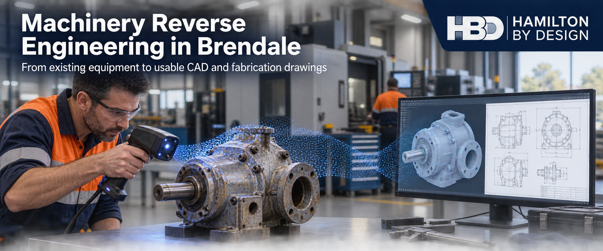
HBD engineer scanning a worn machinery component in a Brendale workshop, with a CAD model and fabrication drawing displayed beside it.
Blue 3D LiDAR scanner icon on a tripod with scanning waves

In a Brendale workshop, an old machine can still be central to production even when its original drawings have disappeared. A replacement component might be available only after a long lead time. The machine may have been repaired or modified several times, so an original manual no longer describes what is installed. When a part fails, the immediate question is practical: how can the team make a reliable replacement without creating another problem at assembly or start-up?

Brendale is well placed to make parts. Its industrial precinct brings together machining, fabrication, product development, engineering and distribution. The City of Moreton Bay identifies it as a leading advanced manufacturing location with access to the Bruce Highway and wider supply chains. The challenge for an individual business is often getting from a physical machine to the right engineering information for those capable local workshops to use.

Hamilton By Design (HBD) helps bridge that gap through machinery surveys, component scanning, reverse engineering, mechanical design and fabrication documentation. The aim is to capture what is actually there, understand what the component must do, and produce information that can be reviewed, manufactured and retained for future work.

A local manufacturing precinct with a practical advantage

Brendale is more than an address on the northern side of Brisbane. The City of Moreton Bay describes Brendale as a major advanced manufacturing precinct. Local operations include precision machining, pressing and tooling, engineered products, fabrication, equipment maintenance and product development. Some businesses make their own products; others manufacture or repair equipment used well beyond South East Queensland.

The range is visible in the precinct itself. Berg Engineeringโ€™s Brendale workshop describes large-capacity machining alongside fabrication, welding and pump and valve work. ARROWES describes an in-house team developing and manufacturing roadwork safety products for markets across Australia and New Zealand. These are examples of the local industrial mix, not claims that either business uses HBDโ€™s services.

That mix creates an opportunity for maintenance and production teams. A workshop capable of making a part may be nearby, but the workshop still needs sound geometry, material requirements, critical fits and a clear drawing. A fitterโ€™s sketch can be valuable, yet it may not show how a worn surface originally fitted its mating part. Similarly, a factory floor plan may show a proposed machine position without recording the pipework, access routes or equipment already in the way.

The strongest use of machinery reverse engineering in Brendale is therefore to connect local manufacturing capability with a dependable record of the existing asset. HBDโ€™s scan-to-CAD reverse engineering process can turn suitable physical measurements into component models and fabrication information. The extent of scanning and engineering depends on the job: a small bracket, a worn pump component and a complete production cell need different methods.

When an obsolete part needs more than a copy

Reverse engineering begins with the purpose of the part. What does it locate, carry, seal, guide or protect? What connects to it? Has a bearing, shaft, gearbox or drive been changed since the machine was built? Those questions matter because the existing component may be damaged or worn. Copying every surface can preserve the very defect that caused the maintenance problem.

For a replacement component, HBD can inspect the available part and its installed interfaces, take direct measurements where needed, capture suitable surfaces with 3D scanning and develop an editable CAD model. A drawing package may then define geometry, critical dimensions, material, fits, finishes and revision information for the manufacturer. Where the operating loads or failure consequences call for it, the design also needs an appropriate engineering assessment.

This distinction is important. A scan records visible shape within the limits of the chosen equipment and site access. It does not, by itself, establish the original design intent, internal condition, material grade or correct machining tolerance. For close-fitting features, the team should agree which dimensions require direct measurement, inspection or another metrology method before release for manufacture.

HBDโ€™s SolidWorks modelling services for Brisbane projects can support the next step: making the model useful for assemblies, alternative designs, workshop drawings and later revisions. Retaining the source scans alongside the final model helps explain what was measured and what was inferred.

Scanning the factory before moving the machine

Brendaleโ€™s manufacturing businesses also change their facilities as orders, products and equipment change. A new press, machining centre or packaging line might fit on a two-dimensional floor plan but leave too little room for a tool change, forklift movement or safe maintenance. A machine moved a short distance can affect ducting, cable trays, guarding, access and material flow.

For a small or medium factory, a targeted survey can be more useful than trying to model everything. HBD can identify the area that matters, capture the floor, major equipment, columns and relevant services, and prepare a point cloud or existing-condition model. Proposed equipment footprints can then be tested against the site record. The resulting layout can show practical clearances, likely clashes and interfaces requiring further measurement.

The broader Brisbane reality capture service explains how site data can feed mechanical drafting and plant modifications. For Brendale clients, the deliverable should be chosen at the start: a point cloud for a design team, a dimensioned equipment layout, an editable CAD model, or a more detailed installation package. A building scan alone does not automatically provide all four.

Guarding and access after a modification

An equipment change can create a new safety problem even when the original machine was properly guarded. A replacement drive may bring moving parts closer to a walkway. A new product path can require an opening in a guard. A relocated machine may leave an awkward maintenance position or restrict access to an isolation point.

HBD can use site measurements and scan data to develop guarding concepts, mounting details and fabrication drawings around the actual machine. Its machine guarding service considers operation, cleaning, maintenance and installation as well as the physical barrier. A useful design record identifies the hazard, proposed control, access needs, assumptions and review outcome.

The relevant parts of the AS/NZS 4024 safety of machinery series and Queenslandโ€™s Managing risks of plant in the workplace Code of Practice provide a framework for risk assessment and risk reduction. Where a project includes fixed platforms, walkways, stairs or ladders, AS 1657 may also apply. The exact requirements must be selected for the machine and task; a generic guard detail cannot resolve every operating risk.

Drawings that a workshop can use again

Good drafting is part of asset management. A drawing that shows a partโ€™s shape but omits its material, interfaces or revision may be difficult to use on the next shutdown. The same applies when a modified machine is shown on an old general arrangement but its new guarding, mounting points and service connections are kept only in someoneโ€™s memory.

HBDโ€™s mechanical drafting services can develop general arrangements, assembly drawings, component details, fabrication drawings and updated layouts from scans, measurements, existing drawings and site markups. Depending on the scope, a package might include a bill of materials, installation notes and a record of the as-built arrangement. Drawings can follow the applicable AS 1100 technical drawing series, together with project-specific dimensional, material and fabrication requirements.

The retained information can be particularly valuable for a smaller manufacturer without a dedicated drawing office. Machinery scans, component models, factory point clouds, guarding records, materials and revisions create a starting point for the next repair or modification. They also help a new employee or external fabricator understand which version represents the current machine.

A sensible sequence for a Brendale project

The first conversation should focus on the decision the client needs to make. Is production waiting for a replacement part? Is a machine move being priced? Has a guarding audit identified a specific hazard? The answer determines what to measure and how much documentation is useful.

A practical workflow is to inspect the equipment and available records, agree the critical interfaces, capture the relevant geometry, confirm uncertain dimensions, develop the CAD model or layout, review the design and issue controlled drawings. For a production change, it may also be useful to check how the proposed arrangement affects maintenance access, material handling and installation sequence before fabrication begins.

HBD can provide the scanning, modelling and drafting inputs and define the engineering assessment needed for the agreed scope. In Queensland, professional engineering services must be performed by an appropriately registered RPEQ, under direct RPEQ supervision, or only to a prescriptive standard where that exception applies. Registration and review arrangements should be established for any work requiring professional engineering judgement or certification.

The result should be proportionate to the problem. A single replacement part may need a measured model and machining drawing. A machinery relocation may need a factory point cloud, equipment layouts and several coordinated drawing revisions. The common thread is a usable record of what exists and what is proposed.

Frequently asked questions

Can HBD reverse engineer a component if we have no original drawing?

Yes, where the component and its interfaces can be inspected and enough information is available to define its function. HBD can capture geometry and develop a CAD model and drawing. Material, tolerances, loads and critical fits still need to be established for the particular application; they should not be guessed from the scan.

Is 3D scanning in Brendale suitable for both a small part and a whole factory?

Both can be surveyed, but they need different capture methods and levels of detail. A factory point cloud is useful for equipment layouts and surrounding conditions. A close-fitting component may require a suitable part scanner plus direct dimensional checks. HBD would select the approach around the required deliverable.

Can a factory scan help us move a production machine?

It can provide an existing-condition reference for columns, equipment and visible services. The proposed position can then be checked for fit, access and likely clashes. Confirmed dimensions, service requirements and operating clearances should be added to the layout before installation decisions are finalised.

Can you prepare drawings for a local Brendale fabricator or machinist?

HBD can prepare CAD models and workshop or fabrication drawings suited to the agreed component or assembly. Before manufacture, the client and manufacturer should confirm the drawing revision, material, tolerances, finish and any required engineering approval.

Can reverse engineering also improve machine safety?

It can support a safer modification by documenting the actual machine and its interfaces. Guarding still requires a task-specific risk assessment and design review. A scan is a useful input to that work, not a safety approval on its own.

Discuss a Brendale machinery or factory project

If an obsolete part, undocumented machine or changing factory layout is holding up a decision, send HBD photographs, any available drawings, the equipment location and a short description of the problem. We can discuss the capture method, the required CAD or drawing deliverable, and the appropriate engineering review before work begins. Contact Hamilton By Design to arrange a conversation about your Brendale project.


Hamilton By Design logo displayed on a blue tilted rectangle with a grey gradient background

Contact Us – Talk To Us

Name
Would you like us to arrange a phone consultation for you?
Address

Our clients: