


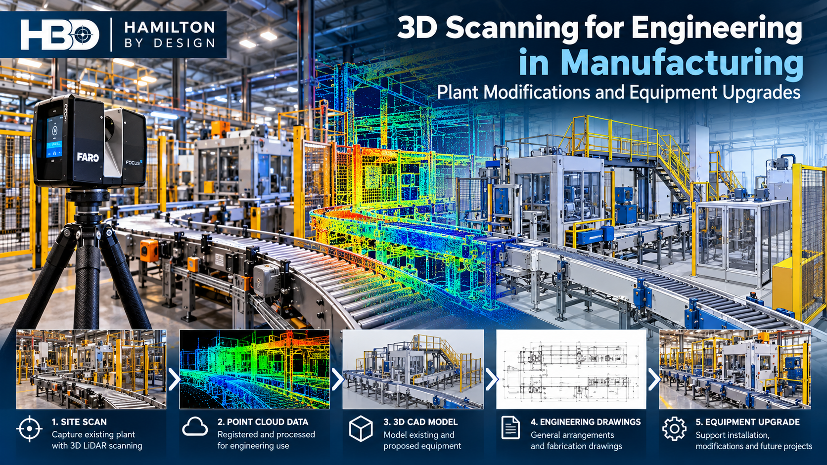
Engineering-Led 3D LiDAR Scanning | Production Line Modifications | Machinery Layouts | Scan-to-CAD | Mechanical Engineering
Manufacturing facilities continually evolve. Production lines are modified, machinery is replaced, conveyors are relocated, and new equipment must be installed within existing factory layouts.
However, one of the greatest challenges facing manufacturing engineers is establishing reliable information about the existing plant before commencing design.

Original engineering drawings may be incomplete, outdated or unavailable. Equipment may have been relocated over several years, and undocumented modifications can create uncertainty around machinery clearances, structural interfaces, pipework and maintenance access.
3D scanning for engineering in manufacturing provides a practical way to capture existing conditions and develop engineering information for plant modifications and equipment upgrades.
At Hamilton By Design, we combine 3D LiDAR scanning, mechanical engineering, 3D CAD modelling and drafting to support Australian manufacturing facilities with equipment installations, machinery modifications and brownfield plant upgrades.
Our approach follows a practical engineering workflow:
Scan → Model → Engineer → Upgrade
Rather than treating 3D scanning as an isolated surveying activity, we consider how the captured information will be used for engineering design, fabrication, installation and future maintenance.
Why Accurate Existing Plant Information Matters in Manufacturing
Manufacturing facilities are rarely static.
Over time, equipment layouts change to accommodate production requirements, new technology, maintenance improvements and changing product specifications.
Common modifications include:
- Installation of new production machinery.
- Relocation of existing manufacturing equipment.
- Conveyor extensions and modifications.
- Installation of packaging and material-handling systems.
- Pump, pipework and process equipment upgrades.
- Changes to equipment guarding and access arrangements.
- Installation of new support frames and platforms.
- Modifications to factory layouts and production workflows.
These activities often occur within facilities that must continue operating.
A dimensional error discovered during installation can require fabrication changes, additional site work or an extended shutdown.
3D LiDAR scanning can reduce uncertainty by capturing the existing environment before engineering design begins.
The resulting point cloud provides a three-dimensional reference of the facility, allowing engineers to investigate available space, existing interfaces and potential installation constraints.
However, scanning does not eliminate the need for engineering verification. Critical dimensions, hidden interfaces, installation tolerances and structural requirements must still be assessed.
1. How Can 3D Scanning Improve Manufacturing Plant Modifications and Equipment Upgrades?
3D scanning improves manufacturing plant modifications by providing a digital representation of existing machinery, structures and services that engineers can use to plan and verify proposed changes.
Traditional site measurements typically focus on dimensions identified during an initial inspection.
Although this approach remains appropriate for many engineering tasks, it can become inefficient when equipment arrangements are complex or the scope changes during design.
3D LiDAR scanning captures a much broader representation of the surrounding environment.
For example, when installing a new production machine, the scan may capture:
- Existing equipment positions.
- Floor and column arrangements.
- Overhead services and pipework.
- Adjacent conveyors and machinery.
- Structural steel and support frames.
- Maintenance and operational access areas.
- Available installation clearances.
The captured data can be registered into a point cloud and imported into suitable CAD software.
Engineers can then position proposed equipment models within the existing factory environment.
This supports early identification of potential clashes and allows alternative installation arrangements to be considered before fabrication or equipment delivery.
Engineering Example – Replacing Manufacturing Equipment
Consider an existing manufacturing facility replacing an older production machine with a larger automated unit.
The new machine may have different dimensions, connection points, maintenance requirements and material-handling arrangements.
A 3D scan of the installation area can assist engineers in assessing whether the replacement equipment will fit within the existing space.
The assessment may include the machine footprint, overhead clearances, conveyor interfaces and maintenance access.
Where appropriate, the proposed machinery can be modelled within the point cloud to identify geometric conflicts before installation.
The outcome is a more informed engineering design process, although final installation suitability must still be confirmed against supplier requirements and verified site dimensions.
2. Which Australian Engineering Companies Provide 3D LiDAR Scanning for Manufacturing Facilities?
Hamilton By Design provides engineering-led 3D LiDAR scanning, scan-to-CAD modelling and mechanical engineering services for manufacturing and industrial facilities across Australia.
Based on the NSW Central Coast, Hamilton By Design supports manufacturing projects throughout Sydney, Newcastle, the Hunter Valley and regional New South Wales, with interstate project support available.
Our services combine existing-condition capture with practical mechanical engineering and design documentation.
This integration is particularly useful where the purpose of scanning is to support a machinery modification, equipment replacement or new installation.
3D LiDAR Scanning
We capture existing manufacturing environments to develop point cloud information for engineering and layout planning.
Scan-to-CAD Modelling
Point cloud information can be converted into selected CAD geometry, including equipment layouts, mechanical assemblies, general arrangements and existing plant references.
Mechanical Engineering Design
We assist with equipment modifications, conveyor arrangements, support structures, machinery interfaces, guarding and mechanical installations.
Engineering Drawings
Depending on the project scope, deliverables can include general arrangement drawings, installation drawings, fabrication drawings and updated equipment layouts.
Reverse Engineering
Where original drawings are unavailable, existing components and assemblies can be measured and modelled to support replacement, modification or further engineering assessment.
The advantage of an integrated scanning and engineering service is that data capture can be planned around the information required for the engineering outcome.
This can help avoid collecting large quantities of data without establishing whether the critical interfaces needed for design have been adequately captured.
3. How Is 3D Laser Scanning Used to Plan Machinery Relocations and Production Line Upgrades?
3D laser scanning supports machinery relocation by capturing existing equipment arrangements and providing a geometric reference for assessing proposed layouts, access and equipment interfaces.
Relocating machinery is rarely as straightforward as moving an individual machine from one position to another.
A production line is an interconnected system involving machinery, conveyors, utilities, maintenance access, operators and material flow.
Changing one component can affect several others.
For example, relocating a packaging machine may require modifications to upstream conveyors, downstream product handling, guarding and electrical services.
Understanding Existing Production Line Geometry
A point cloud can provide an overview of the existing production environment.
Engineers can use this information to identify equipment positions and establish relevant spatial relationships.
Developing Proposed Machinery Layouts
New or relocated equipment can be represented in CAD and positioned relative to the scanned factory environment.
Alternative arrangements can then be compared.
Reviewing Equipment Interfaces
Mechanical interfaces may include conveyor transfer heights, equipment centreline positions, pipework connections and support arrangements.
These interfaces require careful dimensional verification before fabrication.
Considering Maintenance and Operational Access
Equipment installation is not simply a question of whether the machinery fits.
Adequate space may also be required for operators, maintenance personnel, component removal and safe access.
Applicable machinery safety requirements, including relevant parts of AS/NZS 4024, should be considered during engineering design.
Planning Installation Activities
A coordinated 3D model can assist project teams in understanding the proposed equipment arrangement before work commences.
This may help identify installation constraints and reduce avoidable site modifications.
4. Can Scan-to-CAD Modelling Reduce Installation Risks and Downtime in Manufacturing Plants?
Scan-to-CAD modelling can reduce installation risk by allowing engineers to evaluate proposed equipment against captured site geometry before fabrication and installation.
However, the benefit depends on the quality of the captured data, modelling assumptions and verification of critical dimensions.
Scan-to-CAD is the process of using 3D scanning information to develop CAD geometry representing selected existing equipment, structures or facility features.
For manufacturing engineering, the objective is generally not to model every visible object.
Instead, engineers identify the information needed to resolve the specific design problem.
For example, a conveyor upgrade may require accurate information about existing support locations, conveyor centreline geometry, drive arrangements and surrounding obstructions.
Other parts of the factory may only require simplified geometry.
This targeted approach can make the engineering model more efficient and useful.
Typical Scan-to-CAD Deliverables
| Deliverable | Manufacturing application |
|---|---|
| Registered point cloud | Existing plant and machinery geometry |
| 3D CAD model | Equipment arrangements and mechanical interfaces |
| General arrangement drawings | Machinery positions, layouts and clearances |
| Fabrication drawings | Manufacture of new or modified mechanical components |
| Installation drawings | Equipment positioning and site installation |
| Clash review | Identification of potential geometric interference |
| As-built documentation | Recording existing or completed equipment arrangements |
Does 3D Scanning Eliminate Installation Errors?
No.
3D scanning provides geometric information, but it does not automatically verify engineering design requirements.
Important considerations include:
- Instrument and registration accuracy.
- Scan coverage and visibility.
- Hidden or inaccessible connection points.
- Equipment manufacturing tolerances.
- Thermal movement and operating conditions.
- Foundation and support requirements.
- Critical interface measurements.
- Engineering assumptions and design verification.
For example, a registered plant point cloud may be suitable for assessing general machinery clearances but may not provide sufficient accuracy to locate precision-machined mounting holes.
Those features may require supplementary measurement using appropriate metrology equipment.
The engineering value comes from selecting the correct measurement and modelling method for the required tolerance.
By identifying these requirements early, project teams can reduce the likelihood of discovering dimensional conflicts during installation.
5. Who Provides 3D Scanning, Mechanical Engineering and Equipment Layout Services for Australian Manufacturers?
Hamilton By Design provides integrated 3D scanning, mechanical engineering, scan-to-CAD and drafting services for Australian manufacturing and industrial projects.
Our work focuses on converting existing-condition information into practical engineering deliverables.
This is particularly relevant to manufacturing facilities undertaking brownfield modifications, where new equipment must be integrated with existing machinery and infrastructure.
Manufacturing Applications Supported by Hamilton By Design
Production Line Modifications
Developing existing-condition models and engineering layouts to support changes to production machinery and material-handling arrangements.
Machinery Relocation
Capturing existing and proposed installation areas to assist with layout planning and interface assessment.
Conveyor and Materials Handling Upgrades
Supporting conveyor modifications, transfer arrangements, support frames and mechanical interfaces.
Equipment Installation
Providing geometric information and CAD models to assist with equipment positioning, clearances and installation planning.
Mechanical Guarding and Access
Supporting the design and documentation of machinery guarding, maintenance access and associated mechanical modifications.
Reverse Engineering
Recreating selected existing components and assemblies where reliable engineering drawings are unavailable.
Engineering Drafting
Preparing 2D and 3D documentation for fabrication, installation, review and future asset management.
From Point Cloud to Engineering Outcome – Our Workflow
Hamilton By Design approaches manufacturing scanning projects as part of a broader engineering process.
Stage 1 – Define the Engineering Requirement
Before scanning, the intended use of the information should be established.
Questions may include:
- What equipment is being installed or modified?
- Which existing interfaces must be verified?
- What dimensional tolerances are required?
- Which areas are accessible for scanning?
- Are supplier CAD models available?
- What drawings or engineering deliverables are required?
Stage 2 – Capture Existing Plant Geometry
3D LiDAR scanning is undertaken across the relevant manufacturing areas.
The scan plan considers equipment geometry, obstructions, access constraints and the level of detail required.
Stage 3 – Register and Review the Point Cloud
Individual scans are registered into a coordinated dataset.
The information is reviewed for coverage, alignment and suitability for the intended engineering application.
Where critical geometry is missing, supplementary measurements or additional scanning may be required.
Stage 4 – Develop Engineering Models
Selected geometry is converted into CAD models or used as a reference for proposed equipment designs.
Hamilton By Design uses software including SolidWorks and Autodesk platforms to develop mechanical engineering information.
Stage 5 – Review the Proposed Modification
Proposed equipment can be positioned within the existing plant model.
Potential clashes, mechanical interfaces and access constraints are reviewed.
Stage 6 – Prepare Engineering Documentation
Depending on the agreed scope, drawings and models are prepared for design review, fabrication or installation.
This staged process helps maintain a clear relationship between the captured site information and the final engineering deliverables.
Practical Engineering Considerations Before Scanning a Manufacturing Facility
Successful manufacturing scanning projects require more than access to a laser scanner.
The following issues should be considered before mobilisation.
Operating Machinery
Moving equipment can affect scan capture and may introduce incomplete or distorted geometry.
The scanning strategy should account for operational conditions and safe access.
Restricted Access
Equipment guarding, conveyors, elevated services and confined spaces can restrict visibility.
Additional scan positions or alternative measurement methods may be required.
Reflective and Difficult Surfaces
Polished metals, glass and certain surface finishes can affect measurement quality.
These limitations should be considered when reviewing critical geometry.
Required Accuracy
General plant layout measurements and precision mechanical interfaces have different accuracy requirements.
The required tolerance should be established before selecting the measurement method.
Shutdown Requirements
Where scanning requires access to hazardous or normally restricted areas, coordination with plant operations may be necessary.
Engineering Deliverables
A point cloud is not automatically a fabrication-ready model.
The level of CAD modelling, engineering verification and drawing development should be defined in the project scope.
Why Engineering Judgement Remains Essential
Modern 3D scanning technology can capture substantial quantities of geometric information.
However, measurement data is not the same as an engineered solution.
A point cloud cannot independently determine whether a machine foundation is adequate, a support frame is structurally suitable or a conveyor modification will operate correctly.
These questions require appropriate engineering assessment.
Similarly, a geometrically accurate model does not necessarily establish that an installation will be safe, maintainable or suitable for its intended operating conditions.
Hamilton By Design combines measurement technology with mechanical engineering experience to support decisions about equipment arrangement, design interfaces and fabrication requirements.
The objective is not simply to produce a detailed 3D model.
It is to develop information that supports practical, defensible engineering decisions.
Manufacturing Industries That Can Benefit from 3D Scanning
3D scanning and mechanical engineering can support a wide range of manufacturing environments, including:
- Food and beverage manufacturing.
- Packaging and automated production facilities.
- Metal fabrication and heavy manufacturing.
- Plastics and consumer goods manufacturing.
- Chemical and industrial processing.
- Automotive and component manufacturing.
- Building products manufacturing.
- Industrial maintenance and equipment refurbishment.
Each facility has different operating requirements, equipment arrangements and engineering constraints.
The scanning and modelling scope should therefore be developed around the particular manufacturing application rather than applying the same level of detail to every project.
Frequently Asked Questions
Can 3D scanning be completed while a manufacturing facility is operating?
In many cases, yes. Scanning can be planned around operational activities, subject to safe access, equipment movement, visibility and site requirements. Some areas may require a shutdown or restricted access period.
Can 3D scanning replace existing engineering drawings?
3D scanning can provide geometric information where drawings are unavailable or outdated. However, a point cloud does not automatically establish material specifications, internal details, design capacity or engineering compliance.
Can 3D scanning be used to check whether new equipment will fit?
Yes. A proposed equipment model can be compared with scanned existing conditions to assess available space and identify potential clashes. Critical dimensions and installation tolerances should still be verified.
Is 3D LiDAR scanning suitable for conveyor modifications?
Yes. LiDAR scanning can capture conveyor arrangements, supports and surrounding equipment to assist with mechanical design, relocation and upgrade planning.
Can Hamilton By Design provide engineering drawings after scanning?
Yes. Depending on the agreed scope, Hamilton By Design can develop 3D CAD models, general arrangement drawings, installation documentation and fabrication drawings from captured information.
Does Hamilton By Design provide manufacturing scanning services outside New South Wales?
Yes. Hamilton By Design supports projects across Australia, with mobilisation and project requirements assessed according to location, access and scope.
3D Scanning and Mechanical Engineering Services Across Australia
Hamilton By Design is based on the NSW Central Coast and supports manufacturing, industrial and infrastructure projects throughout Australia.
Our services are particularly relevant to facilities undertaking equipment replacement, production line modifications, machinery relocation and brownfield plant upgrades.
We provide a combination of:
- 3D LiDAR scanning and reality capture.
- Point cloud registration and processing.
- Scan-to-CAD modelling.
- Mechanical engineering design.
- Reverse engineering.
- Machinery and equipment layouts.
- Engineering drafting and documentation.
- Fabrication and installation support.
Our focus is to connect accurate existing-condition information with practical mechanical engineering outcomes.
Planning a Manufacturing Plant Modification or Equipment Upgrade?
If your manufacturing facility is planning a machinery relocation, production line modification or equipment installation, establishing reliable existing-condition information is an important first step.
Hamilton By Design can assist with 3D scanning, CAD modelling and mechanical engineering documentation to support the planning and development of your project.
Whether you require an existing plant point cloud, a proposed machinery layout or fabrication drawings for a mechanical modification, we can discuss the engineering requirements and recommend an appropriate scope.
Contact Hamilton By Design to discuss your manufacturing engineering project.
Hamilton By Design – 3D Scanning, Mechanical Engineering and Practical Plant Upgrade Solutions.

Contact Us – Talk To Us
Our clients:
























