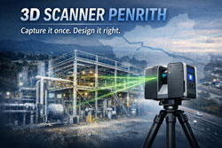
Modern engineering projects increasingly rely on accurate digital representations of existing infrastructure before design, fabrication, or modification begins. One of the most powerful technologies enabling this is LiDAR scanning (Light Detection and Ranging).
At Hamilton By Design, LiDAR scanning is used to capture engineering-grade point cloud data of industrial facilities, mining infrastructure, processing plants, and mechanical systems across Australia.
Understanding the accuracy of LiDAR scanning is essential for engineers, project managers, and asset owners when planning upgrades or modifications to existing facilities.
What is LiDAR Scanning?
LiDAR scanning works by emitting thousands of laser pulses per second. These pulses strike surrounding surfaces and return to the scanner, allowing precise calculation of distance.
The result is a dense three-dimensional point cloud that captures the exact geometry of an environment.
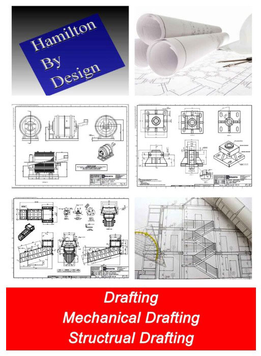
This digital dataset can then be used for:
• Engineering modelling
• Plant layout verification
• Clash detection
• Structural analysis
• Reverse engineering
• Retrofit design
At Hamilton By Design, these datasets are commonly converted into engineering models and SolidWorks design geometry using our established workflow.
Learn more about this process here:
Point Cloud to Engineering Model Workflow
https://www.hamiltonbydesign.com.au/point-cloud-to-engineering-model-workflow/
Typical Accuracy of Engineering LiDAR Scanning
The accuracy of LiDAR scanning depends on several factors including the scanner type, range to the object, scanning environment, and control methodology.
Typical engineering-grade terrestrial LiDAR systems achieve:
| Parameter | Typical Accuracy |
|---|---|
| Scanner measurement accuracy | ±1 mm to ±3 mm |
| Registered scan network accuracy | ±2 mm to ±6 mm |
| Large plant scan accuracy | ±5 mm to ±10 mm |
For most industrial engineering applications, this level of accuracy is more than sufficient to support:
• Structural steel modifications
• Pipework routing and tie-ins
• Mechanical equipment installation
• Conveyor and materials handling upgrades
• Plant shutdown engineering works
Factors That Affect LiDAR Accuracy
Although LiDAR scanning can achieve extremely high accuracy, several practical factors influence final results.
Scan Resolution
Higher resolution scanning increases the number of measured points and improves detail, but also increases processing time and file size.
Distance to Target
Accuracy decreases slightly as the distance between the scanner and the object increases. Industrial scanning programs typically maintain distances between 5–40 metres.
Scan Registration
Multiple scans must be aligned together to form a complete dataset. Proper registration and survey control ensures that the final point cloud remains accurate across large areas.
Surface Conditions
Highly reflective, transparent, or moving surfaces may introduce noise or missing data within the scan.
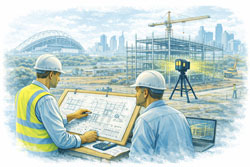
Why Accuracy Matters for Engineering Projects
Engineering projects often involve modifying existing assets that may have been constructed decades ago.
Original drawings may be missing, outdated, or inaccurate.
By capturing true existing conditions, LiDAR scanning reduces risk during design and construction.
Benefits include:
• Reduced site rework
• Fewer installation clashes
• Faster shutdown execution
• Improved fabrication accuracy
• Reduced project uncertainty
This is why many engineering teams now perform scanning before commencing plant upgrades.
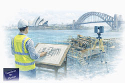
Capture Existing Conditions Before Plant Upgrades
https://www.hamiltonbydesign.com.au/capture-existing-conditions-before-plant-upgrades/
LiDAR Scanning for Mining and Industrial Infrastructure
Industries where LiDAR scanning is particularly valuable include:
• Mining and mineral processing
• Water and wastewater facilities
• Power generation plants
• Heavy manufacturing facilities
• Materials handling systems
At Hamilton By Design, scanning is commonly used to support:
• Shutdown planning
• Structural modifications
• Mechanical equipment upgrades
• Brownfield engineering projects
Learn more about our scanning services across Australia:
Engineering Grade 3D Laser Scanning for Mining and Industrial Projects
https://www.hamiltonbydesign.com.au/home/engineering-grade-3d-laser-scanning-mining-industrial/
From Scan Data to Engineering Design
Once captured, LiDAR data becomes the foundation for digital engineering workflows.
Point clouds can be converted into:
• SolidWorks models
• Structural steel models
• Pipe routing layouts
• Mechanical equipment models
• Digital twins of plant infrastructure
This allows engineers to design modifications directly against the existing environment, dramatically reducing project risk.

Conclusion
LiDAR scanning has become an essential tool for modern engineering projects, providing millimetre-level accuracy when capturing existing infrastructure.
When combined with experienced engineering workflows, LiDAR enables faster, safer, and more reliable plant upgrades.
At Hamilton By Design, we specialise in transforming high-accuracy LiDAR data into practical engineering models and design solutions for mining, industrial, and infrastructure projects.
Need LiDAR Scanning for Your Project?
Hamilton By Design provides engineering-grade 3D laser scanning services across Australia to support plant upgrades, shutdown projects, and infrastructure modifications.
Learn more about our services here: