Static Line Installation and Engineering Certification for Mining and Industrial Facilities

Hamilton By Design static line installation and engineering certification for mining and industrial facilities showing workers at height, structural engineering assessment, LiDAR scanning and installation support.

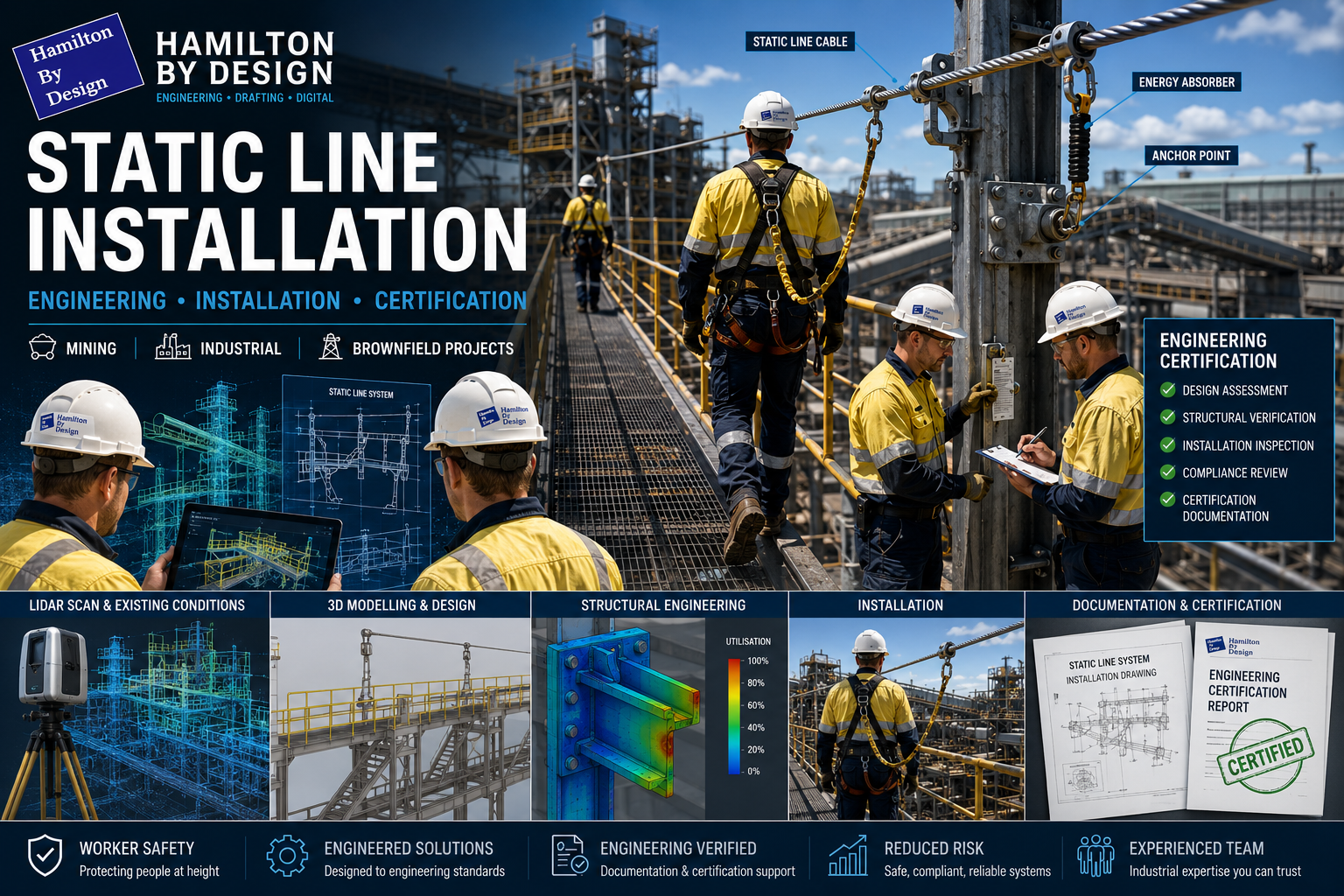
Static line systems play an important role in protecting personnel working at heights across mining, manufacturing, processing plants, smelters and heavy industrial environments. While a static line system may appear simple, effective implementation requires significantly more than installing a cable between two points.

A static line system is an engineered safety system requiring assessment of supporting structures, installation planning, documentation and engineering verification to ensure safe operation throughout its service life.

Why Engineering Assessment Matters

Static line systems can transfer significant loads into supporting structures during operation and potential fall events. Existing platforms, structural steel, roof systems and access structures may not have originally been designed for these additional loading conditions.

Potential risks may include:

  • Structural overload
  • Excessive cable deflection
  • Anchor point failure
  • Reduced fall clearance
  • Interference with plant infrastructure
  • Installation conflicts with existing services

Engineering assessment helps ensure the complete system performs safely and integrates correctly with existing facility infrastructure.


Brownfield Installation Challenges

Many industrial facilities have undergone modifications over many years and existing drawings do not always reflect current site conditions.

Common challenges include:

  • Structural changes not reflected in drawings
  • Additional pipework and services
  • Restricted installation access
  • Congested steelwork layouts
  • Equipment interferences
  • Unknown structural details

Capturing existing conditions before installation can reduce uncertainty and improve design confidence.

Engineering-grade LiDAR scanning and site verification can assist with:

  • Existing-condition capture
  • Structural geometry verification
  • Access assessment
  • Clash identification
  • As-built modelling
  • Installation planning

Typical Static Line Engineering Process

Site Inspection and Existing Asset Review

The process generally begins with:

  • Site inspections
  • Existing drawing review
  • Structural assessment
  • Access reviews
  • Existing-condition verification
  • Asset condition assessment

3D CAD Modelling Australia service banner for Hamilton By Design

Structural Engineering Assessment

Supporting structures are assessed for:

  • Structural member capacity
  • Connection capacity
  • Anchor loading requirements
  • Dynamic loading conditions
  • Multiple-user requirements
  • Deflection limits
  • Existing loading conditions
  • Corrosion and asset condition

Where required, structural modifications or strengthening works may be developed.


Design Documentation

Typical engineering deliverables may include:

  • Static line layouts
  • General Arrangement (GA) drawings
  • Structural details
  • Anchor point details
  • Installation drawings
  • Load calculations
  • Fabrication documentation

Clear documentation reduces installation uncertainty and assists construction and maintenance activities.


Installation Verification

Following installation, verification activities may include:

  • Anchor inspections
  • Fixing verification
  • Installation checks
  • Dimensional confirmation
  • Asset tagging
  • Documentation review

Engineering Certification

Engineering certification documentation may include:

  • Design calculations
  • Compliance documentation
  • Inspection records
  • Installation drawings
  • Certification statements
  • Asset schedules
  • Maintenance requirements

Certification provides confidence that the installed system aligns with engineering design intent and project requirements.


How Hamilton By Design Can Support Static Line Projects

Hamilton By Design has a team capable of supporting the design, fabrication, installation and engineering certification process for static line systems and working-at-height access solutions for mining and industrial facilities.

Our engineering-led approach may include:

  • Existing-condition site inspections
  • Engineering-grade LiDAR scanning and verification
  • Structural and mechanical assessment
  • Static line and anchor layout development
  • Fabrication drawings and installation documentation
  • Site coordination and construction support
  • Engineering review and certification documentation

Whether for new installations or brownfield modifications, our objective is to deliver systems designed and installed to relevant engineering requirements and project standards while integrating with existing infrastructure.

This provides clients with a complete workflow from concept and site capture through to installation support and engineering verification.


Benefits of an Engineered Approach

A structured engineering approach can provide:

  • Improved worker safety
  • Reduced project risk
  • Better installation outcomes
  • Reduced rework
  • Improved documentation
  • Increased confidence in long-term asset performance
  • Improved lifecycle management

Final Thoughts

Static line systems are critical safety assets and should be treated as engineered systems rather than standalone products. Proper installation, engineering assessment and certification help ensure systems perform as intended and integrate safely within operating facilities.

For mining and industrial environments, combining engineering assessment with existing-condition verification and structured project documentation can significantly reduce uncertainty and improve installation outcomes.

Hamilton By Design logo displayed on a blue tilted rectangle with a grey gradient background
3D LiDAR scanning and 3D modelling service button โ€” laser scanner capturing a point cloud for engineering and CAD modelling
Mechanical engineering services
Name
Would you like us to arrange a phone consultation for you?
Address
Finite Element Analysis (FEA) engineering simulation button
Mechanical engineering services

AS 1755 Conveyor Safety

Engineer reviewing a guarded conveyor system with fixed side and nip-point guards designed to prevent access to moving parts.

Designing Conveyor Guarding for Compliance, Safety, and Practical Operation

Conveyors are widely used across processing, manufacturing, and materials-handling environments, but they also present some of the most persistent safety risks in industrial operations. Entrapment, nip points, rotating components, and maintenance access are all recognised hazards that must be managed through proper design and guarding.

In Australia, these risks are addressed through AS 1755 โ€“ Conveyors โ€“ Safety Requirements, which establishes the minimum safety expectations for conveyor systems across their full lifecycle, from design and installation through to operation and maintenance.

This article outlines what AS 1755 requires, why compliant conveyor guarding is critical, and how engineering-led design plays a key role in achieving practical safety outcomes.


Bulk materials conveyor with compliant safety guarding at the hopper, tail end, and along the conveyor, shown with an engineer reviewing guarding design drawings.
3D LiDAR scanning and 3D modelling service button โ€” laser scanner capturing a point cloud for engineering and CAD modelling
Mechanical engineering services

What Is AS 1755?

AS 1755 is the Australian Standard that defines safety requirements for belt conveyors and other conveyor systems. It addresses both new and existing installations and applies to conveyors used in industrial, commercial, and processing environments.

Rather than focusing on individual guarding components in isolation, AS 1755 considers the conveyor system as a whole, including how people interact with it during normal operation, inspection, cleaning, and maintenance.

The standard is referenced by regulators, safety professionals, and engineers as the primary benchmark for conveyor safety in Australia.


Key Safety Principles in AS 1755

AS 1755 is built around a number of core safety principles that influence how conveyor guarding should be designed.

These include eliminating hazards where possible, controlling remaining risks through engineering solutions, and ensuring that guarding does not introduce new risks by restricting access or encouraging unsafe behaviour.

In practice, this means that compliant guarding must be effective, durable, and suitable for the operating environment, while still allowing conveyors to be inspected, cleaned, and maintained safely.


Conveyor Guarding Requirements

A major focus of AS 1755 is the control of access to hazardous areas. This includes guarding of:

  • Drive pulleys and tail pulleys
  • Return rollers and idlers
  • Nip points and shear points
  • Rotating shafts and couplings
  • Chain drives, belt drives, and gearboxes

Guarding must be designed so that body parts cannot access hazardous zones, taking into account reach distances, openings, and the position of the conveyor relative to walkways or platforms.

Importantly, AS 1755 recognises that guarding must be fit for purpose. Poorly designed guards that are difficult to remove, inspect, or maintain are often bypassed or removed altogether, creating new safety risks.


Fixed Guards vs Interlocked Guards

AS 1755 allows for different types of guarding depending on the application and risk profile.

Fixed guards are commonly used where access is not required during normal operation. These guards must be securely fixed and require tools for removal.

Interlocked guards may be required where regular access is necessary. These systems ensure that the conveyor cannot operate while the guard is open or removed, reducing the risk of exposure to moving parts.

Selecting the appropriate guarding strategy requires an understanding of how the conveyor is used in practice, not just how it appears on drawings.


Existing Conveyors and Retrofit Challenges

Many conveyors currently in service were installed before the latest versions of AS 1755 were adopted. In these cases, compliance is often achieved through retrofit guarding rather than full replacement.

Retrofitting guarding to existing conveyors introduces additional challenges, including:

  • Limited space around existing equipment
  • Incomplete or outdated drawings
  • Structural constraints
  • Ongoing operation during upgrades

Engineering-led assessment and accurate documentation of existing conditions are critical when designing retrofit guarding solutions that comply with AS 1755 without disrupting operations.


The Role of Engineering in Conveyor Guarding Design

AS 1755 does not provide prescriptive โ€œone-size-fits-allโ€ guard designs. Instead, it sets performance requirements that must be interpreted and applied by competent professionals.

Engineering input is essential to ensure that conveyor guarding:

  • Addresses all relevant hazards
  • Integrates with existing mechanical and structural systems
  • Can be fabricated and installed accurately
  • Supports safe maintenance and inspection activities

Poorly engineered guarding may appear compliant on paper but fail in real-world use.


Documentation, Verification, and Ongoing Safety

Compliance with AS 1755 is not a one-time activity. Conveyor systems evolve over time as layouts change, equipment is upgraded, and operating practices shift.

Clear documentation of guarding design, installation, and assumptions provides a baseline for future modifications and safety reviews. This documentation is also critical when demonstrating due diligence to regulators or during incident investigations.


Why AS 1755 Matters

AS 1755 exists to prevent serious injuries and fatalities associated with conveyor systems. When applied correctly, it provides a structured framework for identifying hazards, implementing effective controls, and maintaining safe operation over the life of the equipment.

Achieving compliance requires more than installing mesh around moving parts. It requires understanding how people interact with conveyors and designing guarding that supports safe behaviour rather than working against it.


Hamilton By Design logo displayed on a blue tilted rectangle with a grey gradient background

Conveyor guarding designed in accordance with AS 1755 is a critical component of safe industrial operations. Engineering-led design, accurate documentation, and practical consideration of maintenance and operation are essential to achieving compliance that works in practice.

When conveyor safety is treated as an engineering problem rather than a checkbox exercise, the result is safer equipment, fewer incidents, and more reliable operations.

Manufacturing and production services button

Our clients


Name
Would you like us to arrange a phone consultation for you?
Address

3D CAD Modelling Australia service banner for Hamilton By Design


CHPP Engineering title graphic featuring bold white text reading "CHPP Engineering" centred on a blue rounded rectangle background.
Pipework Drafting title graphic featuring bold white text reading "Pipework Drafting" centred on a blue rounded rectangle background.
3D LiDAR Scanning for Engineering Projects title graphic featuring bold white text on a blue rounded rectangle background.


Finite Element Analysis (FEA) engineering simulation button
Structural drafting services button
Mechanical drafting services button


Australian Drafting logo featuring bold white text reading "Australian Drafting" centred on a blue rounded rectangle background.
Engineering Governance title graphic featuring bold white text reading "Engineering Governance" centred on a blue rounded rectangle background.
Engineering-Grade LiDAR Scanning title graphic featuring bold white text on a blue rounded rectangle background.


Mechanical drafting services button
Structural drafting services button


Fabrication and product design services
3D CAD Modelling Australia service banner for Hamilton By Design
Mechanical, Structural & Pipework Drafting service banner by Hamilton By Design featuring white text on a blue background.


3D LiDAR scanning and 3D modelling service button โ€” laser scanner capturing a point cloud for engineering and CAD modelling
Mechanical engineering services