From Reality to Fabrication

From Reality to Fabrication: Engineering-Led 3D Modelling, Structural Verification and Build-Ready Documentation

In industrial and infrastructure projects, success is rarely determined by intent alone. It is determined by how accurately existing conditions are understood, how rigorously designs are validated, and how clearly fabrication information is communicated. At Hamilton By Design, we bridge the gap between site reality and fabrication by combining engineering-led 3D modelling, structural engineering, finite element analysis (FEA), and fabrication-ready documentation into a single, accountable workflow.

This integrated approach ensures that what is designed can be built, fits the first time, and performs as intended in service.

3D Modelling for Fabrication: Designing What Can Actually Be Built

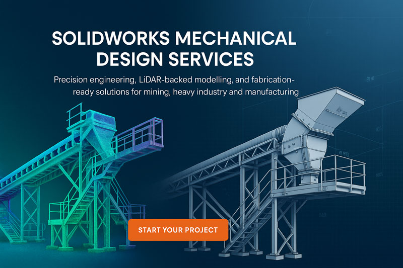
3D modelling for fabrication is not simply about producing visually accurate geometry. It is about creating models that reflect real-world constraints, manufacturing tolerances, installation access, and structural behaviour. Hamilton By Design develops fabrication-grade 3D CAD models that are built around how components will be cut, welded, machined, lifted, and installed.

Our models are typically informed by site measurements, laser scanning, and as-built data to ensure alignment with existing structures and equipment. This is particularly critical in brownfield environments such as processing plants, material handling facilities, and industrial upgrades where assumptions based on legacy drawings are unreliable.

Each model is developed with downstream use in mind. Hole sizes, weld preparations, plate thicknesses, member sizes, and connection details are defined so fabricators can confidently transition from model to manufacture without reinterpretation or rework.

Structural Engineering Embedded in the Modelling Process

Structural engineering at Hamilton By Design is not a separate, downstream exercise. It is embedded directly within the 3D modelling process. Structural load paths, support conditions, connection behaviour, and serviceability requirements are considered as the model evolves, not after geometry is frozen.

This integrated method allows structural considerations to inform design decisions early, reducing late-stage redesigns and cost escalation. It also ensures compliance with relevant Australian Standards and industry-specific requirements, whether the project involves steel structures, plant support frames, access platforms, equipment foundations, or retrofit works.

By developing the structural model in parallel with the fabrication model, we maintain alignment between engineering intent and physical deliverables.

Finite Element Analysis: Verifying Performance, Not Guessing

Finite Element Analysis (FEA) plays a critical role in validating that a design will perform safely and efficiently under real operating conditions. Hamilton By Design applies FEA to assess stresses, deflections, load sharing, vibration response, and fatigue risk across a wide range of industrial applications.

FEA is particularly valuable where traditional hand calculations are insufficient or overly conservative. Complex geometries, dynamic loading, eccentric supports, impact forces, and non-uniform load distributions can all be assessed with greater confidence using simulation-based analysis.

Our FEA workflows are directly linked to the 3D CAD models used for fabrication. This ensures consistency between the analysed geometry and the manufactured outcome. Where analysis identifies areas of concern, design modifications are implemented directly in the model, creating a closed-loop engineering process that improves both safety and constructability.

As-Built Documentation: Capturing What Exists, Not What Was Assumed

Accurate as-built documentation is fundamental to effective engineering decision-making. In many facilities, original drawings are outdated, incomplete, or no longer representative of the installed condition. Hamilton By Design produces engineering-grade as-built documentation that reflects the true geometry and configuration of existing assets.

As-built documentation may include 3D models, general arrangement drawings, sectional views, and measured dimensions that form a reliable baseline for future upgrades, maintenance planning, and compliance assessments. This information reduces uncertainty, supports safer design decisions, and enables more efficient project planning.

For clients managing long-life assets, high-quality as-built data becomes a strategic resource rather than a one-off deliverable.

Fabrication Drawings That Reduce Risk on the Workshop Floor

Fabrication drawings are the point where engineering intent meets manufacturing reality. Poorly defined drawings lead to RFIs, delays, rework, and disputes. Hamilton By Design produces clear, unambiguous fabrication drawings that fabricators can trust.

Our drawings typically include detailed part drawings, assembly drawings, weld symbols, material specifications, tolerances, and notes aligned with the approved engineering model. Because these drawings are derived directly from fabrication-ready 3D models that have been structurally verified, inconsistencies between design and manufacture are minimised.

This approach supports faster fabrication turnaround, improved quality control, and smoother installation on site.

A Single, Accountable Engineering Workflow

One of the key advantages of Hamilton By Designโ€™s approach is single-source accountability. By delivering 3D modelling for fabrication, structural engineering, FEA, as-built documentation, and fabrication drawings within a unified workflow, we remove the handover gaps that often exist between consultants, designers, and fabricators.

Clients benefit from clearer communication, reduced coordination risk, and designs that are technically sound, buildable, and aligned with operational requirements. Fabricators benefit from models and drawings that reflect real conditions and engineering intent. Asset owners benefit from safer, more reliable outcomes delivered with fewer surprises.

Hamilton By Design logo displayed on a blue tilted rectangle with a grey gradient background

Engineering That Stands Up in the Real World

At Hamilton By Design, engineering is not about producing documents in isolation. It is about delivering outcomes that work in the real worldโ€”on site, in fabrication workshops, and over the life of an asset. By integrating 3D modelling for fabrication with structural engineering, finite element analysis, as-built documentation, and fabrication drawings, we provide a robust foundation for successful industrial projects.

This engineer-led, fabrication-focused approach ensures that designs are not only accurate on screen, but reliable, buildable, and fit for purpose in operation.

Our clients:


Name
Would you like us to arrange a phone consultation for you?
Address

3D CAD Modelling | 3D Scanning

Hamilton By Design

3D Scanning Engineering Simplified in Kalgoorlieโ€“Boulder

3D Scanning Engineering Simplified in Kalgoorlieโ€“Boulder

Kalgoorlieโ€“Boulder is unlike any other city in Australia. Built on one of the richest goldfields on Earth, it remains a powerhouse of heavy industry, large-scale mining, metallurgical processing, mechanical maintenance and fabrication. With vast open-cut mines, underground networks, processing plants, workshops, rail infrastructure and expanding industrial precincts, the region demands precision, resilience and engineering that can stand up to harsh environmental conditions.

Hamilton By Design supports these exact needs with 3D LiDAR laser scanning, advanced engineering services, accurate 3D CAD modelling, and fabrication-ready drafting. For brownfield upgrades, shutdown planning, structural assessment or new installations, we simplify engineering by delivering millimetre-accurate digital data and industry-grade design documentation.


Why Kalgoorlieโ€“Boulder Is Unique for Engineering Projects

Kalgoorlieโ€“Boulder is shaped by extreme conditions and complex industrial systems. Its uniqueness comes from:

1. One of the world’s largest open-cut mines

The Super Pit and surrounding operations involve large-scale mechanical systems, crushers, conveyors, structural platforms, heavy mobile equipment and intricate processing facilities. These environments change frequently as operations evolve, making as-built accuracy critical.

2. Harsh, abrasive and high-wear environments

Dust, vibration, heat and heavy loading accelerate wear on structural steel, machinery and plant systems. Engineering assessments and redesigns must factor in high fatigue cycles and abrasive service.

3. A dense concentration of fabrication & maintenance workshops

Kalgoorlieโ€“Boulder supports workshops specialising in mill relining, crusher repairs, structural fabrication, heavy-haul equipment maintenance and mining components. These businesses rely on accurate geometry for reverse-engineering and fit-out of parts.

4. Constant brownfield upgrades

Processing plants, conveyors, crushers, pump stations and underground infrastructure undergo frequent modificationsโ€”making 3D scanning and digital twins essential for reducing shutdown time and project risk.

5. Remote-region reliability demands

Any mistake in fabrication or installation results in delays, lost production and major cost impacts. Thatโ€™s why engineering certainty is paramount.


How Hamilton By Design Supports Kalgoorlieโ€“Boulder Industries

We bring an engineer-led, accuracy-driven approach to projects across gold processing plants, mining workshops, underground facilities, industrial yards and remote infrastructure.


High-Accuracy 3D LiDAR Laser Scanning

Our first step is capturing your site or equipment with millimetre-level precision using 3D laser scanning. This allows your team to design, fabricate and install with full confidence. Laser scanning is perfect for crushers, platforms, conveyor systems, tanks, mechanical rooms, structural steel and plant upgrades.

Learn more here:
3D Laser Scanning

Benefits for Kalgoorlieโ€“Boulder include:

  • Reduced downtime during shutdowns
  • No need for repeat site visits
  • Accurate tie-in points for brownfield modifications
  • Clear visibility of alignment issues, deflections and wear
  • Safe data capture in challenging environments

Intelligent 3D CAD Modelling for Mining & Industrial Assets

Once scanned, we convert the point cloud into accurate 3D CAD models suitable for engineering analysis, fabrication and layout planning.

Learn more here:
3D CAD Modelling

This enables:

  • Clash detection before fabrication
  • Reverse-engineering of components
  • Visualisation of complex plant areas
  • Better coordination between engineers, fabricators & installers

Perfect for rebuilds, relocations, shutdown works and equipment optimisation.


Engineering & FEA for Mining-Grade Demands

Kalgoorlieโ€“Boulderโ€™s high-load and high-fatigue environments require engineering that goes beyond standard design. Hamilton By Design provides mechanical and structural assessment, optimisation, and FEA-based verification.

Learn more here:
FEA Capabilities

Our analysis supports:

  • Structural steelwork validation
  • Chute, tank and vessel assessments
  • Conveyor and machinery load cases
  • Fatigue and vibration studies
  • Repair strategy development

This ensures your equipment remains safe, compliant and production-ready.


Fabrication-Ready Drafting for Workshops & Site Installations

From detailed drawings to GA layouts and isometrics, we deliver drafting packages suited for mining workshops, fabrication yards and onsite installation teams.

Learn more here:
Drafting Services

We provide:

  • Workshop drawings
  • Structural detailing
  • Mechanical layouts
  • Piping/isometric drawings
  • As-built drawing updates

Clear documentation means fewer fabrication errors, less rework and a smoother installation process.


Real-World Use Cases in Kalgoorlieโ€“Boulder

Hamilton By Design supports projects such as:

  • Plant expansion and shutdown upgrades
  • Crusher and conveyor rebuilds
  • Structural assessments and remediations
  • Mill, tank and chute upgrades
  • Workshop fit-outs and equipment design
  • Remote infrastructure and facility upgrades

With accurate scanning, engineering certainty and integrated modelling, your team can make confident decisions at every stage.


Hamilton By Design logo displayed on a blue tilted rectangle with a grey gradient background

Why Hamilton By Design Is a Strong Fit for Kalgoorlieโ€“Boulder

  • Engineer-led scanning ensures precision and technical oversight
  • Mining-grade modelling and engineering
  • Reduced rework, faster fabrication and safer installations
  • End-to-end workflow from scan โ†’ model โ†’ engineer โ†’ draft
  • Ideal for remote or high-complexity environments

Kalgoorlieโ€“Boulder projects demand reliability, clarity and accuracy โ€” and thatโ€™s exactly what we deliver.

Our Clients

Name
Would you like us to arrange a phone consultation for you?
Address

SolidWorks Mechanical Design Services

Hero image showing a LiDAR-coloured point-cloud model of an industrial conveyor system on the left transitioning into a detailed SolidWorks 3D CAD model on the right, with the heading โ€˜SolidWorks Mechanical Design Servicesโ€™ and a call-to-action button that reads โ€˜Start Your Projectโ€™

SolidWorks Design Services

The Many Faces of Mechanical Design: How SolidWorks Powers Modern Engineering Across Australia

At Hamilton By Design, we see the same pattern every day across mining, heavy industry, manufacturing, and complex brownfield environments: the quality of engineering outcomes depends directly on the quality of the models driving them. And when it comes to mechanical design, SolidWorks remains one of the most capable and versatile platforms on the planet.

From dragline components to sheet metal enclosures, from pressure vessel upgrades to bespoke robotics, SolidWorks enables engineers to turn ideas into precise, fabrication-ready models that reduce rework, eliminate uncertainty, and accelerate project delivery.

Below, we explore the full spectrum of mechanical design disciplines where SolidWorks excels โ€” and how Hamilton By Design uses this capability to deliver accurate, reliable, engineering-grade outcomes across Australia.


Why SolidWorks Remains the Backbone of Mechanical Design

SolidWorks brings together parametric modelling, simulation, large assembly performance, surfacing, sheet metal tools, weldments, routing and visualisation under a single environment. The result is powerful:

โœ” Engineering that is data-driven
โœ” Models that are precise and fabrication-ready
โœ” Assemblies that reflect true site conditions
โœ” Designs that respond intelligently to changes
โœ” Drawings that follow Australian Standards
โœ” Seamless integration with LiDAR-based as-builts

When paired with Hamilton By Designโ€™s LiDAR scanning workflows, SolidWorks becomes an engine for delivering zero-guesswork mechanical design.


Mechanical Design Disciplines Perfectly Suited to SolidWorks Modelling

SolidWorks supports a huge range of engineering tasks. Below is a deep dive into the disciplines where Hamilton By Design deploys it every day.


1. Machine Design: Precision for Moving Systems

SolidWorks is a natural fit for mechanical equipment upgrades and R&D design work, including:

  • Gearboxes, shafts, keys, couplings
  • Linear motion systems and actuators
  • Mechanical linkages, cams and levers
  • Robotic mechanisms
  • Safety guards, enclosures and subframes
  • Automation concept development

Whether weโ€™re modelling a drive assembly for a conveyor or designing a new piece of automated equipment, SolidWorks gives us full control over the mechanics, kinematics, clearances and manufacturability.


2. Structural Mechanical Design: Frames, Platforms & Fabrication

Mining and industrial plants rely heavily on welded structures and access systems. SolidWorks weldments excel at:

  • Platforms, walkways and stair systems
  • Equipment bases, skids and structural frames
  • Gantries, monorails and supports
  • Pipe supports and brackets
  • Structural reinforcements and upgrade scopes

Built-in cut lists, profile libraries and FEA ensure every frame is practical, safe and fabrication-ready.


3. Pressure Vessels, Tanks & Piping Systems

SolidWorks is an ideal tool for pressure-bound components and interconnected plant systems:

  • Tanks, vessels, bins and hoppers
  • Nozzles, flanges, stiffeners and ladders
  • Pipe routing and spooled sections
  • Chute systems, transitions and flow paths
  • Wear liners and maintenance-friendly redesigns

With stress linearisation, buckling analysis and accurate geometry import from LiDAR scans, we ensure designs meet engineering intent and fit up perfectly on site.


4. Sheet Metal: From Light Fabrication to Industrial Ducting

SolidWorks is the industry standard for sheet metal components:

  • Ducting and HVAC transitions
  • Guards, housings and folded enclosures
  • Electrical cabinets
  • Chute panels
  • Laser-cut and folded brackets

Automatic flat patterns and K-factor control mean fewer mistakes at the plasma/laser cutters and more predictable outcomes for fabricators.


5. Heavy Industry & Mining Equipment Modelling

Hamilton By Designโ€™s roots in mining and heavy industry make SolidWorks invaluable for:

  • Conveyor components and guarding
  • Diverter chutes, hoppers and flow-optimised transitions
  • Bucket-wheel reclaimer parts
  • Crusher and screen upgrades
  • Dragline component modelling
  • Structural deformation/realignment scopes

Combined with LiDAR scanning, SolidWorks becomes the tool that eliminates shutdown fit-up problems.


6. Product Design & Industrial Design

SolidWorksโ€™ surfacing and parametric tools are ideal for:

  • Consumer products
  • Power tools and ergonomic items
  • Injection-moulded components
  • Kitchen or appliance prototypes
  • Concept development for early-stage R&D

It supports rapid iterations, rendering, and export for 3D printing.


7. Robotics & Automation Systems

With the rise of automated processing and Industry 4.0, SolidWorks continues to shine in:

  • End effectors
  • Robotic arms and actuators
  • Kinematic studies
  • Sensor housings
  • Concept layouts for automated cells

We frequently pair this with our LiDAR models of existing plants to create automation solutions that genuinely fit the space.


8. Tooling, Jigs & Fixtures

Fabrication and machining rely on accurate tooling, and SolidWorks helps us design:

  • Welding jigs
  • Machining fixtures
  • Assembly tooling
  • Positioning and inspection gauges
  • Drill guides and alignment tooling

Parametric updates make future modifications simple and consistent.


9. Material Handling Systems

Across mining, ports, agriculture and waste facilities, SolidWorks supports:

  • Conveyor layouts
  • Screw and chain conveyors
  • Transfer chute redesigns
  • Feeders, bins and flow systems
  • Skids and support structures

We routinely pair mechanical redesign with simulation, checking wear patterns, stresses and clearances.


10. Reverse Engineering & As-Built Modelling from LiDAR

This is where Hamilton By Design leads the industry.

We scan sites with millimetre-level LiDAR, then rebuild clean parametric models in SolidWorks for:

  • Brownfield upgrades
  • Fit-up verification
  • Clash detection
  • Replacements and like-for-like manufacturing
  • Structural deformation assessments
  • Shutdown planning

It is the combination of LiDAR + engineering + SolidWorks that gives clients complete confidence in their next project.


How Clients Benefit from SolidWorks-Driven Mechanical Design

โœ” Reduced rework

โœ” Faster shutdown upgrades

โœ” Accurate manufacturing drawings

โœ” Better communication between engineers, fabricators and site teams

โœ” Safer and more predictable installations

โœ” Clear, simulation-backed decision-making

From CHPPs to ports, from power stations to manufacturing plants, SolidWorks modelling allows Hamilton By Design to deliver engineering outcomes you can trust.


Hamilton By Design logo displayed on a blue tilted rectangle with a grey gradient background

Partner With Hamilton By Design for SolidWorks Mechanical Design

We support clients across:

  • NSW (Sydney, Newcastle, Central Coast, Hunter Valley)
  • QLD (Bowen Basin, Surat Basin, Mount Isa)
  • WA (Perth, Pilbara)
  • SA, VIC and regional Australia

If your next project needs mechanical accuracy, design certainty or LiDAR-integrated engineering, our team is ready to support you.

Name
Address
You would like to:

Our clients

SolidWorks

3D Laser Scanning

Engineering Projects

Engineering Services

3D Laser Scanning for Engineering

3-D Lidar Scanning Hunter Valley: Transforming Industrial Projects with Accuracy, Safety and Engineering Confidence

The Hunter Valley is one of Australiaโ€™s most strategically important industrial regions. It supports large mining operations, CHPP facilities, fabrication workshops, energy infrastructure, civil projects and heavy manufacturing. These industries depend on precision, safety and efficient project delivery โ€” yet most operate in aging brownfield environments where original drawings are outdated, equipment has shifted over time, and modifications have occurred for decades without accurate documentation.

In environments like these, traditional measuring methods often fail to provide the precision required for confident engineering and fabrication. This is why 3-D Lidar scanning in the Hunter Valley has become a critical tool for engineers, supervisors, fabricators and project managers. It captures the real-world site conditions with millimetre accuracy, creating a digital foundation for smarter, safer and more efficient project execution.

This article explores the benefits, pros and cons of 3-D Lidar scanning, and explains why the Hunter Valley is uniquely positioned to gain massive value from this technology.


Understanding 3-D Lidar Scanning

3-D Lidar (Light Detection and Ranging) scanning is a non-contact measurement technology that uses lasers to capture millions of points in seconds. The scanner emits laser pulses and measures the return time to determine distances, building a dense โ€œpoint cloudโ€ of the environment.

This point cloud is a precise 3-D representation of:

  • Structural steel
  • Conveyors and transfer towers
  • Chutes, bins and hoppers
  • Tanks, pipework and mechanical equipment
  • Platforms, walkways and buildings
  • Industrial plant rooms and process areas

Once captured, this digital data becomes the foundation for engineering models, fabrication drawings, digital fit checks and project planning.


Why 3-D Lidar Scanning Matters in the Hunter Valley

The Hunter Valley contains some of the most complex and heavily used industrial assets in Australia. Many facilities have been in operation for decades, and almost all have undergone modifications, expansions and repairs. Over time, the real-world geometry diverges significantly from the old drawings stored on paper or outdated CAD files.

This creates major challenges:

  • Measurements taken by hand are inaccurate or unsafe
  • Shutdown windows are extremely tight
  • Fabricators rely on precise data to avoid costly rework
  • Engineers require true geometry for load calculations and interface design
  • Supervisors need reliable information to scope replacement work

3-D Lidar scanning provides a millimetre-accurate representation of what exists onsite, removing guesswork and supporting engineering best practice.


The Benefits of 3-D Lidar Scanning in the Hunter Valley

1. Millimetre Accuracy Improves Engineering Outcomes

In heavy industrial environments, small measurement errors can create large, expensive problems. Structural misalignment, worn steel, bent frames, sagging conveyors and distorted chutes are all common in brownfield plants.

3-D Lidar scanning captures:

  • True dimensions
  • Variations from design
  • Deformation and misalignment
  • Complex curved surfaces
  • Differences caused by wear and tear

Engineers design with confidence because the digital model reflects actual site conditions โ€” not assumptions.


2. Huge Reduction in Rework and Fabrication Errors

Fabricators in Singleton, Muswellbrook, Rutherford, Tomago and throughout the Hunter region rely on accurate measurements to ensure steel and mechanical components fit the first time.

Without accurate data, common fabrication issues include:

  • Bolt holes misaligned
  • Steel members too short or too long
  • Chutes or hoppers not matching openings
  • Pipe spools missing clearances
  • Platforms not sitting square

These problems lead to:

  • Onsite cutting and welding
  • Delayed installations
  • Extended shutdown time
  • Additional crane costs
  • Extra labour expenses

3-D Lidar scanning eliminates these risks, ensuring every component is manufactured to match the as-built site geometry.


3. Improved Shutdown Planning and Faster Execution

Mining and CHPP shutdowns in the Hunter Valley operate under strict time constraints. Any unexpected measurement issue can cause delays affecting production and safety.

With 3-D Lidar scanning:

  • Scope is defined accurately before shutdown
  • Fabrication is completed correctly the first time
  • Digital fit checks identify problems early
  • Installation is faster and safer

Shutdowns become more predictable and efficient.


4. Massive Safety Improvements

Manual measurement often requires workers to:

  • Enter confined spaces
  • Access heights
  • Work around operating equipment
  • Lean over conveyors
  • Navigate dirty, uneven or hazardous areas

3-D Lidar scanning minimises physical access requirements. Technicians can scan large areas from safe positions, reducing:

  • Fall risks
  • Pinch-point exposure
  • Hot-work hazards
  • Time on elevated structures

This is a major benefit for HSE and maintenance teams across the Hunter Valley.


5. Better Communication, Collaboration and Visualisation

Point clouds and 3-D models make it easier for teams to understand the project environment, especially when stakeholders are spread across:

  • Mine sites
  • Fabrication workshops
  • Design offices
  • Engineering consultancies
  • Projects teams and OEM vendors

Digital data allows remote review, reducing the need for repeated site visits and improving decision-making.


6. Ideal for Brownfield Upgrades and Congested Areas

Many Hunter Valley facilities are decades old, with layers of modifications. Clearances are tight, geometry is irregular, and equipment alignment has changed over the years.

3-D Lidar scanning is perfect for:

  • Transfer towers with layered steel
  • Congested plant rooms
  • Pipe networks
  • Stockpile conveyors
  • Old building footprints
  • Complex structural junctions

The scanner captures the complexity instantly and precisely.

Hamilton By Design logo displayed on a blue tilted rectangle with a grey gradient background

Pros and Cons of 3-D Lidar Scanning

While 3-D Lidar scanning is a game-changing tool, it is important to understand both the advantages and limitations.

3D Scanning in The Hunter Valley

3D Laser Scanning

Hunter Valley Laser Scanning: Transforming Engineering Accuracy Across Mining, Manufacturing and Infrastructure

3D Laser Scanning in Singleton and the Hunter: Delivering Accuracy for Mining, Manufacturing and Industrial Projects

Laser Scanning Hunter Valley: Delivering Engineering-Grade Accuracy for Mining, Manufacturing and Industrial Projects

Name
Address
You would like to:

Engineering Confidence: Using FEA to Validate Real-World Designs

Mechanical engineering has always been a balance between creativity and certainty.
Every bracket, frame, chute, or structural support we design must perform under real loads, temperatures, and conditions โ€” often in environments where failure simply isnโ€™t an option.

Thatโ€™s where Finite Element Analysis (FEA) earns its place as one of the most powerful tools in modern design. It allows engineers to move from assumption to verification โ€” transforming the way we predict, test, and optimise mechanical systems.


What Is FEA โ€” and Why It Matters

FEA divides complex geometry into a network of small, interconnected elements.
By solving the physical equations that govern stress, strain, and displacement across those elements, engineers can predict how a structure behaves under load, vibration, or temperature.

Instead of relying solely on hand calculations or over-built safety factors, FEA provides quantitative insight into performance โ€” letting us see where structures flex, where stress concentrates, and how design choices affect real-world outcomes.

In mechanical engineering, that means fewer prototypes, lower material costs, and far greater design confidence.


1. Static Analysis โ€” The Foundation of Structural Validation

Static linear analysis is the foundation of most FEA work.
It evaluates how a structure responds to steady, time-independent loads such as gravity, pressure, or fixed equipment weight.

Through static analysis, engineers can:

  • Visualise stress and displacement distribution across a part or assembly.
  • Evaluate safety factors under different loading conditions.
  • Check stiffness and material utilisation before fabrication.
  • Identify weak points or stress concentrations early in design.

This baseline validation is the difference between a design that โ€œshouldโ€ work and one that will.


2. Assembly-Level Simulation โ€” Seeing the Whole System

Few machines fail because a single part breaks.
Most failures happen when components interact under load โ€” bolts shear, brackets twist, or welds experience unplanned tension.

FEA allows engineers to simulate entire assemblies, including:

  • Contact between parts (bonded, sliding, or frictional).
  • Realistic boundary conditions such as bearings, springs, or pinned joints.
  • The influence of welds, fasteners, or gaskets on overall performance.

This system-level view helps mechanical engineers design not only for strength, but also for compatibility and reliability across the full structure.


3. Mesh Control โ€” Accuracy Where It Counts

A simulation is only as good as its mesh.
By controlling element size and density, engineers can capture critical detail in stress-sensitive regions like fillets, bolt holes, and weld toes.

Modern FEA tools use adaptive meshing โ€” refining the model automatically in areas of high stress until the solution converges.
That means precise, efficient results without excessive computation time.


4. Thermal-Structural Interaction โ€” When Heat Becomes a Load

Many mechanical systems face thermal as well as mechanical challenges.
Whether itโ€™s ducting in a process plant or hoppers near heat sources, temperature gradients can cause expansion, distortion, or thermal stress.

FEA allows engineers to:

  • Model steady-state or transient heat transfer through solids.
  • Apply convection, radiation, or temperature boundary conditions.
  • Combine thermal and structural analyses to study thermal expansion and thermal fatigue.

Understanding how heat and load combine helps ensure equipment remains stable, safe, and accurate throughout its lifecycle.


5. Modal and Buckling Analysis โ€” Designing Against Instability

Some risks are invisible until theyโ€™re simulated.
Vibration and buckling are two of the most overlooked โ€” yet most common โ€” causes of structural failure.

Modal Analysis

Determines a structureโ€™s natural frequencies and mode shapes, helping designers avoid resonance with operating machinery, fans, or conveyors.

Buckling Analysis

Predicts the critical load at which slender members or thin-walled panels lose stability โ€” allowing engineers to reinforce and optimise designs early.

By identifying these limits before fabrication, engineers can prevent problems that are expensive and dangerous to discover on site.


Design Optimisation โ€” Smarter, Lighter, Stronger

Good design is rarely about adding material; itโ€™s about using it wisely.
FEA supports parametric and goal-based optimisation, enabling engineers to vary geometry, thickness, or material and automatically test multiple configurations.

You can set objectives such as:

  • Minimising weight while maintaining strength.
  • Reducing deflection under fixed loads.
  • Optimising gusset or flange size for stiffness.

This process of โ€œdigital lightweightingโ€ drives better performance and cost efficiency โ€” especially valuable in industries where both material and downtime are expensive.


7. Communication and Confidence

FEA isnโ€™t only a calculation tool โ€” itโ€™s a communication tool.
Colour-coded plots, animations, and automated reports make it easier to explain complex mechanical behaviour to project managers, clients, or certifying bodies.

Clear visuals turn stress distributions and displacement fields into a shared language โ€” helping stakeholders understand why certain design choices are made.


Real-World Applications Across Mechanical Engineering

ApplicationType of AnalysisKey Benefit
Chutes & HoppersStatic + BucklingConfirm wall thickness and frame design for structural load and vibration
Conveyor FramesModal + StaticAvoid resonance and ensure adequate stiffness
Pressure EquipmentThermal + StaticEvaluate thermal stress and hoop stress under load
Machine BracketsStatic + OptimisationReduce weight while maintaining rigidity
Platforms & GuardingBucklingValidate stability under safety loading
Welded Frames & SupportsStaticCheck deformation, stress, and weld performance

These examples show how FEA becomes an everyday design partner โ€” embedded in the workflow of mechanical engineers across manufacturing, resources, and infrastructure.


The Engineerโ€™s Advantage: Data Over Assumption

In traditional design, engineers often relied on prototypes and conservative safety factors.
Today, simulation delivers the same assurance โ€” without the waste.

By applying FEA early in the design cycle, mechanical engineers can:

  • Predict failure modes before they occur.
  • Shorten development time.
  • Reduce material usage.
  • Justify design decisions with quantitative proof.

FEA enables engineers to focus less on guesswork and more on innovation โ€” designing structures that are both efficient and dependable.


Engineering Integrity in Practice

At Hamilton By Design, we integrate FEA into every stage of mechanical design and development.
Itโ€™s how we ensure that every frame, chute, and mechanical system we deliver performs as intended โ€” safely, efficiently, and reliably.

We use FEA not just to find the limits of materials, but to push the boundaries of design quality โ€” delivering engineering solutions that last in the toughest industrial environments.

Design backed by data isnโ€™t a slogan โ€” itโ€™s how we engineer confidence.


Building a Culture of Verified Design

When FEA becomes part of everyday engineering culture, it changes how teams think.
Designers begin to see structures not just as drawings, but as living systems under real forces.

That shift builds trust โ€” between engineer and client, between concept and reality.
Itโ€™s what defines the future of mechanical design: informed, optimised, and proven before the first bolt is tightened.

From 3D Scanning to Digital Twins: The Next Step in Mining Data

Mining is evolving faster than ever.
What was once an industry defined by physical muscle โ€” haul trucks, crushers, conveyors โ€” is now being transformed by data intelligence, digital modelling, and real-time insight.

At the heart of this transformation lies a quiet revolution: 3D scanning.
Once used primarily for design verification or plant modification, scanning is now the gateway technology that feeds the emerging world of digital twins โ€” live, data-driven replicas of mine assets that help engineers predict, plan, and optimise before problems occur.

At Hamilton By Design, weโ€™ve spent years scanning and modelling chutes, hoppers, and material-handling systems across Australiaโ€™s mining sector. Each project has shown us one thing clearly:

Scanning isnโ€™t just about geometry โ€” itโ€™s about knowledge.
And digital twins are the next logical step in turning that knowledge into action.


What Exactly Is a Digital Twin?

Think of a digital twin as the digital counterpart of a physical asset โ€” a chute, a conveyor, a processing plant, even an entire mine site.

Itโ€™s not a static 3D model; itโ€™s a dynamic, data-linked environment that mirrors the real system in near real time.
Sensors feed performance data into the twin: wear rates, temperature, vibration, flow speed, throughput. The twin then responds, updating its state and allowing engineers to simulate scenarios, forecast failures, and test design changes before touching the physical equipment.

In essence, a digital twin gives you a real-time window into the life of your assets โ€” one thatโ€™s predictive, not reactive.


How 3D Scanning Powers the Digital Twin

To create a digital twin, you first need an accurate foundation โ€” and thatโ€™s where 3D scanning comes in.
The twin can only be as good as the geometry beneath it.

Laser scanning or LiDAR technology captures millimetre-accurate measurements of chutes, hoppers, crushers, conveyors, and processing structures.
This creates a precise 3D โ€œas-isโ€ model โ€” not what the plant was designed to be, but what it actually is after years of wear, repair, and modification.

That baseline geometry is then aligned with:

  • Operational data from sensors and PLCs (e.g. flow rates, temperatures, vibrations)
  • Material behaviour data from CFD and wear simulations
  • Design intent data from CAD and engineering archives

Once these layers are synchronised, the model becomes a living system โ€” continuously updated, measurable, and comparable to its physical twin.

You can see how we capture and prepare that foundation in our detailed article:
3D Scanning Chutes, Hoppers & Mining


From Reactive Maintenance to Predictive Performance

In most operations today, maintenance still works on a reactive cycle โ€” wait for a fault, shut down, repair, restart.
Itโ€™s expensive, unpredictable, and risky.

With digital twins, that model flips.
Instead of waiting for wear to become a failure, the twin uses real-time and historical data to forecast when parts will reach their limits.
The result is predictive maintenance โ€” planning shutdowns based on evidence, not emergency.

Imagine being able to simulate how a chute will behave under new flow conditions, or when a liner will reach its critical wear thickness, before you commit to a shutdown.
Thatโ€™s not future-speak โ€” itโ€™s what forward-thinking operators are doing right now.

Every hour of avoided downtime can mean tens or even hundreds of thousands of dollars saved.
Even a modest 5 % reduction in unplanned outages can add millions to annual output.


Integrating Scanning, Simulation, and Sensors

A full digital-twin workflow in mining usually includes four steps:

  1. Capture: 3D scanning provides the exact geometry of the asset.
  2. Model: Engineers integrate the geometry with CAD, CFD, and FEA models.
  3. Connect: Real-time data from sensors is linked to the model.
  4. Predict: Algorithms and engineers analyse the twin to predict future performance.

The power lies in connection.
Each new scan or dataset strengthens the model, improving its predictive accuracy. Over time, the digital twin evolves into a decision-support system for engineers, planners, and maintenance teams.


Real-World Applications Across the Mining Value Chain

1. Chute & Hopper Optimisation

Flow issues, blockages, and uneven wear can be modelled digitally before modifications are made.
This reduces trial-and-error shutdowns and improves throughput reliability.

2. Conveyor Alignment

Scanning allows engineers to identify misalignment over kilometres of belting.
A digital twin can then simulate tracking and tension to prevent belt failures.

3. Crusher and Mill Wear

By combining periodic scans with wear sensors, operators can visualise material loss and forecast replacement schedules.

4. Structural Monitoring

3D scanning enables long-term comparison between โ€œas-builtโ€ and โ€œas-maintainedโ€ geometry, detecting distortion or settlement early.

Each of these applications reinforces a core insight:

The line between mechanical engineering and data engineering is disappearing.


Why Digital Twins Matter for Australiaโ€™s Mining Future

Australiaโ€™s competitive advantage has always been resource-based.
But the next advantage will be knowledge-based โ€” how well we understand, model, and optimise those resources.

Digital twins represent that shift from raw extraction to engineering intelligence.
They help miners lower costs, reduce emissions, and improve safety, while extending asset life and reliability.

As Australia pushes toward decarbonisation and productivity targets, technologies like scanning and digital twinning will underpin the next generation of sustainable mining design.


The Hamilton By Design Approach

Our philosophy is simple: technology only matters if it serves engineering integrity.
Thatโ€™s why our process always begins with real-world problems โ€” not software.

  1. Field Capture: We conduct high-resolution 3D scans under live or shutdown conditions.
  2. Engineering Integration: Our designers and mechanical engineers turn that data into usable CAD and FEA models.
  3. Digital Twin Setup: We connect the digital model to operational data, creating a living reference that evolves with the asset.
  4. Continuous Support: We monitor, re-scan, and update as assets change.

This approach ensures every digital twin remains a tool for decision-making, not just a visualisation exercise.


A Connected Knowledge Chain

This article builds on our earlier discussion:


Digital Precision in Mining: How 3D Scanning Transforms Maintenance, Design, and Safety

That piece explored how scanning replaces manual measurement with safe, precise, data-rich modelling.
Digital twins take that same data and carry it forward โ€” connecting it to predictive insights and automated planning.

The flow looks like this:

3D Scan โ†’ Model โ†’ Digital Twin โ†’ Predict โ†’ Improve โ†’ Re-scan

Each loop makes the operation smarter, safer, and more efficient.


Lessons from Global Mining Leaders

  • Rio Tinto and BHP are already trialling digital twins for rail networks, conveyors, and entire processing plants.
  • Anglo American uses twin models to monitor tailings dam integrity, integrating LiDAR scans with geotechnical sensors.
  • Fortescue has explored twin-based predictive maintenance for haulage and fixed plant systems.

Internationally, countries like Finland and Canada have established digital-twin testbeds for mine ventilation, environmental monitoring, and process control โ€” demonstrating that twinning isnโ€™t a luxury, itโ€™s a competitive necessity.


Looking Forward: The Road to Real-Time Mines

The next decade will see digital twins move from project pilots to enterprise-wide ecosystems.
Future systems will integrate:

  • IoT sensors streaming continuous data
  • AI algorithms identifying anomalies in real time
  • Augmented-reality tools allowing operators to โ€œseeโ€ the twin overlaid on the physical plant

Combined, these will make mines safer, cleaner, and more efficient โ€” driven by data instead of downtime.


The Broader Economic Story

The technologyโ€™s value doesnโ€™t stop at the mine gate.
As digital twins become standard across energy, infrastructure, and manufacturing, Australiaโ€™s engineering capability grows alongside GDP.

Every dollar invested in scanning and twin development creates long-term dividends in productivity and sustainability.
By connecting our data and design skills to resource industries, we strengthen both our domestic economy and our global competitiveness.


Building Smarter, Safer, and More Predictable Mines

Mining will always be a physically demanding industry โ€” but its future will be defined by how intelligently we manage that physicality.

From the first laser scan to the fully connected digital twin, every step tightens the link between information and performance.

At Hamilton By Design, weโ€™re proud to stand at that intersection โ€” where mechanical precision meets digital innovation.
We help our clients not just capture data, but understand it โ€” turning measurements into models, and models into insight.

Because when you can see your mine in full digital clarity, you can shape its future with confidence.

Mechanical Engineering | Structural Engineering

Mechanical Drafting | Structural Drafting

3D CAD Modelling | 3D Scanning

Chute Design

SolidWorks Contractors in Australia

Hamilton By Design โ€“ Blog

Custom Designed – Shipping Containers

Coal Chute Design

Mechanical Engineers in Sydney